Sign In
Upload
Download
Table of Contents
Contents
Add to my manuals
Delete from my manuals
Share
URL of this page:
HTML Link:
Bookmark this page
Add
Manual will be automatically added to "My Manuals"
Print this page
×
Bookmark added
×
Added to my manuals
Manuals
Brands
Lufft Manuals
Accessories
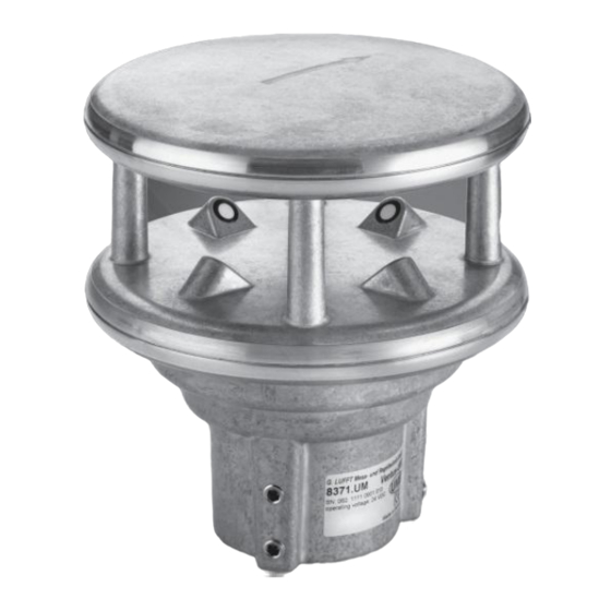
VENTUS-UMB
User manual
Lufft VENTUS-UMB User Manual
Ultrasonic wind sensors
Hide thumbs
1
2
Table Of Contents
3
4
5
6
7
8
9
10
11
12
13
14
15
16
17
18
19
20
21
22
23
24
25
26
27
28
29
30
31
32
33
34
35
36
37
38
39
40
41
42
43
44
45
46
47
48
49
50
51
52
53
54
55
56
57
58
59
60
61
62
63
64
65
66
67
68
69
70
71
72
73
74
75
76
page
of
76
Go
/
76
Contents
Table of Contents
Bookmarks
Table of Contents
Contents
Table of Contents
1 Please Read before Use
Symbols Used
Safety Instructions
Designated Use
Incorrect Use
Warranty
Brand Names
2 Scope of Supply
3 Order Number
4 Accessories
5 Additional Documents and Software
6 Equipment Description
Wind
Virtual Temperature
Air Pressure
Heating
7 Generation of Measurements
Current Measurement (Act)
Minimum and Maximum Values (Min and Max)
Average Value (Avg)
Vectorial Average Value (Vct)
8 Measurement Output
Virtual Air Temperature
Heating Temperature
Air Pressure
Wind Speed
Wind Direction
Wind Measurement Quality
Status Information
9 Installation
Fastening
North Alignment
Selecting the Installation Location
10 Connections
Supply Voltage
RS485 Interface
Analog Interface Circuits
Control Line
Connection to ISOCON-UMB (8160.UISO)
Use of Surge Protector (8379.USP-V)
SDI12 Connection
11 Commissioning
12 Configuration and Test
Lufft Configtool
Configuration
Value Retrieval
13 Firmware Update
14 Maintenance
15 Technical Data
Measuring Range / Accuracy
Drawing
16 EC Declaration of Conformity
17 Fault Description
18 Disposal
Within the EC
Outside the EC
19 Repair / Corrective Maintenance
Technical Support
20 Appendix
Channel List Summary
Channel List Summary Per TLS2002 FG3
Communication in Binary Protocol
Communication in ASCII Protocol
Communication in NMEA Protocol
Communication in SDI-12 Mode
Communication in Modbus Mode
21 List of Figures
22 Keyword Index
Advertisement
Quick Links
Download this manual
Table of
Contents
Previous
Page
Next
Page
1
2
3
4
5
Advertisement
Table of Contents
Need help?
Do you have a question about the VENTUS-UMB and is the answer not in the manual?
Ask a question
Questions and answers
Related Manuals for Lufft VENTUS-UMB
Accessories Lufft VS2k-UMB User Manual
Visibility sensor (18 pages)
Accessories Lufft VENTUS-USB Manual
Ultrasonic wind sensor (78 pages)
Accessories Lufft V200A-UMB User Manual
Ultrasonic wind sensors (76 pages)
Accessories Lufft ARS31Pro-UMB User Manual
Active road sensor (40 pages)
Accessories Lufft ARS31-UMB Operating Manual
Active road sensor (26 pages)
Accessories Lufft NIRS31-UMB Operating Manual
Non invasive road sensor (58 pages)
Accessories Lufft IRS31Pro-UMB User Manual
Intelligent road sensor (63 pages)
Accessories Lufft 8810.U051 Operating Manual
Active road sensor (34 pages)
Accessories Lufft WS800-UBM Manual
Smart weather sensors (146 pages)
Accessories Lufft MARWIS User Manual
(59 pages)
Accessories Lufft WS Series Quick Start
Smart weather sensor (2 pages)
Accessories Lufft SHM 31 User Manual
Snow depth sensor (73 pages)
Accessories Lufft WS10 User Manual
Smart weather sensor (40 pages)
Accessories Lufft CHM 15k Nimbus Manual
"nimbus" cloud height sensor (101 pages)
Accessories Lufft SHM31 Quick Start
Snow depth sensor (2 pages)
This manual is also suitable for:
Ventus-x-umb
V200a-umb
8371.umt
8371.umtx
8371.ua01
Table of Contents
Print
Rename the bookmark
Delete bookmark?
Delete from my manuals?
Login
Sign In
OR
Sign in with Facebook
Sign in with Google
Upload manual
Upload from disk
Upload from URL


Need help?
Do you have a question about the VENTUS-UMB and is the answer not in the manual?
Questions and answers