
Subscribe to Our Youtube Channel
Related Manuals for Stober PS6 Series


Summary of Contents for Stober PS6 Series
- Page 1 Multi-axis drive system with SI6 and PS6 Manual stober.com en-US 02/2019 ID 442728.05...
-
Page 2: Table Of Contents
Table of contents STOBER Table of contents Foreword .......................... 9 User information........................ 10 Storage and transfer .................... 10 Described product type.................... 10 Timeliness........................ 10 Original language...................... 10 Limitation of liability..................... 10 Formatting conventions .................... 11 2.6.1 Use of symbols ..................... 11 2.6.2... - Page 3 STOBER Table of contents Technical data........................ 38 General technical data.................... 38 Supply module ...................... 39 6.2.1 Electrical data .................... 39 6.2.2 Dimensions.................... 42 6.2.3 Weight ...................... 42 Drive controllers...................... 43 6.3.1 Electrical data .................... 43 6.3.2 Derating ...................... 51 6.3.3 Dimensions....................
- Page 4 Table of contents STOBER Example design for UL-compliant operation............... 80 7.4.1 Maximum operation on PS6A24.............. 81 7.4.2 Maximum operation on PS6A34.............. 82 7.4.3 Sample calculation .................. 83 Order overview of the hardware components............. 83 Storage .......................... 85 Supply module ...................... 85 Drive controller......................
- Page 5 11.1.3 Creating other modules and drive controllers.......... 161 11.1.4 Specifying a module ................... 161 11.1.5 Specifying the project ................. 162 11.2 Mechanical drive model .................... 162 11.2.1 Parameterizing the STOBER motor ............ 162 11.2.2 Parameterizing the axis model .............. 163 11.3 Testing the project configuration................ 165...
- Page 6 Table of contents STOBER 12 Communication ....................... 167 12.1 System requirements.................... 167 12.1.1 Personal firewall .................. 167 12.1.2 Protocols and ports for communication using routers ........ 168 12.2 Direct connection ...................... 168 12.3 Fieldbus ........................ 168 13 Diagnostics ........................ 169 13.1 Supply module ...................... 169 13.2 Drive controller......................
- Page 7 14.4 Replacing or updating the firmware ................ 228 14.5 Changing the fieldbus .................... 228 15 Service.......................... 229 15.1 STOBER electronics service .................. 229 15.2 Reverse documentation.................... 229 15.2.1 Creating reverse documentation in a new project ........ 229 15.2.2 Loading reverse documentation in an existing project ....... 230 16 Appendix ..........................
- Page 8 Table of contents STOBER 16.2 Wiring examples ....................... 239 16.2.1 Operation with 1 supply module .............. 239 16.2.2 Parallel connection .................. 240 16.2.3 UL-compliant connection of the supply module.......... 241 16.3 Device addressing .................... 242 16.4 DriveControlSuite...................... 243 16.4.1 System requirements.................. 243 16.4.2 Installation types..................
-
Page 9: Foreword
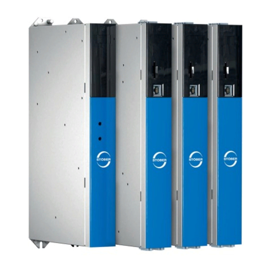
1 | Foreword Foreword The completely re-designed STOBER multi-axis drive system consists of the SI6 drive controller and PS6 supply module combination. Matching Quick DC-Link modules handle the energy supply for the networked drive controllers. The SI6 drive controller is available in four sizes as a single or double-axis controller with a nominal output current of up to 50 A. -
Page 10: User Information
Combinations with other 6th generation STOBER drive controllers are possible under certain general conditions. Information To ensure proper functionality, we recommend using cables from STOBER that are matched to the complete system. In case of use of unsuitable connection cables, we reserve the right to reject claims under the warranty. -
Page 11: Formatting Conventions
STOBER 2 | User information Formatting conventions Orientation guides in the form of signal words, symbols and special text markups are used to emphasize specific information so that you are able identify it in this documentation quickly. 2.6.1 Use of symbols Safety instructions are identified with the following symbols. -
Page 12: Markup Of Text Elements
2 | User information STOBER 2.6.2 Markup of text elements Certain elements of the body text are distinguished as follows. Quick DC-Link module Words or expressions with a special meaning Interpolated position mode Optional: File or product name or other name... -
Page 13: Conventions For Cables
STOBER 2 | User information 2.6.3 Conventions for cables In the cable connection descriptions, core colors are shortened and used as follows. Cable colors BLACK PINK BROWN BLUE VIOLET GREEN WHITE GRAY YELLOW ORANGE Formatting conventions Two-colored core: WHYE WHITEYELLOW (white and yellow) -
Page 14: Trademarks
2 | User information STOBER Trademarks The following names used in connection with the device, its optional equipment and its accessories are trademarks or registered trademarks of other companies: ® ® ® CANopen CANopen and CiA are registered European Union trademarks of CAN ®... -
Page 15: General Safety Instructions
The SI6 drive controller intended solely for the operation of STOBER LM series Lean motors, synchronous servo motors (e.g. from the STOBER EZ series), asynchronous motors or torque motors. -
Page 16: Transport And Storage
3 | General safety instructions STOBER The connection of other electronic loads or operation outside applicable technical specifications constitutes improper use. When installing drive controllers in machines, commissioning (i.e. commencing intended operation) may not be performed until it has been determined that the machine is in compliance with provisions from the following EC and EU directives: §... -
Page 17: Working On The Machine
Use in potentially explosive atmospheres § Use in environments with harmful substances as specified by EN 60721, such as oils, acids, gases, vapors, dust and radiation Implementation of the following applications is permitted only after approval from STOBER: § Use in non-stationary applications §... -
Page 18: Disposal
3 | General safety instructions STOBER Disposal Observe the current national and regional regulations when disposing of the product! Dispose of the individual product parts depending on their properties, e.g. as: § Electronic waste (circuit boards) § Plastic § Sheet metal §... -
Page 19: Ul-Compliant Use
STOBER 4 | UL-compliant use UL-compliant use This chapter contains relevant information for use under UL conditions (UL – Underwriters Laboratories). Surrounding air temperature and pollution degree The maximum surrounding air temperature for UL-compliant operation is 45 °C. Use in an environment with pollution degree 2 is permitted. - Page 20 4 | UL-compliant use STOBER The connection for the protective grounding on the housing is identified by the following grounding symbol Observe the notes in the chapter UL-compliant housing grounding [} 108] for correct installation. 2. Functional grounding In addition to the protective grounding, a functional grounding is required for proper operation of the PS6 drive system in combination with SI6 and of the motor.
- Page 21 Only the risks of electric shock and the risk of fire have been examined during UL acceptance at STOBER. Functional safety aspects have not been assessed during the UL approval process. These are assessed for STOBER by bodies such as the TÜV SÜD certification service.
-
Page 22: System Configuration
5 | System configuration STOBER System configuration The multi-axis drive system consists of at least one PS6 supply module and one SI6 drive controller. For the energy supply of the existing drive controllers in the group, you need suitable Quick DC-Link modules for the DC link connection for each supply module and for each drive controller. -
Page 23: Hardware Components
STOBER 5 | System configuration Hardware components Below you will find an overview of the available hardware components. 5.1.1 Supply module The PS6 supply module is available in two sizes. The type specifications used in this documentation refer to the nameplate that is placed on the side of the supply module. -
Page 24: Tab. 2 Meaning Of The Specifications On The Ps6 Nameplate
5 | System configuration STOBER Designation Value in example Meaning Types PS6A24 Device type according to type designation ID No. 56650 Identification number 003 SAT Production information Date 1602 Production week in format YYWW, in the example shown here year 2016, week 2... -
Page 25: Tab. 3 Example Code For The Ps6 Type Designation
STOBER 5 | System configuration 5.1.1.3 Type designation Tab. 3: Example code for the PS6 type designation Code Designation Design Series PowerSupply Generation Generation 6 Version 2 – 3 Size Power output stage Tab. 4: Meaning of the PS6 example code 5.1.1.4... - Page 26 5 | System configuration STOBER Terminal set for supply module The following designs are available: ID No. 138660 Terminal set for PS6A24. ID No. 138661 Terminal set for PS6A34.
-
Page 27: Drive Controller
STOBER 5 | System configuration 5.1.2 Drive controller The SI6 drive controller is available in several sizes as a single or double-axis controller. In addition, different safety options are available. The type specifications used in this documentation refer to the nameplate that is placed on the side of the drive controller. -
Page 28: Fig. 4 Sticker With Mv And Serial Number
5 | System configuration STOBER Designation Value in example Meaning Types SI6A061 Device type according to type designation ID No. 56645 Identification number of the basic device 012 SAT Production information Date 1712 Production week in format YYWW, in the example... -
Page 29: Tab. 8 Example Code For The Si6 Type Designation
STOBER 5 | System configuration 5.1.2.3 Type designation Tab. 8: Example code for the SI6 type designation Code Designation Design Series ServoInverter Generation Generation 6 Version 0 – 3 Size Power output stage Power output stage within the size Axis controller Single-axis controller... - Page 30 5 | System configuration STOBER SI6 in sizes 0 to 3 Note that the basic device is delivered without terminals. Suitable terminal sets are available separately for each size. Terminal set for drive controller The following designs are available: ID No. 138655 Terminal set for SI6A061Z/Y.
-
Page 31: Dc Link Connection
STOBER 5 | System configuration 5.1.3 DC link connection For the energy supply of the existing networked drive controllers, you need suitable Quick DC- Link modules of type DL6B for each PS6 supply module and each SI6 drive controller. For the horizontal connection, you receive DL6B rear section modules in various designs, matched to the size of the drive controller or supply module. -
Page 32: Controller
5.1.4 Controller The development of the MC6 motion controller and its integration into the STOBER product portfolio opens up new solutions for drive technology, especially for complex functions with demanding requirements for timing and precision. The SI6 drive controller is connected to the MC6 using EtherCAT. -
Page 33: Operating Motors, Encoders And Brakes
5 | System configuration 5.1.5 Operating motors, encoders and brakes You can use the SI6 drive controller to operate Lean motors of the STOBER LM series, synchronous servo motors (such as those of the STOBER EZ series), asynchronous motors or torque motors. -
Page 34: Accessories
5 | System configuration STOBER 5.1.6 Accessories You can find information about the available accessories in the following chapters. 5.1.6.1 Safety technology The safety modules are used to realize the STO safety function. They prevent the generation of a rotating magnetic field in the power unit of the drive controller. For an external requirement or in the event of error, the safety module switches the drive controller to the STO state. - Page 35 More detailed information can be found in the chapter Braking resistor [} 65]. 5.1.6.4 Choke STOBER offers different chokes corresponding to your application. More detailed information can be found in the chapter Choke [} 71].
- Page 36 5 | System configuration STOBER 5.1.6.5 Battery module Absolute Encoder Support (AES) ID No. 55452 Battery module for buffering the power supply when using the EnDat 2.2 digital inductive encoder with battery-buffered multi-turn stage, for example EBI1135 or EBI135. A battery is included.
-
Page 37: Software Components
MC6. In addition, the drive controllers can also independently handle motion tasks, such as referencing and jogging during commissioning. STOBER Drive Based STOBER Drive Based Synchronous applications and the drive- based operating modes (pp, pv, pt) of the... -
Page 38: Technical Data
6 | Technical data STOBER Technical data Technical data for the drive controllers, supply modules and accessories can be found in the following chapters. General technical data The following specifications apply equally to the SI6 drive controller and the PS6 supply module. -
Page 39: Supply Module
STOBER 6 | Technical data Supply module The following section contains specifications for the electrical data, dimensions and weight of the PS6 supply module. 6.2.1 Electrical data The electrical data of the available PS6 sizes as well as the properties of the brake chopper can be found in the following chapters. -
Page 40: Tab. 16: Ps6 Electrical Data, Size 2
6 | Technical data STOBER 6.2.1.2 Power unit: Size 2 Electrical data PS6A24 3 × 400 V , +32%/−50%, 50/60 Hz; 3 × 480 V , +10%/−58%, 50/60 Hz √2 × U 10 kW N,PU 25 A 1N,PU × 180% for 5 s; 1maxPU 1N,PU × 150% for 30 s 1N,PU 5000 µF... -
Page 41: Tab. 19 Brake Chopper Electrical Data
STOBER 6 | Technical data 6.2.1.5 Brake chopper Electrical data All types 780 – 800 V onCH 740 – 760 V offCH 22 Ω 2minRB 29.1 kW maxRB 13.2 kW effRB Tab. 19: Brake chopper electrical data Information Use braking resistors with thermal monitoring (see the chapter Braking resistor [} 65]). -
Page 42: Dimensions
6 | Technical data STOBER 6.2.2 Dimensions Fig. 5: PS6 dimensional drawing Dimension Size 2 Size 3 Supply module Width Depth Body height Fastening clip height Height incl. fastening clips Fastening holes (M5) Vertical distance 360+2 Vertical distance to the upper edge Tab. -
Page 43: Drive Controllers
STOBER 6 | Technical data Drive controllers The following chapters contain specifications for the electrical data, dimensions and weight of the drive controller. 6.3.1 Electrical data The electrical data of the available SI6 sizes can be found in the following sections. -
Page 44: Tab. 27 Si6 Electrical Data, Size 1
6 | Technical data STOBER 6.3.1.3 Power unit: Size 1 Electrical data SI6A161 SI6A162 280 – 800 V 0 – 700 Hz 0 – max. 470 µF 940 µF Tab. 27: SI6 electrical data, size 1 Nominal currents up to +45 °C (in the control cabinet) Electrical data SI6A161 SI6A162 4 kHz PWM,PU 12 A... -
Page 45: Tab. 30 Si6 Electrical Data, Size 2
STOBER 6 | Technical data 6.3.1.4 Power unit: Size 2 Electrical data SI6A261 SI6A262 280 – 800 V 0 – 700 Hz 0 – max. 940 µF 2250 µF Tab. 30: SI6 electrical data, size 2 Nominal currents up to +45 °C (in the control cabinet) Electrical data SI6A261 SI6A262 4 kHz PWM,PU 22 A... -
Page 46: Tab. 33 Si6 Electrical Data, Size 3
6 | Technical data STOBER 6.3.1.5 Power unit: Size 3 Electrical data SI6A361 280 – 800 V 0 – 700 Hz 0 – max. 2250 µF Tab. 33: SI6 electrical data, size 3 Nominal currents up to +45 °C (in the control cabinet) Electrical data SI6A361 4 kHz PWM,PU 50 A 2N,PU 210% for 2 s... -
Page 47: Tab. 36 X101 Electrical Data
STOBER 6 | Technical data 6.3.1.6 Binary inputs X101 specification for binary signals Electrical data Binary input Value Low level BE1 – BE4 0 – 8 V High level 12 – 30 V 30 V 1max 16 mA 1max BE1 – BE2 10 kHz 1max BE3 –... -
Page 48: Fig. 6 Asymmetric Load On Double-Axis Controllers
6 | Technical data STOBER 6.3.1.7 Asymmetric load on double-axis controllers Operating two motors on one double-axis controller makes it possible to operate one of the motors with a continuous current above the nominal drive controller current if the continuous current of the second connected motor is lower than the nominal drive controller current. -
Page 49: Tab. 38 Power Loss Data In Accordance With En 50598 For One Axis Of A Si6 Drive Controller
STOBER 6 | Technical data 6.3.1.8 Power loss data in accordance with EN 50598 Type Nominal Apparent Absolute Operating points Comparison current power losses class 2N,PU V,CU (0/25) (0/50) (0/100) (50/25) (50/50) (50/100) (90/50) (90/100) Relative losses [kVA] SI6A06x Max. 10 0.71... - Page 50 6 | Technical data STOBER General conditions The specified losses apply to an axis of a drive controller and take into account the proportionate losses of the PS6 supply module for that axis. For a group with a total of x axes, the values are to be multiplied by the number of axis controllers (x), e.g. x = 4 for 1 × PS6 and 2 × SI6A062.
-
Page 51: Derating
STOBER 6 | Technical data 6.3.1.9 Power loss data of accessories If you intend to order the drive controller with accessory parts, losses increase as follows. Type Absolute losses SR6 safety module SY6 safety module Tab. 39: Absolute losses in the accessories Information Note the absolute power loss of the encoder (usually <... - Page 52 6 | Technical data STOBER 6.3.2.2 Effect of the surrounding temperature Derating as a function of the surrounding temperature is determined as follows: § 0 °C to 45 °C: No restrictions (D = 100%) § 45 °C to 55 °C: Derating −2.5%/K Example The drive controller needs to be operated at 50 °C.
-
Page 53: Dimensions
STOBER 6 | Technical data 6.3.3 Dimensions 0 – 2 Fig. 7: SI6 dimensional drawing Dimension Size 0 Size 1 Size 2 Size 2 Size 3 Drive controller Width Depth Body height Fastening clip height Height incl. fastening clips Total height incl. -
Page 54: Weight
6 | Technical data STOBER 6.3.4 Weight Type Weight without packaging [g] Weight with packaging [g] SI6A061 2980 4600 SI6A062 3460 5060 SI6A161 3880 5260 SI6A162 4820 6240 SI6A261 4760 6180 SI6A262 6240 7420 SI6A361 6180 7360 Tab. 42: SI6 weight [g]... -
Page 55: Dl6B Assignment - Si6 And Ps6
STOBER 6 | Technical data 6.4.2 DL6B assignment – SI6 and PS6 DL6B is available in the following designs suitable for the individual drive controller types and supply module types: Type DL6B10 DL6B11 DL6B12 DL6B20 DL6B21 ID No. 56655 56656... -
Page 56: Weight
6 | Technical data STOBER Dimension DL6B10 DL6B11 DL6B12 DL6B20 DL6B21 Quick DC-Link Width Depth Depth incl. attachment bolts Height Fastening clip height Height incl. fastening clips Fastening holes Vertical distance 393+2 (wall mounting) Vertical distance (module mounting) Vertical distance to the... -
Page 57: Safety Technology
STOBER 6 | Technical data Safety technology The SR6 option adds the STO safety function to the SI6 drive controller through terminal X12. Information If you would like to use STO safety function over terminals, be sure to read the SR6 manual;... -
Page 58: Operating Motors
6 | Technical data STOBER Operating motors You can operate the following motors with the specified control modes on the drive controller. Motor type B20 Control mode Encoders Other settings Characteristics LM Lean 32: LM - sensorless No encoder Without field... -
Page 59: Evaluable Encoders
STOBER 6 | Technical data Evaluable encoders The technical data of the evaluable encoder can be found in the following chapters. You can use all of the encoder connections as position encoders. Master encoders may be connected only to connection X4A or X101. The use as a motor encoder depends on which encoder design is required by your motor and supported by the encoder connection. -
Page 60: Tab. 52 Endat 2.1 Digital Specification
6 | Technical data STOBER 6.7.3 EnDat 2.1 digital encoders Specification EnDat 2.1 digital 12 V (unregulated) 250 mA 2max — 2min Encoder design Single-turn and multi-turn; not suitable for linear encoders Clock frequency 2 MHz Max. cable length 100 m, shielded Tab. 52: EnDat 2.1 digital specification EnDat 2.2 digital encoders... -
Page 61: Tab. 54 Ssi Specification
STOBER 6 | Technical data SSI encoders Specification SSI signals 12 V (unregulated) 250 mA 2max Encoder design Single-turn and multi-turn Clock frequency 250 kHz and 600 kHz Sampling rate 250 µs Monoflop time ≤ 30 µs Code Binary or gray Format 13, 24 or 25 bits... -
Page 62: Tab. 56 Specification For Resolver Signals
Encoder design Single-turn and multi-turn Max. cable length 100 m, shielded Tab. 57: Specification for HIPERFACE DSL Unsuitable encoder models The following STOBER encoder models may be connected: Encoder model Code according to type designation ECI 1118 EQI 1130 ECI 1319... -
Page 63: X101 For Encoders
STOBER 6 | Technical data 6.7.4 X101 for encoders Electrical data Binary input Incremental signals, pulse train signals Low level BE1 – BE4 0 – 8 V High level 15 – 30 V 30 V 1max 16 mA 1max BE1 – BE2 10 kHz 1max BE3 –... -
Page 64: Controllable Brakes
6 | Technical data STOBER Controllable brakes The brake of axis A is connected to X2A. Connect the brake of axis B to X2B for double-axis controllers. You can control the following brakes: § Directly connected 24 V brakes § Indirectly connected brakes (e.g. over coupling contactor) The brake is supplied over X300. -
Page 65: Braking Resistor
6 | Technical data Braking resistor In addition to the supply modules, STOBER offers braking resistors in the various sizes and performance classes described below. For the selection, note the minimum permitted braking resistors specified in the technical data of the supply modules. In the event of a fault, such as a defective brake chopper, the supply module must be disconnected from the power supply. -
Page 66: Fig. 9 Kwadqu 420×91 Dimensional Drawing
6 | Technical data STOBER Information The temperature switch reports a resistor overload. The evaluation in the form of a warning or line-side shutdown of the power supply must take place separately, e.g. using the PS6 supply module. Observe the wiring example for the supply module in the chapter UL-compliant connection of the supply module [} 241]... -
Page 67: Fzzmqu Tubular Fixed Resistor
STOBER 6 | Technical data 6.9.3 FZZMQU tubular fixed resistor Properties Specification FZZMQU 400×65 ID No. 56635 Type Tubular fixed resistor with temperature switch Resistance [Ω] Power [W] 1200 Thermal time constant τ Pulse power for < 1 s [kW] Weight [kg] Approx. -
Page 68: Fig. 10 Fzzmqu 400×65 Dimensional Drawing
6 | Technical data STOBER Dimensions Dimension FZZMQU 400×65 L × D 400 × 65 6.5 × 12 Tab. 67: FZZMQU 400×65 dimensions [mm] Fig. 10: FZZMQU 400×65 dimensional drawing... -
Page 69: Fgfkqu Steel-Grid Fixed Resistor
STOBER 6 | Technical data 6.9.4 FGFKQU steel-grid fixed resistor Properties Specification FGFKQU 31005 ID No. 56636 Type Steel-grid fixed resistor with temperature switch Resistance [Ω] Power [W] 2500 Thermal time constant τ Pulse power for < 1 s [kW] Weight [kg] Approx. -
Page 70: Fig. 11 Fgfkqu 31005 Dimensional Drawing
6 | Technical data STOBER Dimensions Dimension FGFKQU 31005 Tab. 70: FGFKQU 31005 dimensions [mm] ø10,5 Fig. 11: FGFKQU 31005 dimensional drawing... -
Page 71: Choke
STOBER 6 | Technical data 6.10 Choke Technical specifications for suitable chokes can be found in the following chapters. 6.10.1 TEP output choke Output chokes are required for drive controllers of sizes 0 to 2 and for a cable length of 50 m or longer in order to reduce interference pulses and protect the drive system. -
Page 72: Fig. 12 Derating The Nominal Current Depending On The Clock Frequency
6 | Technical data STOBER Derating – Effect of the clock frequency I [A] f [Hz] Fig. 12: Derating the nominal current depending on the clock frequency, TEP3720-0ES41 4 kHz clock frequency 8 kHz clock frequency I [A] f [Hz] Fig. 13: Derating the nominal current depending on the clock frequency, TEP3820-0CS41 4 kHz clock frequency... -
Page 73: Fig. 14 Derating The Nominal Current Depending On The Clock Frequency
STOBER 6 | Technical data I [A] f [Hz] Fig. 14: Derating the nominal current depending on the clock frequency, TEP4020-0RS41 4 kHz clock frequency 8 kHz clock frequency Derating – Effect of surrounding temperature 72 % 72 % Surrounding temperature [°C] Fig. 15: Derating the nominal current based on surrounding temperature... -
Page 74: Fig. 16 Derating The Nominal Current Depending On Installation Elevation
6 | Technical data STOBER Derating – Effect of the installation elevation 87 % 1000 2000 3000 4000 5000 Installation altitude [m] Fig. 16: Derating the nominal current depending on installation elevation 67 % 1000 2000 3000 4000 5000 Installation altitude [m]... -
Page 75: Fig. 18 Tep Dimensional Drawing
STOBER 6 | Technical data Dimensions and weight Dimension TEP3720-0ES41 TEP3820-0CS41 TEP4020-0RS41 Height h [mm] Max. 153 Max. 153 Max. 180 Width w [mm] Depth d [mm] Vertical distance – Fastening holes a1 [mm] Vertical distance – Fastening holes a2 [mm] Horizontal distance –... -
Page 76: Project Configuration
7 | Project configuration STOBER Project configuration Relevant information on the project configuration and design of your drive system can be found in the following chapters. Supply module 7.1.1 Information on design and operation Information Note for the design of the supply module that the summed self-capacitance of all SI6 drive controllers may not exceed the maximum charging capacity of the supply module. -
Page 77: Parallel Connection Of Supply Modules
§ There are no restrictions for the position of a supply module within the group. § Mixed supply operation with drive controllers of the 6th STOBER drive controller generation is not permitted. Parallel connection The following table shows example combinations for parallel connection. A derating factor of 0.8 is taken into account for the values. -
Page 78: Dc Link Connection
7 | Project configuration STOBER DC link connection Braked motors work like generators: Operating with an active drive controller, they convert kinetic energy from movement into electrical energy. This electrical energy is stored in the DC link capacitors of the drive controller. It is supplied to powered motors with connected DC links and thus used efficiently. -
Page 79: Mixed Operation
Mixed operation You can combine the PS6 supply module and SI6 drive controller with other drive controllers from the 6th generation of STOBER drive controllers. For UL-compliant operation, note that mixed operation is not currently possible. In mixed operation, only device types of the same series and size may be supplied with power. -
Page 80: Example Design For Ul-Compliant Operation
7 | Project configuration STOBER Example design for UL-compliant operation The information and examples in this chapter are based on an input voltage of 480 V . For a more detailed design, SERVOsoft is helpful mechanical and electrical sizing software for drive systems. -
Page 81: Maximum Operation On Ps6A24
STOBER 7 | Project configuration 7.4.1 Maximum operation on PS6A24 Drive controller Quick DC-Link Limiting factor Examples Type Self- Nominal input Width Type Charging Nominal Length of the Partial load of Partial load of capacitance current (DC) [mm] capacity output current... -
Page 82: Maximum Operation On Ps6A34
7 | Project configuration STOBER 7.4.2 Maximum operation on PS6A34 Drive controller Quick DC-Link Limiting factor Examples Type Self- Nominal input Width Type Charging Nominal Length of the Partial load of Partial load of capacitance current (DC) [mm] capacity output current... -
Page 83: Sample Calculation
STOBER 7 | Project configuration 7.4.3 Sample calculation Assume 20 motors, each with a nominal current of 2 A and an operating time of 100% (full load). The design calls for 10 SI6A062 double-axis controllers with a nominal output current of 2 ×... - Page 84 Copper rails Each device group requires 3 copper rails (DC+, DC−, grounding). The copper rails (EATON CU12X5 034121) with a standard length of 1500 mm must be ordered from STOBER under the ID No. 56676. The required length of the copper rails corresponds to the total length of the group minus 5 mm: §...
-
Page 85: Storage
STOBER 8 | Storage Storage Store the products in a dry and dust-free room if you do not install them immediately. Observe the Transport and storage conditions [} 38] specified in the technical data. Supply module No reforming is required for the PS6 supply module even after long storage times. -
Page 86: Annual Reforming
8 | Storage STOBER 8.2.1 Annual reforming To prevent damage to stored drive controllers, STOBER recommends connecting stored devices to the supply voltage once per year for one hour. The following graphic shows the predominant supply connection. L1 L2 D- D+ D- D+ Fig. 20: Annual reforming... -
Page 87: Reforming Before Commissioning
STOBER 8 | Storage 8.2.2 Reforming before commissioning If reforming is not possible every year, institute reforming on stored devices before commissioning. Note that the voltage levels depend on the storage time. The following graphic shows the predominant supply connection. -
Page 88: Fig. 22 Voltage Levels Dependent On Storage Time
8 | Storage STOBER t [h] Fig. 22: Voltage levels dependent on storage time Storage time of 1 – 2 years: Apply voltage for 1 hour before switching on. Storage time of 2 – 3 years: Implement reforming according to the graph before switching Storage time ≥ 3 years: Implement reforming according to the graph before switching Storage time < 1 year:... -
Page 89: Installation
STOBER 9 | Installation Installation The following chapter describes the installation of the Quick DC-Link rear modules for the DC link connection as well as the subsequent installation of the drive controllers and supply modules. Safety instructions for installation Installation work is permitted only when no voltage is present. Observe the 5 safety rules; see... -
Page 90: Choke
9 | Installation STOBER 9.2.2 Choke In relation to the flow of cooling air, the following mounting positions are permitted for the TEP output choke: 9.2.3 Braking resistor Note the permitted mounting positions for the braking resistor. KWADQU flat resistor Permitted installation: §... - Page 91 STOBER 9 | Installation FGFKQU steel-grid fixed resistor Permitted installation: § On vertical surfaces with terminals downwards § Top and bottom perforated sheets § On horizontal surfaces § Installation on, next to or in the control cabinet possible Impermissible installation: §...
-
Page 92: Minimum Clearances
9 | Installation STOBER Minimum clearances Note the minimum clearances for installation below. Drive controllers and supply modules Fig. 24: Minimum clearances The specified dimensions refer to the outside edges of the drive controller or supply module including the Quick DC-Link rear section module. -
Page 93: Drilling Diagrams And Dimensions
STOBER 9 | Installation Drilling diagrams and dimensions You can find drilling diagrams and dimensions for a multi-axis drive system with SI6 and PS6 and for accessories in the following chapters. 9.4.1 Multi-axis drive system 1 – 2 Fig. 25: Drilling diagram for multi-axis drive system... -
Page 94: Length Of Copper Rails
9 | Installation STOBER Length of copper rails For the installation of the Quick DC-Link modules, you require three prepared copper rails with a cross-section of 5 × 12 mm. The length of the copper rails is 5 mm shorter than the total width of the group, i.e. the total width of all DL6B Quick DC-Link modules present in the group: B = A −... -
Page 95: Installing The Dc Link Connection
STOBER 9 | Installation Installing the DC link connection Observe the installation notes when installing the DC link connection and associated hardware components. 9.6.1 Order overview of the components for the DC link connection Device Terminal set Quick DC-Link Type ID No. - Page 96 9 | Installation STOBER Perform the following steps in the specified order. ü You have tapped holes for fastening screws on the mounting plate at the installation location in accordance with the drilling diagram and taking into consideration the different device dimensions.
- Page 97 STOBER 9 | Installation 2. Insert the insulation connection pieces between the modules and insulation end section each at the left edge of the first module and at the right edge of the last module. Ensure correct alignment of the end section using the marking on the outside and the insertion aids for the copper rails on the inside.
- Page 98 9 | Installation STOBER 6. Fasten each of the copper rails with two quick fastening clamps per rail and Quick DC-Link module. Make certain the contact points of the copper rails do not become contaminated. ð You have installed the Quick DC-Link. In the next step, build over the Quick DC-Link...
-
Page 99: Installing Drive Controllers And Supply Modules
STOBER 9 | Installation Installing drive controllers and supply modules DANGER! Electrical voltage! Risk of fatal injury due to electric shock! ▪ Always switch off all power supply voltage before working on the devices! ▪ Note the discharge time of the DC link capacitors. You can only determine the absence of voltage after this time period. - Page 100 9 | Installation STOBER 1. Remove terminal X22 from the appropriate terminal set. Connect the brown cable D+ of the bottom of the Quick DC-Link module to D+ of terminal X22, and the black cable D- of the Quick DC-Link module to D- of terminal X22. Note that the terminal is only connected at a later point in time.
- Page 101 STOBER 9 | Installation 3. Fasten the drive controller or the supply module with the nut and washer assemblies (M5, 3.5 Nm) to both threaded bolts of the Quick DC-Link module. The nut and washer assemblies are included with the Quick DC-Link module.
-
Page 102: Connection
10 | Connection STOBER Connection The following chapters describe the connection of the supply modules and drive controllers as well as the available accessories. 10.1 Safety instructions for connection Connection work is permitted only when no voltage is present. Observe the 5 safety rules; see... -
Page 103: Line Routing
STOBER 10 | Connection The protection class of the devices is protective grounding. This means operation is permitted only if the protective grounding conductor is connected according to requirements. All protective ground connections are identified by "PE" or the international symbol for grounding (IEC 60417, symbol 5019). -
Page 104: Ce-Compliant Line Fuse
10 | Connection STOBER 10.3.2 CE-compliant line fuse Every supply module in the group supplied with power must be protected against overload and short circuit at the grid input. To do this, a safety combination consisting of overload protection and semiconductor short-circuit protection is connected in series. A miniature circuit breaker protects against overload and a safety fuse against short circuit. -
Page 105: Ul-Compliant Line Fuse
10.3.5 Residual current protective device STOBER devices can be protected with a residual current protective device (RCD) to detect residual currents. Residual current protective devices prevent electrical accidents, especially ground fault through the body. They are generally classified by their triggering limit and suitability for detecting different types of residual currents. - Page 106 10 | Connection STOBER DANGER! Electrical voltage! Risk of fatal injury due to electric shock! Leakage currents with a DC current component may occur in 3-phase installations. ▪ Always protect 3-phase installations with type B residual current protective devices, sensitive to all currents.
-
Page 107: Ce-Compliant Housing Grounding
STOBER 10 | Connection 10.3.6 CE-compliant housing grounding Connect the grounding conductor to the supply module over terminal X10. Additional requirements for protective equipotential bonding apply in the event of ground leakage currents > 10 mA. At least one of the following conditions must be fulfilled: §... -
Page 108: Ul-Compliant Housing Grounding
10 | Connection STOBER 10.3.7 UL-compliant housing grounding Note that UL-compliant operation requires just a single grounding conductor. The chassis of the PS6A/SI6A units is to be bonded through the M6 grounding studs on the PS6A units (4.0 Nm, 35 Lb.inch). The chassis of the SI6A units are to be bonded by means of proper mounting of the SI6A unit(s) by means of two mounting screws on top of the DL6B unit(s). -
Page 109: Emc Recommendations
STOBER 10 | Connection 10.3.8 EMC recommendations Information This chapter provides general information on EMC-compliant installation. These are recommendations. Depending on the application, the ambient conditions as well as the legal requirements, measures beyond these recommendations may be required. Lay the power line, motor cable and signal lines separately from each other, e.g. in separate conduits. -
Page 110: Supply Module
10 | Connection STOBER 10.4 Supply module For detailed information about the terminals and correct connection of the supply module, refer to the following chapters. Information For UL-compliant operation: The connections marked with PE are intended solely for the functional grounding. -
Page 111: X10: 400 V Supply
STOBER 10 | Connection 10.4.2 X10: 400 V supply Terminal X10 is used to connect the supply module to the supply grid. Conductor cross-sections for the power connection When selecting the conductor cross-section, note the line fuse, the maximum permitted conductor cross-section of terminal X10, the routing method and the surrounding temperature. -
Page 112: X11: 24 V Supply
10 | Connection STOBER 10.4.3 X11: 24 V supply The connection of 24 V to X11 is required for the power supply of the control unit. ATTENTION! Device damage due to overload! If the 24 V power supply is looped to multiple devices over the terminal, the terminal may be damaged by a current that is too high. -
Page 113: X21: Braking Resistor
STOBER 10 | Connection 10.4.4 X21: Braking resistor Terminal X21 is available for the connection of a braking resistor. Terminal Designation Function Braking resistor connection 1 | 2 Tab. 90: X21 connection description For connecting wiring, observe the terminal specifications in the chapter ISPC 5 -STGCL-7,62 [} 236]. -
Page 114: X23: Temperature Monitoring Of Braking Resistor
10 | Connection STOBER Wiring example The examples in the chapter Wiring examples [} 239] illustrate the basic connection based on a DC link connection with DL6B Quick DC-Link. 10.4.6 X23: Temperature monitoring of braking resistor Connect the temperature monitoring of the braking resistor to terminal X23. UL-compliant... -
Page 115: Connecting The Supply Module
STOBER 10 | Connection For connecting wiring, observe the terminal specifications in the chapter FMC 1,5 -ST-3,5 [} 232]. Cable requirements Feature All sizes Max. cable length 30 m Tab. 95: Cable length [m] 10.4.8 Connecting the supply module DANGER! Electrical voltage! Risk of fatal injury due to electric shock! ▪... -
Page 116: Drive Controller
10 | Connection STOBER 10.5 Drive controller The following section contains detailed information about the terminals and the correct connection of the drive controller. Information For UL-compliant operation: The connections marked with PE are intended solely for the functional grounding. -
Page 117: X2A: Brake A
STOBER 10 | Connection 10.5.2 X2A: Brake A The brake of axis A is connected to X2A. All device types of the SI6 drive controller can control a 24 V brake as standard. Information Note that brakes from other manufacturers may be connected only after consultation with STOBER. -
Page 118: X2A: Motor Temperature Sensor A
10 | Connection STOBER 10.5.3 X2A: Motor temperature sensor A The motor temperature sensor of axis A is connected to terminal X2A. All device types of the SI6 drive controller have connections for thermistors. You can connect a maximum of two PTC triplets to X2A. -
Page 119: X2B: Brake B
STOBER 10 | Connection Cable requirements Motor connection Size 0 to 2 Size 3 Without output choke 50 m, shielded 100 m, shielded With output choke 100 m, shielded — Tab. 101: Maximum cable length of the power cable [m] 10.5.4 X2B: Brake B The brake of axis B is connected to X2B for double-axis controllers. -
Page 120: Tab. 102 X4A Connection Description For Endat 2.2 Digital Encoders And Ssi Encoders
10 | Connection STOBER EnDat 2.2 digital encoders and SSI encoders Socket Designation Function 8|7|6|5|4|3|2|1 — — Reference potential for encoder supply to pin 15|14|13|12|11|10| — — Encoder supply Data+ Differential input for DATA — — — — Clock+ Differential input for CLOCK —... -
Page 121: Tab. 103 X4A Connection Description For Differential Ttl And Differential Htl (Htl Over Ht6 Adapter) Incremental Encoders
STOBER 10 | Connection Differential TTL and differential HTL incremental encoders (HTL over HT6 adapters) Socket Designation Function 8|7|6|5|4|3|2|1 — — Reference potential for encoder supply to pin 15|14|13|12|11|10| — — Encoder supply Differential input for B channel — —... -
Page 122: Tab. 104 X4A Connection Description For Resolvers
10 | Connection STOBER Resolver Socket Designation Function 8|7|6|5|4|3|2|1 S4 Sin+ Sin input R1 Ref− Reference potential for pin 6 S3 Cos+ Cos input 15|14|13|12|11|10| — — — — R2 Ref+ Resolver excitation signal 1TP1 Reserve — — S2 Sin−... -
Page 123: Tab. 106 Cable Length [M]
Tab. 106: Cable length [m] Information To ensure proper functionality, we recommend using cables from STOBER that are matched to the complete system. In case of use of unsuitable connection cables, we reserve the right to reject claims under the warranty. -
Page 124: X4B: Encoder B
Tab. 110: Cable length [m] Information To ensure proper functionality, we recommend using cables from STOBER that are matched to the complete system. In case of use of unsuitable connection cables, we reserve the right to reject claims under the warranty. -
Page 125: X11: 24 V Supply
STOBER 10 | Connection 10.5.9 X11: 24 V supply The connection of 24 V to X11 is required for the power supply of the control unit. ATTENTION! Device damage due to overload! If the 24 V power supply is looped to multiple devices over the terminal, the terminal may be damaged by a current that is too high. -
Page 126: X12: Safety Technology (Sr6 Option)
10 | Connection STOBER 10.5.10 X12: Safety technology (SR6 option) The SR6 option adds the STO safety function to the SI6 drive controller through terminal X12. Information If you would like to use STO safety function over terminals, be sure to read the SR6 manual;... -
Page 127: X20A: Motor A
STOBER 10 | Connection 10.5.11 X20A: Motor A The motor of axis A is connected to X20A. UL-compliant operation The external motors which are connected to the inverter units SI6 units shall not be grounded over the modular drive system. The bonding/grounding of the motor(s) shall occur in the end use application in accordance with the requirements of applicable electrical codes/standards. -
Page 128: X20B: Motor B
Tab. 120: Maximum cable length of the power cable [m] Information To ensure proper functionality, we recommend using cables from STOBER that are matched to the complete system. In case of use of unsuitable connection cables, we reserve the right to reject claims under the warranty. -
Page 129: Tab. 122 X22 Connection Description, Sizes 1 And 2 (Single-Axis Controllers)
STOBER 10 | Connection Sizes 1 and 2 (single-axis controllers) Terminal Designation Function D− DC link connection 1 | 2 Tab. 122: X22 connection description, sizes 1 and 2 (single-axis controllers) For connecting wiring, observe the terminal specifications in the chapter ISPC 16 -ST-10,16 [} 237]. -
Page 130: 10.5.14 X101: Be1 - Be4
10 | Connection STOBER 10.5.14 X101: BE1 – BE4 The binary inputs 1 to 4 are available on terminal X101. X101 for binary signals For evaluating binary signals at X101, note the specification for the binary inputs in the technical... -
Page 131: 10.5.15 X103: Be6 - Be9
STOBER 10 | Connection Connecting wiring For connecting wiring, observe the terminal specifications in the chapter FMC 1,5 -ST-3,5 [} 232]. Cable requirements Feature All sizes Max. cable length 30 m Tab. 127: Cable length [m] 10.5.15 X103: BE6 – BE9 The binary inputs 6 to 9 are available on terminal X103. -
Page 132: Tab. 95 Cable Length [M]
10 | Connection STOBER Single-ended HTL pulse train Terminal Designation Function — — 5|4|3|2|1 Frequency Direction DGND Reference ground; not bridged with X101, pin Tab. 130: X103 connection description for single-ended HTL pulse/direction signals, axis B Connecting wiring For connecting wiring, observe the terminal specifications in the chapter FMC 1,5 -ST-3,5 [} 232]. -
Page 133: 10.5.16 X200, X201: Ethercat
Tab. 132: X200 and X201 connection description Cable requirements Information To ensure proper functionality, we recommend using cables from STOBER that are matched to the complete system. In case of use of unsuitable connection cables, we reserve the right to reject claims under the warranty. -
Page 134: 10.5.17 X200, X201: Profinet
10 | Connection STOBER 10.5.17 X200, X201: PROFINET In order to be able to connect the drive controllers to other PROFINET nodes, an integrated switch with both X200 and X201 RJ-45 sockets is provided. The sockets are located on top of the device. -
Page 135: 10.5.18 X300: Brake 24 V Supply
STOBER 10 | Connection 10.5.18 X300: Brake 24 V supply X300 is used to supply the brake. ATTENTION! Device damage due to overload! If the 24 V power supply is looped to multiple devices over the terminal, the terminal may be damaged by a current that is too high. -
Page 136: X700: Sd Slot
128 MB to 32 GB are supported. SDHC cards with a storage capacity of 64 GB can be used only if they have been first reformatted to max. 32 GB. Since higher capacities increase the controller starting time, STOBER recommends the use of cards with a storage capacity from 2 to 4 GB. -
Page 137: 10.5.20 Connecting A Drive Controller
STOBER 10 | Connection 10.5.20 Connecting a drive controller DANGER! Electrical voltage! Risk of fatal injury due to electric shock! ▪ Always switch off all power supply voltage before working on the devices! ▪ Note the discharge time of the DC link capacitors. You can only determine the absence of voltage after this time period. -
Page 138: Output Choke
10 | Connection STOBER Top of the device: ü You have a system circuit diagram describing the connection of the drive controller. 1. Connect the 24 V power supply for the control electronics to terminal X11 and attach the terminal. 2. If you use the STO safety function, connect it as follows: 2.1. -
Page 139: Fig. 31 Tep Output Choke Connection Example
STOBER 10 | Connection Fig. 31: TEP output choke connection example Shielded connection of the power cable Note the following points for the connection of the power cable for a motor with output choke: § Ground the shield of the power cable over large contact areas in the immediate vicinity of the output choke, for example with electrically conductive metal cable clips on a grounded connection rail. -
Page 140: Cables
When using a motor brake, pay attention to the voltage drop in the supply voltage on the line. Information To ensure proper functionality, we recommend using cables from STOBER that are matched to the complete system. In case of use of unsuitable connection cables, we reserve the right to reject claims under the warranty. -
Page 141: Power Cables
STOBER 10 | Connection 10.7.1 Power cables Synchronous servo motors and Lean motors from STOBER are equipped with plug connectors as standard. STOBER provides suitable cables in various lengths, conductor cross-sections and connector sizes. 10.7.1.1 Connection description Depending on the size of the motor plug connector, power cables are available in the following designs: §... - Page 142 10 | Connection STOBER Power cables – con.15 plug connector Motor Cable Drive controller (3) – (5) Motor Designation Int. motor Core No./ connection Core color Core color X300 diagram — — — — — — 1TP1 — — 1TP2 —...
- Page 143 STOBER 10 | Connection Power cables – con.23 plug connectors Motor Cable Drive controller (3) – (5) Motor Designation Int. motor Core No./ connection Core color Core color X300 diagram — — — — — — 1BD1 — — 1BD2 —...
- Page 144 10 | Connection STOBER Power cables – con.40 plug connectors Motor Cable Drive controller (3) – (5) Motor Designation Int. motor Core No./ connection Core color Core color X300 diagram — — — — — — 1BD1 — — −...
-
Page 145: Encoder Cables
10 | Connection 10.7.2 Encoder cables STOBER motors are equipped with encoder systems and plug connectors as standard. STOBER provides suitable cables in various lengths, conductor cross-sections and connector sizes. Depending on the respective motor types, different encoder systems can be used. - Page 146 10 | Connection STOBER Encoder cables – con.15 plug connector The power supply is buffered for EnDat 2.2 digital "EBI 1135" and "EBI 135" inductive encoders with a multi-turn function. In this case, pin 2 and pin 3 of the motor are assigned to the U 2BAT buffer battery.
- Page 147 STOBER 10 | Connection Encoder cables – con.17 plug connector The power supply is buffered for EnDat 2.2 digital "EBI 1135" and "EBI 135" inductive encoders with a multi-turn function. In this case, pin 2 and pin 3 of the motor are assigned to the U 2BAT buffer battery.
- Page 148 10 | Connection STOBER Encoder cables – con.23 plug connector Motor Cable Drive controller Connection Designation Core color Core color diagram Clock+ Sense U — — — — — — — — Data− Data+ — — — — Clock− —...
- Page 149 STOBER 10 | Connection 10.7.2.2 SSI encoders Suitable encoder cables are described below. 10.7.2.2.1 Connection description con.23 Plug connectors STOBER encoder cable D-sub X4 Encoder cables – con.23 plug connector Motor Cable Drive controller Connection Designation Core color Core color...
- Page 150 Suitable encoder cables are described below. 10.7.2.3.1 Connection description con.23 Plug connectors STOBER encoder cable D-sub X4 Information For the connection of an HTL incremental encoder to terminal X4 of the SC6 or SI6 drive controller, you need the HT6 adapter (ID No. 56665). HT6 takes over level conversion from HTL signals to TTL signals.
- Page 151 STOBER 10 | Connection Length x [mm] Diameter y [mm] Tab. 154: con.23 dimensions 10.7.2.4 Resolver Suitable encoder cables are described below. 10.7.2.4.1 Connection description con.15 con.17 con.23 Plug connector STOBER encoder cable D-sub X4...
- Page 152 10 | Connection STOBER Encoder cables – con.15 plug connector Motor Cable Drive controller Connection Designation Core color Core color diagram S3 Cos+ S1 Cos− S4 Sin+ S2 Sin− 1TP1 1TP2 R2 Ref+ YEWH/ BKWH R1 Ref− RDWH — —...
- Page 153 STOBER 10 | Connection Encoder cables – con.17 plug connector Motor Cable Drive controller Connection Designation Core color Core color diagram S3 Cos+ S1 Cos− S4 Sin+ S2 Sin− 1TP1 1TP2 R2 Ref+ YEWH/ BKWH R1 Ref− RDWH — —...
- Page 154 10 | Connection STOBER Encoder cables – con.23 plug connector Information For connecting STOBER resolver cables with a 9-pin D-sub connector, you also require the AP6A00 interface adapter (ID No. 56498, 9-pin to 15-pin D-sub), available separately. Motor Cable Drive...
-
Page 155: One Cable Solution
Information For connecting as a One Cable Solution, use exclusively hybrid cables from STOBER. The use of unsuitable cables or poorly made connections can cause subsequent damage. For this reason, we reserve the right to reject claims under the warranty in this case. - Page 156 10 | Connection STOBER con.15 1BD1 1BD2 con.23 DSL- DSL+ con.40 Plug connector STOBER hybrid cable Connection to terminal X20, motor Connection to terminal X2, brake supply D-sub X4...
- Page 157 STOBER 10 | Connection Hybrid cable – con.15 plug connector Motor Cable Drive controller (3) – (5) Connection Designa- Core color Core No./ diagram tion core color — — — — — — 1BD1 — — 1BD2 — — DSL+ —...
- Page 158 10 | Connection STOBER Length x [mm] Diameter y [mm] Tab. 164: con.23 connector dimensions Hybrid cable – con.40 plug connector Motor Cable Drive controller (3) – (5) Connection Designa- Core Core No./ diagram tion color core color — —...
-
Page 159: Commissioning
[} 243]. For the components of your drive model, we require one of the following two combinations: STOBER synchronous servo motor with EnDat 2.1/2.2 digital encoder or HIPERFACE DSL encoder (and optional brake) These motors together with all relevant data for the project configuration are saved in the motor... - Page 160 11 | Commissioning STOBER Projecting the drive controller Properties tab: Establish the relationship between your circuit diagram and the drive controller to be projected in DriveControlSuite. Reference: Specify the reference code (equipment code) of the drive controller. Designation: Give the drive controller a unique name.
-
Page 161: Configuring The Safety Module
STOBER 11 | Commissioning 11.1.2 Configuring the safety module In the next step, you have to configure the safety technology in accordance with the commissioning steps outlined in the manual; see the chapter Detailed information [} 245]. 11.1.3 Creating other modules and drive controllers... -
Page 162: Specifying The Project
Parameterizing the STOBER motor You have projected one of the following motors: STOBER synchronous servo motor with EnDat 2.1/2.2 digital encoder or HIPERFACE DSL encoder (with optional brake) By projecting the corresponding motor, limit values for currents and torques as well as associated temperature data are automatically transferred to the respective parameters of the individual wizards. -
Page 163: Parameterizing The Axis Model
STOBER 11 | Commissioning Then activate the brake. 1. Highlight the relevant drive controller in the project tree and click on the first projected axis in the project menu > Wizard area. 2. Select the Brake wizard. 3. F00 Brake: Select 1: Active. - Page 164 11 | Commissioning STOBER 11.2.2.2 Scale the axis 1. Highlight the relevant drive controller in the project tree and click on the first projected axis in the project menu > Wizard area. 2. Select the Axis model wizard > Axis: Scaling 3.
-
Page 165: Testing The Project Configuration
STOBER 11 | Commissioning Velocity line: Paste the copied value of the B13 parameter from the clipboard without the unit and confirm with ENTER. ð The maximum velocity of the motor has been transferred to the output. 5. Select the Axis model wizard >... - Page 166 11 | Commissioning STOBER Direct connection tab > IP address column: Mark the drive controller in question or activate all those listed using the context menu. Confirm your selection with OK. ð The Assignment window opens. All drive controllers connected to the selected network interface are displayed.
-
Page 167: Communication
Note that operation in public networks must also be enabled for the communication using a mobile network adapter. The required setup file can be found in the STOBER Download Center at http://www.stoeber.de/en/download. -
Page 168: Protocols And Ports For Communication Using Routers
12 | Communication STOBER 12.1.2 Protocols and ports for communication using routers For communication using routers, the protocols and ports used by DriveControlSuite and the SATMICL communication service must be enabled in the routers, if applicable. Protocol Port Program/service UDP/IP... -
Page 169: Diagnostics
STOBER 13 | Diagnostics Diagnostics LEDs on the top and front give you initial information about the device state of the respective device as well as the states of the physical connection and the communication. In the event of an error or fault, you will receive detailed information through the DriveControlSuite commissioning software. - Page 170 13 | Diagnostics STOBER Fault means that the connected drives must be brought to a stop immediately. Causes: § Excessive temperature in the rectifier § Overvoltage § Short-circuit in the brake chopper path § Grid § Activation in the short-circuited DC link Relay and LED state display The relay and LEDs always display the same state.
- Page 171 STOBER 13 | Diagnostics LEDs: Behavior Description Relay (X100) Green/Red/ READY WARNING1 WARNING2 Yellow Fault: Overvoltage Open Closed Closed 2x flash Fault: Short-circuit Open Closed Closed in the brake 3x flash chopper path Fault: Grid power Open Closed Closed 4x flash...
-
Page 172: Drive Controller
STOBER 13.2 Drive controller STOBER drive controllers have diagnostic LEDs that visually indicate the state of the drive controller as well as the states of the physical connection and communication. FSoE Fig. 34: Positions of the diagnostic LEDs on the front and top of the drive controller... -
Page 173: Fieldbus State
STOBER 13 | Diagnostics 13.2.1 Fieldbus state The LEDs for the diagnostics of the fieldbus state vary depending on the implemented fieldbus system or communication module. 13.2.1.1 EtherCAT state There are 2 LEDs on the front of the drive controller that provide information about the connection between EtherCAT master and slave and about the state of the data exchange. - Page 174 13 | Diagnostics STOBER 13.2.1.2 PROFINET state There are 2 LEDs on the front of the drive controller that provide information about the connection between the IO controller and device and about the state of the data exchange. This information can also be read out in parameter A271 PN state.
-
Page 175: Fsoe State
STOBER 13 | Diagnostics 13.2.2 FSoE state If the drive controller includes the SY6 safety module, the STO and SS1 safety functions are activated over EtherCAT FSoE. In this case, an LED on the front of the device provides information about the state of FSoE communication. This information can also be read out in parameter S20 FSoE status. -
Page 176: Drive Controller State
13 | Diagnostics STOBER 13.2.3 Drive controller state 3 LEDs on the front of the device provide information about the state of the drive controller. Fig. 38: LEDs for the state of the drive controller Green: Run Red: Error in axis controller A... - Page 177 STOBER 13 | Diagnostics Pattern for the firmware update The states of the green and red LEDs also apply as described during a live firmware update. In the following exceptional cases, the three LEDs flash in different combinations and frequencies:...
-
Page 178: Service Network Connection
13 | Diagnostics STOBER 13.2.4 Service network connection The LEDs at X9 on the front of the device display the state of the service network connection. Fig. 39: LEDs for the state of the service network connection Green: Link Yellow: Activity... -
Page 179: Fieldbus Network Connection
STOBER 13 | Diagnostics 13.2.5 Fieldbus network connection The LEDs for communication diagnostics vary depending on implemented fieldbus system or communication module. 13.2.5.1 EtherCAT network connection The LEDs LA IN and LA OUT at X200 and X201 on the top of the device indicate the state of the EtherCAT network connection. - Page 180 13 | Diagnostics STOBER 13.2.5.2 PROFINET network connection The Act. and Link LEDs at X200 and X201 on the top of the device indicate the state of the PROFINET network connection. Fig. 41: LEDs for the state of the PROFINET network connection...
-
Page 181: Events
STOBER 13 | Diagnostics 13.3 Events The drive controller has a self-monitoring system that uses test rules to protect the drive system from damage. Violating the test rules triggers a corresponding event. There is no possible way for you as the user to intervene in some events, such as event Short/ground. In other cases, such as event Overspeed, you can define the triggering threshold and the response. - Page 182 13 | Diagnostics STOBER Event Event 59: Overtemperature drive controller i2t [} 204] Event 60: Application event 0 – Event 67: Application event 7 [} 205] Event 68: External fault 2 [} 206] Event 69: Motor connection [} 207] Event 70: Parameter consistency [} 208] Event 71: Firmware [} 209]...
-
Page 183: Event 31: Short/Ground
STOBER 13 | Diagnostics 13.3.2 Event 31: Short/ground The drive controller is interrupted: § The power unit is disabled and axis movement is no longer controlled by the drive controller § The brakes are no longer controlled by the drive controller and engage in the event of an inactive release override (F06) The brake chopper is disabled. -
Page 184: Event 33: Overcurrent
The drive controller is interrupted with emergency braking if: § U30 = 1: Active and § A29 = 1: Active for STOBER device controller § U30 = 1: Active and § A540 = 2: slow down on quick stop ramp for CiA 402 device controller Response: §... -
Page 185: Event 34: Hardware Fault
STOBER 13 | Diagnostics 13.3.5 Event 34: Hardware fault The drive controller is interrupted: § The power unit is disabled and axis movement is no longer controlled by the drive controller § The brakes are no longer controlled by the drive controller and engage in the event of an... -
Page 186: Event 36: High Voltage
The drive controller is interrupted with emergency braking if: § U30 = 1: Active and § A29 = 1: Active for STOBER device controller § U30 = 1: Active and § A540 = 2: slow down on quick stop ramp for CiA 402 device controller Response: §... - Page 187 STOBER 13 | Diagnostics Number Cause Check and action 1: Parameter <-> encoder Inconsistent Compare the specification of the parameterization connected encoder to the corresponding values of the H parameters and correct them if necessary 2: X4 speed Exceeded encoder...
- Page 188 (H00) Incompatible encoder Compare the specification of the encoder with the corresponding specifications from STOBER and replace the motor if necessary 17: EBI encoder low battery Battery in battery module Replace the battery; reference remains...
-
Page 189: Event 38: Temperature Drive Controller Sensor
13 | Diagnostics 13.3.9 Event 38: Temperature drive controller sensor The drive controller is interrupted if: § A29 = 0: Inactive for STOBER device controller § A540 = 0: disable drive, motor is free to rotate for CiA device controller Response: §... -
Page 190: 13.3.10 Event 39: Overtemperature Drive Controller I2T
105%, event 59: Overtemperature drive controller i2t is triggered. The drive controller is interrupted if: § A29 = 0: Inactive for STOBER device controller § A540 = 0: disable drive, motor is free to rotate for CiA device controller Response: §... -
Page 191: 13.3.11 Event 40: Invalid Data
STOBER 13 | Diagnostics 13.3.11 Event 40: Invalid data The drive controller is interrupted: § The power unit is disabled and axis movement is no longer controlled by the drive controller § The brakes are no longer controlled by the drive controller and engage in the event of an... -
Page 192: 13.3.12 Event 41: Temp.motortmp
2: Warning § 3: Fault The drive controller is interrupted if: § A29 = 0: Inactive for STOBER device controller § A540 = 0: disable drive, motor is free to rotate for CiA device controller Response: § The power unit is disabled and axis movement is no longer controlled by the drive controller §... -
Page 193: Event 44: External Fault 1
13 | Diagnostics 13.3.13 Event 44: External fault 1 The drive controller is interrupted if: § A29 = 0: Inactive for STOBER device controller § A540 = 0: disable drive, motor is free to rotate for CiA device controller Response: §... -
Page 194: 13.3.14 Event 45: Overtemp.motor I2T
2: Warning § 3: Fault The drive controller is interrupted if: § A29 = 0: Inactive for STOBER device controller § A540 = 0: disable drive, motor is free to rotate for CiA device controller Response: § The power unit is disabled and axis movement is no longer controlled by the drive controller §... -
Page 195: 13.3.15 Event 46: Low Voltage
2: Warning § 3: Fault The drive controller is interrupted if: § A29 = 0: Inactive for STOBER device controller § A540 = 0: disable drive, motor is free to rotate for CiA device controller Response: § The power unit is disabled and axis movement is no longer controlled by the drive controller §... -
Page 196: 13.3.16 Event 47: Torque Limit
Check the general machine limit and adjust it if necessary (C03, limits C05); check the application limits and the parameters dependent on the operating mode and adjust them if necessary (STOBER C132, C133 or CiA 402 A559) Wrong motor design... -
Page 197: 13.3.17 Event 50: Safety Module
STOBER 13 | Diagnostics 13.3.17 Event 50: Safety module The drive controller is interrupted: § The power unit is disabled and axis movement is no longer controlled by the drive controller § The brakes are no longer controlled by the drive controller and engage in the event of an... -
Page 198: 13.3.18 Event 51: Virtual Master Limit Switch
1: Message § 3: Fault The drive controller is interrupted if: § A29 = 0: Inactive for STOBER device controller § A540 = 0: disable drive, motor is free to rotate for CiA device controller Response: § The power unit is disabled and axis movement is no longer controlled by the drive controller §... -
Page 199: 13.3.19 Event 52: Communication
STOBER 13 | Diagnostics 13.3.19 Event 52: Communication The drive controller is interrupted if: § A29 = 0: Inactive for STOBER device controller § A540 = 0: disable drive, motor is free to rotate for CiA device controller Response: §... -
Page 200: 13.3.20 Event 53: Limit Switch
13 | Diagnostics STOBER 13.3.20 Event 53: Limit switch The drive controller is interrupted if: § A29 = 0: Inactive for STOBER device controller § A540 = 0: disable drive, motor is free to rotate for CiA device controller Response: §... -
Page 201: 13.3.21 Event 54: Following Error
Incorrectly selected torque/ Check the general machine limit and adjust it if necessary (C03, C05); force limits check the application limits and adjust them if necessary (STOBER C132, C133 and the parameters dependent on the operating mode or CiA 402 A559) -
Page 202: 13.3.22 Event 56: Overspeed
The drive controller is interrupted with emergency braking if: § U30 = 1: Active and § A29 = 1: Active for STOBER device controller § U30 = 1: Active and § A540 = 2: slow down on quick stop ramp for CiA 402 device controller Response: §... -
Page 203: 13.3.23 Event 57: Runtime Usage
13 | Diagnostics 13.3.23 Event 57: Runtime usage The drive controller is interrupted if: § A29 = 0: Inactive for STOBER device controller § A540 = 0: disable drive, motor is free to rotate for CiA device controller Response: §... -
Page 204: 13.3.24 Event 59: Overtemperature Drive Controller I2T
STOBER 13.3.24 Event 59: Overtemperature drive controller i2t The drive controller is interrupted if: § A29 = 0: Inactive for STOBER device controller § A540 = 0: disable drive, motor is free to rotate for CiA device controller Response: §... -
Page 205: Event 60: Application Event 0 - Event 67: Application Event 7
2: Warning § 3: Fault The drive controller is interrupted if: § A29 = 0: Inactive for STOBER device controller § A540 = 0: disable drive, motor is free to rotate for CiA device controller Response: § The power unit is disabled and axis movement is no longer controlled by the drive controller §... -
Page 206: Event 68: External Fault 2
13 | Diagnostics STOBER 13.3.26 Event 68: External fault 2 The drive controller is interrupted if: § A29 = 0: Inactive for STOBER device controller § A540 = 0: disable drive, motor is free to rotate for CiA device controller Response: §... -
Page 207: 13.3.27 Event 69: Motor Connection
0: Inactive § 3: Fault The drive controller is interrupted if: § A29 = 0: Inactive for STOBER device controller § A540 = 0: disable drive, motor is free to rotate for CiA device controller Response: § The power unit is disabled and axis movement is no longer controlled by the drive controller §... -
Page 208: 13.3.28 Event 70: Parameter Consistency
13 | Diagnostics STOBER 13.3.28 Event 70: Parameter consistency The drive controller is interrupted: § The power unit is disabled and axis movement is no longer controlled by the drive controller § The brakes are no longer controlled by the drive controller and engage in the event of an... -
Page 209: 13.3.29 Event 71: Firmware
The brakes are no longer controlled by the drive controller and engage in the event of an inactive release override (F06) Cause 3: The drive controller is interrupted if: § A29 = 0: Inactive for STOBER device controller § A540 = 0: disable drive, motor is free to rotate for CiA device controller Response: §... -
Page 210: 13.3.30 Event 72: Brake Test Timeout
13 | Diagnostics STOBER 13.3.30 Event 72: Brake test timeout The possible effects depend on the cause. Cause 1 and 2 lead to a fault, cause 3 is output as a message. The drive controller is interrupted: § The power unit is disabled and axis movement is no longer controlled by the drive controller §... -
Page 211: 13.3.31 Event 76: Position Encoder
The drive controller is interrupted if: § U30 = 0: Inactive and § A29 = 0: Inactive for STOBER device controller § U30 = 1: Active and § A540 = 0: disable drive, motor is free to rotate for CiA 402 device controller Response: §... - Page 212 Check the cable and replace it if necessary Inconsistent Compare the connected encoder to the parameterization parameterized encoder and correct it if necessary (H00) Incompatible encoder Compare the specification of the encoder with the corresponding specifications from STOBER and replace the encoder or motor if necessary...
- Page 213 Incompatible encoder Compare the specification of the encoder 22: Resolver overvoltage with the corresponding specifications from STOBER and replace the encoder or motor if necessary; fault cannot be acknowledged 24: Resolver failure Defective encoder cable Check the cable and replace it if necessary...
-
Page 214: 13.3.32 Event 77: Master Encoder
13 | Diagnostics STOBER 13.3.32 Event 77: Master encoder The drive controller is interrupted if: § A29 = 0: Inactive for STOBER device controller § A540 = 0: disable drive, motor is free to rotate for CiA device controller Response: §... - Page 215 Check the cable and replace it if necessary Inconsistent parameterization Compare the connected encoder to the parameterized encoder and correct it if necessary (H00) Incompatible encoder Compare the specification of the encoder with the corresponding specifications from STOBER and replace the encoder if necessary...
- Page 216 – necessary 22: Resolver overvoltage Incompatible encoder Compare the specification of the encoder with the corresponding specifications from STOBER and replace the encoder or motor if necessary; fault cannot be acknowledged 24: Resolver failure Defective encoder cable Check the cable and replace it if...
-
Page 217: 13.3.33 Event 78: Position Limit Cyclic
13 | Diagnostics 13.3.33 Event 78: Position limit cyclic The drive controller is interrupted if: § A29 = 0: Inactive for STOBER device controller § A540 = 0: disable drive, motor is free to rotate for CiA device controller Response: §... -
Page 218: 13.3.34 Event 79: Motor / Position Monitor
1: Message § 3: Fault The drive controller is interrupted if: § A29 = 0: Inactive for STOBER device controller § A540 = 0: disable drive, motor is free to rotate for CiA device controller Response: § The power unit is disabled and axis movement is no longer controlled by the drive controller §... -
Page 219: 13.3.35 Event 80: Illegal Action
STOBER 13 | Diagnostics 13.3.35 Event 80: Illegal action The drive controller is interrupted: § The power unit is disabled and axis movement is no longer controlled by the drive controller § The brakes are no longer controlled by the drive controller and engage in the event of an... -
Page 220: 13.3.37 Event 85: Excessive Jump In Reference Value
STOBER 13.3.37 Event 85: Excessive jump in reference value The drive controller is interrupted if: § A29 = 0: Inactive for STOBER device controller § A540 = 0: disable drive, motor is free to rotate for CiA device controller Response: §... -
Page 221: 13.3.38 Event 86: Unknown Data Record Leanmotor
13 | Diagnostics 13.3.38 Event 86: Unknown data record LeanMotor The drive controller is interrupted if: § A29 = 0: Inactive for STOBER device controller § A540 = 0: disable drive, motor is free to rotate for CiA device controller Response: §... -
Page 222: 13.3.39 Event 87: Reference Lostreference Loss
13 | Diagnostics STOBER 13.3.39 Event 87: Reference lostReference loss The drive controller is interrupted if: § A29 = 0: Inactive for STOBER device controller § A540 = 0: disable drive, motor is free to rotate for CiA device controller Response: §... -
Page 223: 13.3.40 Event 88: Control Panel
13 | Diagnostics 13.3.40 Event 88: Control panel The drive controller is interrupted if: § A29 = 0: Inactive for STOBER device controller § A540 = 0: disable drive, motor is free to rotate for CiA device controller Response: §... -
Page 224: 13.3.41 Event 89: Maximum Current Lm
13 | Diagnostics STOBER 13.3.41 Event 89: Maximum current Lm The drive controller is interrupted if: § A29 = 0: Inactive for STOBER device controller § A540 = 0: disable drive, motor is free to rotate for CiA device controller Response: §... -
Page 225: Replacement
STOBER 14 | Replacement Replacement The following chapters describe the replacement of a drive controller and the available accessories. 14.1 Safety instructions for device replacement Replacement work is permitted only when no voltage is present. Observe the 5 safety rules; see... -
Page 226: Replacing The Drive Controller
14 | Replacement STOBER 14.2 Replacing the drive controller DANGER! Electrical voltage! Risk of fatal injury due to electric shock! ▪ Always switch off all power supply voltage before working on the devices! ▪ Note the discharge time of the DC link capacitors. You can only determine the absence of voltage after this time period. -
Page 227: Exchanging The Supply Module
STOBER 14 | Replacement ü Optional: The SD card is present in the drive controller being replaced; the original project is stored on the SD card. Or: The control unit of the drive controller being replaced still works; copy the original project to the SD card before removing the drive controller. -
Page 228: Replacing Or Updating The Firmware
14.4 Replacing or updating the firmware Drive controllers from STOBER are normally delivered with the latest firmware version. You can change the firmware at a later point if you need a different firmware version or a device with an older firmware needs to be updated. In order to perform a live firmware update, you have to connect your PC to the network. -
Page 229: Service
The MV number indicates the ordered and delivered material variant, i.e. the device-specific combination of all hardware and software components. The serial number is used to determine your customer information. Both numbers are stored in the STOBER enterprise resource planning system and make reordering a drive controller easier in case of service. -
Page 230: Loading Reverse Documentation In An Existing Project
15 | Service STOBER Direct connection tab > IP address column: Mark the drive controller in question or activate all those listed using the context menu. Confirm your selection with OK. ð The Assignment window opens. All drive controllers connected to the selected network interface are displayed. -
Page 231: Appendix
STOBER 16 | Appendix Appendix 16.1 Terminal specifications Relevant information for projecting the connecting wiring can be taken from the following chapters. DIN EN 60204-1 contains basic recommendations that should be taken into account when selecting conductors. The chapter "Conductors and cables" provides specifications for the... -
Page 232: Fmc 1,5 -St-3,5
16 | Appendix STOBER Supply module Type X100 PS6A24 SPC 16 - BLDF 5.08 ISPC 5 - ISPC 5 - FKC 2,5 - FMC 1,5 - ST-10,16 180 SN STGCL-7,62 STGCL-7,62 ST-5,08 ST-3,5 [} 237] [} 234] [} 236] [} 236] [} 234] [} 232] PS6A34 BUZ 10.16IT... -
Page 233: Bcf 3,81 180 Sn
STOBER 16 | Appendix 16.1.3 BCF 3,81 180 SN Feature Line type Value Contact spacing — 3.81 mm Nominal current at ϑ = 40 °C — CE/UL/CSA: 16 A/10 A/11 A Max. conductor cross-section Flexible without end sleeve 1.5 mm² Flexible with end sleeve without plastic collar 1.0 mm²... -
Page 234: Bldf 5.08 180 Sn
16 | Appendix STOBER 16.1.5 BLDF 5.08 180 SN Feature Line type Value Contact spacing — 5.08 mm Nominal current at ϑ = 40 °C — CE/UL/CSA: 14 A/10 A/10 A Max. conductor cross-section Flexible without end sleeve 2.5 mm² Flexible with end sleeve without plastic collar 2.5 mm²... -
Page 235: Gfkc 2,5 -St-7,62
STOBER 16 | Appendix 16.1.7 GFKC 2,5 -ST-7,62 Feature Line type Value Contact spacing — 7.62 mm Nominal current at ϑ = 40 °C — CE/UL/CSA: 12 A/10 A/10 A Max. conductor cross-section Flexible without end sleeve 2.5 mm² Flexible with end sleeve without plastic collar 2.5 mm²... -
Page 236: Ispc 5 -Stgcl-7,62
16 | Appendix STOBER 16.1.9 SPC 5 -ST-7,62 Feature Line type Value Contact spacing — 7.62 mm Nominal current at ϑ = 40 °C — CE/UL/CSA: 32 A/35 A/35 A Max. conductor cross-section Flexible without end sleeve 6.0 mm² Flexible with end sleeve without plastic collar 6.0 mm²... -
Page 237: Spc 16 -St-10,16
STOBER 16 | Appendix 16.1.11 SPC 16 -ST-10,16 Feature Line type Value Contact spacing — 10.16 mm Nominal current at ϑ = 40 °C — CE/UL/CSA: 55 A/66 A/66 A Max. conductor cross-section Flexible without end sleeve 16.0 mm² Flexible with end sleeve without plastic collar 16.0 mm²... -
Page 238: 16.1.13 Buz 10.16It 180 Mf
16 | Appendix STOBER 16.1.13 BUZ 10.16IT 180 MF Feature Line type Value Contact spacing — 10.16 mm Nominal current at ϑ = 40 °C — CE/UL/CSA: 61 A/60 A/60 A Max. conductor cross-section Flexible without end sleeve 16.0 mm² Flexible with end sleeve without plastic collar 16.0 mm²... -
Page 239: Wiring Examples
STOBER 16 | Appendix 16.2 Wiring examples The following chapters show the basic connection using examples. Information For UL-compliant operation: The connections marked with PE are intended solely for the functional grounding. 16.2.1 Operation with 1 supply module The following graphic shows the principal connection of a PS6 supply module and a SI6 drive controller based on a DC link connection with DL6B Quick DC-Link. -
Page 240: Parallel Connection
16 | Appendix STOBER For UL-compliant operation: The external motors which are connected to the inverter units SI6 units shall not be grounded over the modular drive system. The bonding/grounding of the motor(s) shall occur in the end use application in accordance with the requirements of applicable electrical codes/standards. -
Page 241: Ul-Compliant Connection Of The Supply Module
STOBER 16 | Appendix 16.2.3 UL-compliant connection of the supply module L1 L2 L3 24 V Q1.A1 L1 L2 L3 PE RDY WAR1 WAR2 X100 RB RB 1TP1 1TP2 Digital input DL6B Controller F1 – F3 Fuse L1 – L3... -
Page 242: Device Addressing
The MAC addresses of the interfaces are issued by STOBER and cannot be changed. Information The MAC address range of the STOBER hardware is: 00:11:39:00:00:00 – 00:11:39:FF:FF:FF IP address –... -
Page 243: Drivecontrolsuite
Choose between one of two installation types for the installation. Standard installation Select this installation type if you want to install the latest version of DriveControlSuite. DriveControlSuite is installed in the version-independent .../Programme/STOBER/ DriveControlSuite/ directory. During the installation process, you do not need to specify any additional installation instructions. -
Page 244: Installing Software
16 | Appendix STOBER 16.4.3 Installing software You can find current versions of DriveControlSuite in our download center at http://www.stoeber.de/de/download. Information If you use the expanded safety function via the SE6 safety module, you also need the PASmotion integrated into DriveControlSuite. To this end, the PASmotion installation wizard starts at the end of the DriveControlSuite installation process. -
Page 245: Detailed Information
442461 commissioning, diagnostics CiA 402 application – SC6, Manual Projecting, configuration, 443080 parameterization, function test, more detailed information STOBER Drive Based Manual Projecting, configuration, 442706 (STOBER DB) application parameterization, function test, more detailed information SR6 safety technology – STO Manual... -
Page 246: Symbols In Formulas
16 | Appendix STOBER 16.6 Symbols in formulas Symbol Unit Explanation Maximum input capacitance 1max Charging capacity of the power unit maxPU Self-capacitance of the power unit Reduction in the nominal current depending on the installation altitude Reduction in the nominal current depending on the surrounding temperature... - Page 247 STOBER 16 | Appendix Symbol Unit Explanation Maximum input voltage 1max Input voltage of the power unit Output voltage Maximum output voltage 2max Output voltage of the power unit Maximum voltage Switch-off threshold of the brake chopper offCH On limit of the brake chopper...
-
Page 248: Abbreviations
16 | Appendix STOBER 16.7 Abbreviations Abbreviation Meaning Alternating Current Aderendhülse (en: end sleeve) American Wire Gauge Battery Binärer Eingang (en: binary input) Baugröße (en: size) CAN in Automation Computerized Numerical Control Cyclic synchronous position mode Cyclic synchronous torque mode... -
Page 249: Contact
Your suggestions, opinions, wishes and constructive criticism help us to ensure and further develop the quality of our documentation. If you want to contact us for a specific reason, we would be happy to receive an e-mail from you documentation@stoeber.de Thank you for your interest. Your STOBER editorial team... -
Page 250: Close To Customers Around The World
17 | Contact STOBER 17.3 Close to customers around the world We offer you committed, expert advise and support in over 40 countries worldwide: STOBER AUSTRIA STOBER SOUTH EAST ASIA www.stoeber.at www.stober.sg Phone +43 7613 7600-0 sales@stober.sg sales@stoeber.at STOBER CHINA STOBER SWITZERLAND www.stoeber.cn... -
Page 251: Glossary
When you operate a drive controller with a STOBER synchronous servo motor and an absolute encoder, the electronic nameplate is read and all motor data transferred if the drive controller is connected online. - Page 252 24 V power supply is switched on. No fast discharge is possible for overloaded braking resistors. MV number The number of the material variant ordered and delivered as stored in STOBER's enterprise resource planning system, i.e. the device-specific combination of all hardware and software components.
- Page 253 Passive running process that causes the capacitors to discharge even when no electrical load is connected. Serial number Consecutive number stored for a product in STOBER's enterprise resource planning system and used for individual identification of the product and for determining the associated customer information.
-
Page 254: List Of Figures
List of figures STOBER List of figures Fig. 1 System overview for the multi-axis drive system with SI6 and PS6 ....... Fig. 2 PS6A24 nameplate....................Fig. 3 SI6A061 nameplate ....................Fig. 4 Sticker with MV and serial number ................. Fig. 5 PS6 dimensional drawing .................. - Page 255 STOBER List of figures Fig. 33 Diagnostic LEDs on the front of the PS6 device............. 169 Fig. 34 Positions of the diagnostic LEDs on the front and top of the drive controller ..172 Fig. 35 LEDs for the EtherCAT state ................. 173 Fig.
-
Page 256: List Of Tables
List of tables STOBER List of tables Tab. 1 Maximum symmetrical nominal short-circuit current of the supply module .... Tab. 2 Meaning of the specifications on the PS6 nameplate..........Tab. 3 Example code for the PS6 type designation............Tab. 4 Meaning of the PS6 example code................. - Page 257 STOBER List of tables Tab. 35 SI6 electrical data, size 3, at 8 kHz clock frequency..........Tab. 36 X101 electrical data ....................Tab. 37 X103 electrical data ....................Tab. 38 Power loss data in accordance with EN 50598 for one axis of a SI6 drive controller .........................
- Page 258 List of tables STOBER Tab. 68 Specification for FGFKQU 31005 ................Tab. 69 FGFK(Q)U conductor cross-section ............... Tab. 70 FGFKQU 31005 dimensions [mm]................Tab. 71 Specification for TEP ....................Tab. 72 TEP dimensions and weight ................... Tab. 73 Electrical data for parallel connection: Example combinations.......
- Page 259 STOBER List of tables Tab. 100 X2A connection description, motor temperature sensor A, sizes 2 (double-axis controller) and 3...................... 118 Tab. 101 Maximum cable length of the power cable [m] ............119 Tab. 102 X4A connection description for EnDat 2.2 digital encoders and SSI encoders ..120 Tab.
- Page 260 List of tables STOBER Tab. 134 Electrical data of the control unit brake control............135 Tab. 135 X300 connection description................... 135 Tab. 136 Cable length [m]...................... 135 Tab. 137 TEP output choke connection description .............. 138 Tab. 138 Maximum cable length of the power cable [m] ............141 Tab.
- Page 261 STOBER List of tables Tab. 169 Meaning of the 3 LEDs (RUN, ERROR and WARNING) on the front of the PS6 device ........................170 Tab. 170 Meaning of the red LED (error)................173 Tab. 171 Meaning of the green LED (run) ................173 Tab.
- Page 262 List of tables STOBER Tab. 203 Event 53 – Causes and actions ................200 Tab. 204 Event 54 – Causes and actions ................201 Tab. 205 Event 56 – Causes and actions ................202 Tab. 206 Event 57 – Causes and actions ................203 Tab.
- Page 263 STOBER List of tables Tab. 238 SPC 16 -ST-10,16 specification................237 Tab. 239 Specification for BUZ 10.16IT 180 MF..............238...
- Page 264 Technische Änderungen vorbehalten. Errors and changes excepted. 442728.05 02/2019 STÖBER Antriebstechnik GmbH + Co. KG Kieselbronner Str. 12 75177 Pforzheim Germany Tel. +49 7231 582-0 mail@stoeber.de www.stober.com Service-Hotline +49 7231 582-3000...
Need help?
Do you have a question about the PS6 Series and is the answer not in the manual?
Questions and answers