Sign In
Upload
Manuals
Brands
Stober Manuals
DC Drives
SI6A262
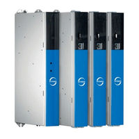
Stober SI6A262 multi-axis servo drives Manuals
Manuals and User Guides for Stober SI6A262 multi-axis servo drives. We have
1
Stober SI6A262 multi-axis servo drives manual available for free PDF download: Manual
Stober SI6A262 Manual (264 pages)
Multi-axis drive system
Brand:
Stober
| Category:
DC Drives
| Size: 11 MB
Table of Contents
Multi-Axis Drive System with Si6 and Ps6 Manual
2
Table of Contents
2
1 Foreword
9
2 User Information
10
Storage and Transfer
10
Described Product Type
10
Timeliness
10
Original Language
10
Limitation of Liability
10
Formatting Conventions
11
Use of Symbols
11
Markup of Text Elements
12
Conventions for Cables
13
Symbols, Marks and Test Symbols
13
Trademarks
14
3 General Safety Instructions
15
Directives and Standards
15
Qualified Personnel
15
Intended Use
15
Transport and Storage
16
Operational Environment and Operation
16
Working on the Machine
17
Tab. 1 Maximum Symmetrical Nominal Short-Circuit Current of the Supply Module
17
Disposal
18
Firefighting
18
4 UL-Compliant Use
19
5 System Configuration
22
Fig. 1 System Overview for the Multi-Axis Drive System with SI6 and PS6
22
Hardware Components
23
Supply Module
23
Fig. 2 PS6A24 Nameplate
23
Tab. 2 Meaning of the Specifications on the PS6 Nameplate
24
Tab. 3 Example Code for the PS6 Type Designation
25
Tab. 4 Meaning of the PS6 Example Code
25
Tab. 5 Available PS6 Types and Sizes
25
Drive Controller
27
Fig. 3 SI6A061 Nameplate
27
Fig. 4 Sticker with MV and Serial Number
28
Tab. 6 Meaning of the Specifications on the SI6 Nameplate
28
Tab. 7 Meaning of the Specifications on the Sticker
28
Tab. 8 Example Code for the SI6 Type Designation
29
Tab. 9 Meaning of the SI6 Example Code
29
Tab. 10 Available SI6 Types and Sizes
29
DC Link Connection
31
Controller
32
Operating Motors, Encoders and Brakes
33
Accessories
34
Software Components
37
Project Configuration and Parameterization
37
Applications
37
6 Technical Data
38
General Technical Data
38
Tab. 11 Device Features
38
Tab. 12 Transport and Storage Conditions
38
Tab. 13 Operating Conditions
38
Tab. 14 Discharge Times of the DC Link Circuit
38
Supply Module
39
Electrical Data
39
Tab. 15 Control Unit Electrical Data
39
Tab. 16: PS6 Electrical Data, Size 2
40
Tab. 17: PS6 Electrical Data, Size 3
40
Tab. 18 Electrical Data for Parallel Connection: Example Combinations
40
Tab. 20 Electrical Data
40
Tab. 19 Brake Chopper Electrical Data
41
Dimensions
42
Weight
42
Fig. 5 PS6 Dimensional Drawing
42
Tab. 21 PS6 Dimensions [MM]
42
Tab. 22 PS6 Weight [G]
42
Drive Controllers
43
Electrical Data
43
Tab. 23 Control Unit Electrical Data
43
Tab. 24 SI6 Electrical Data, Size 0
43
Tab. 25 SI6 Electrical Data, Size 0, at 4 Khz Clock Frequency
43
Tab. 26 SI6 Electrical Data, Size 0, at 8 Khz Clock Frequency
43
Tab. 27 SI6 Electrical Data, Size 1
44
Tab. 28 SI6 Electrical Data, Size 1, at 4 Khz Clock Frequency
44
Tab. 29 SI6 Electrical Data, Size 1, at 8 Khz Clock Frequency
44
Tab. 30 SI6 Electrical Data, Size 2
45
Tab. 31 SI6 Electrical Data, Size 2, at 4 Khz Clock Frequency
45
Tab. 32 SI6 Electrical Data, Size 2, at 8 Khz Clock Frequency
45
Tab. 33 SI6 Electrical Data, Size 3
46
Tab. 34 SI6 Electrical Data, Size 3, at 4 Khz Clock Frequency
46
Tab. 35 SI6 Electrical Data, Size 3, at 8 Khz Clock Frequency
46
Tab. 36 X101 Electrical Data
47
Tab. 37 X103 Electrical Data
47
Fig. 6 Asymmetric Load on Double-Axis Controllers
48
Tab. 38 Power Loss Data in Accordance with en 50598 for One Axis of a SI6 Drive Controller
49
Derating
51
Tab. 39 Absolute Losses in the Accessories
51
Tab. 40 Nominal Output Current I2N,PU Dependent on the Clock Frequency
51
Dimensions
53
Fig. 7 SI6 Dimensional Drawing
53
Tab. 41 SI6 Dimensions [MM]
53
Weight
54
DC Link Connection
54
General Technical Data
54
Tab. 42 SI6 Weight [G]
54
Tab. 43 Device Features
54
Tab. 44 Transport and Storage Conditions
54
Tab. 45 Operating Conditions
54
DL6B Assignment - SI6 and PS6
55
Dimensions
55
Fig. 8 DL6B Dimensional Drawing
55
Tab. 46 DL6B Assignment for SI6 and PS6
55
Weight
56
Tab. 47 DL6B Dimensions [MM]
56
Tab. 48 DL6B Weight [G]
56
Safety Technology
57
Tab. 49 X12 Electrical Data for SR6 Option
57
Operating Motors
58
Tab. 50 Motor Types and Control Modes
58
Evaluable Encoders
59
Overview
59
Signal Transmission
59
Tab. 51 Overview of Encoder Connection
59
Tab. 52 Endat 2.1 Digital Specification
60
Tab. 53 Endat 2.2 Digital Specification
60
Tab. 54 SSI Specification
61
Tab. 55 Specification for TTL Differential Incremental Signals
61
Tab. 56 Specification for Resolver Signals
62
Tab. 57 Specification for HIPERFACE DSL
62
Tab. 58 Encoder Models with Unsuitable Supply Voltage Range
62
X101 for Encoders
63
X103 for Encoders
63
Tab. 59 Specification for Single-Ended HTL Incremental Signals and Single-Ended HTL Pulse Train Signals
63
Tab. 60 Specification for Single-Ended HTL Incremental Signals and Single-Ended HTL Pulse Train Signals
63
Controllable Brakes
64
Tab. 61 Electrical Data of the Brake Output
64
Braking Resistor
65
Braking Resistor Assignment - PS6
65
KWADQU Flat Resistor
65
Tab. 62 Braking Resistor Assignment to PS6 Supply Module
65
Tab. 63 KWADQU 420×91 Specification
65
Fig. 9 KWADQU 420×91 Dimensional Drawing
66
Tab. 64 KWADQU 420×91 Dimensions [MM]
66
FZZMQU Tubular Fixed Resistor
67
Tab. 65 Specification for FZZMQU 400×65
67
Tab. 66 FZMU Conductor Cross-Section, FZZM(Q)U 400×65
67
Fig. 10 FZZMQU 400×65 Dimensional Drawing
68
Tab. 67 FZZMQU 400×65 Dimensions [MM]
68
FGFKQU Steel-Grid Fixed Resistor
69
Tab. 68 Specification for FGFKQU 31005
69
Tab. 69 FGFK(Q)U Conductor Cross-Section
69
Fig. 11 FGFKQU 31005 Dimensional Drawing
70
Tab. 70 FGFKQU 31005 Dimensions [MM]
70
Choke
71
TEP Output Choke
71
Tab. 71 Specification for TEP
71
Fig. 12 Derating the Nominal Current Depending on the Clock Frequency
72
Fig. 13 Derating the Nominal Current Depending on the Clock Frequency
72
Fig. 14 Derating the Nominal Current Depending on the Clock Frequency
73
Fig. 15 Derating the Nominal Current Based on Surrounding Temperature
73
Fig. 16 Derating the Nominal Current Depending on Installation Elevation
74
Fig. 17 Derating the Voltage Depending on Installation Elevation
74
Fig. 18 TEP Dimensional Drawing
75
Tab. 72 TEP Dimensions and Weight
75
7 Project Configuration
76
Supply Module
76
Information on Design and Operation
76
Parallel Connection of Supply Modules
77
Tab. 73 Electrical Data for Parallel Connection: Example Combinations
77
DC Link Connection
78
Information on Design and Operation
78
Mixed Operation
79
Fig. 19 Grounding Concept in Mixed Operation with Powered PS6 Supply Module
79
Example Design for UL-Compliant Operation
80
Tab. 74 Maximum Charging Capacity of the PS6 Supply Module
80
Tab. 75 Self-Capacitance of the SI6 Drive Controllers Connected to the PS6 Supply Module
80
Maximum Operation on PS6A24
81
Tab. 76 Maximum Operation on One PS6A24 Supply Module with DL6B20 Rear Section Module
81
Maximum Operation on PS6A34
82
Tab. 77 Maximum Operation on One PS6A34 Supply Module with DL6B21 Rear Section Module
82
Sample Calculation
83
Order Overview of the Hardware Components
83
Tab. 78 Overview of Hardware Components with ID no
83
8 Storage
85
Supply Module
85
Drive Controller
85
Annual Reforming
86
Fig. 20 Annual Reforming
86
Reforming before Commissioning
87
Fig. 21 Reforming before Commissioning
87
Fig. 22 Voltage Levels Dependent on Storage Time
88
9 Installation
89
Safety Instructions for Installation
89
Basic Assembly Instructions
89
Drive Controllers and Supply Modules
89
Fig. 23 Fields for Equipment Identification on the Front of the Device
89
Choke
90
Braking Resistor
90
Minimum Clearances
92
Fig. 24 Minimum Clearances
92
Tab. 79 Minimum Clearances [MM]
92
Drilling Diagrams and Dimensions
93
Multi-Axis Drive System
93
Fig. 25 Drilling Diagram for Multi-Axis Drive System
93
Tab. 80 Drilling Dimensions for the Multi-Axis Drive System [MM]
93
Length of Copper Rails
94
Fig. 26 Determination of the Correct Length of the Copper Rails
94
Installing the DC Link Connection
95
Order Overview of the Components for the DC Link Connection
95
Tab. 81 Overview of Hardware Components Necessary for the DC Link Connection with ID no
95
Installing Drive Controllers and Supply Modules
99
10 Connection
102
Safety Instructions for Connection
102
Line Routing
103
Protective Measures
103
Power Grid Supply
103
CE-Compliant Line Fuse
104
Tab. 82 PS6 Protective Devices
104
UL-Compliant Line Fuse
105
Grid Connection
105
Residual Current Protective Device
105
Tab. 83 UL-Compliant Line Fuse
105
CE-Compliant Housing Grounding
107
Fig. 27 Connection of the Grounding Conductor
107
Tab. 84 Minimum Cross-Section of the Grounding Conductor
107
UL-Compliant Housing Grounding
108
Fig. 28 Connection of the Grounding Conductor
108
EMC Recommendations
109
Supply Module
110
Overview
110
Fig. 29 Connection Overview Using the Example of the PS6A34
110
X10: 400 V Supply
111
Tab. 85 X10 Connection Description - Size 2
111
Tab. 86 X10 Connection Description - Size 3
111
X11: 24 V Supply
112
Tab. 87 Control Unit Electrical Data
112
Tab. 88 X11 Connection Description
112
X21: Braking Resistor
113
X22: DC Link Connection
113
Tab. 90 X21 Connection Description
113
Tab. 91 X22 Connection Description, Size 2
113
Tab. 92 X22 Connection Description, Size 3
113
X23: Temperature Monitoring of Braking Resistor
114
X100: Status Output
114
Tab. 93 X23 Connection Description
114
Tab. 94 X100 Connection Description
114
Connecting the Supply Module
115
Drive Controller
116
Overview
116
Fig. 30 Connection Overview Using the Example of the SI6A162
116
X2A: Brake a
117
Tab. 96 X2A Connection Description, Brake A, Sizes 0 to 2 (Single-Axis Controllers)
117
Tab. 97 X2A Connection Description, Brake A, Sizes 2 (Double-Axis Controllers) and 3
117
Tab. 98 Maximum Cable Length of the Power Cable [M]
117
X2A: Motor Temperature Sensor a
118
Tab. 99 X2A Connection Description, Motor Temperature Sensor A, Sizes 0 to 2 (Single- Axis Controller)
118
Tab. 100 X2A Connection Description, Motor Temperature Sensor A, Sizes 2 (Double-Axis Controller) and 3
118
X2B: Brake B
119
X2B: Motor Temperature Sensor B
119
X4A: Encoder a
119
Tab. 101 Maximum Cable Length of the Power Cable [M]
119
Tab. 102 X4A Connection Description for Endat 2.2 Digital Encoders and SSI Encoders
120
Tab. 103 X4A Connection Description for Differential TTL and Differential HTL (HTL over HT6 Adapter) Incremental Encoders
121
Tab. 104 X4A Connection Description for Resolvers
122
Tab. 105 X4A Connection Description for HIPERFACE DSL Encoders
122
Tab. 106 Cable Length [M]
123
Tab. 107 Encoder Models with Unsuitable Input Voltage Range
123
Tab. 108 Connection Description of AP6A00 for Resolver (9-Pin to 15-Pin)
123
X4B: Encoder B
124
X9: Ethernet Service Interface
124
Tab. 109 X9 Connection Description
124
Tab. 110 Cable Length [M]
124
X11: 24 V Supply
125
Tab. 112 Control Unit Electrical Data
125
Tab. 113 X11 Connection Description
125
Tab. 114 Cable Length [M]
125
X12: Safety Technology (SR6 Option)
126
Tab. 115 X12 Connection Description
126
Tab. 116 Cable Length [M]
126
X20A: Motor a
127
Tab. 117 X20A Connection Description, Size 0
127
Tab. 118 X20A Connection Description, Sizes 1 and 2 (Single-Axis Controllers)
127
Tab. 119 X20A Connection Description, Sizes 2 (Double-Axis Controllers) and 3
127
X20B: Motor B
128
X22: DC Link Connection
128
Tab. 120 Maximum Cable Length of the Power Cable [M]
128
Tab. 121 X22 Connection Description, Size 0
128
Tab. 122 X22 Connection Description, Sizes 1 and 2 (Single-Axis Controllers)
129
Tab. 123 X22 Connection Description, Sizes 2 (Double-Axis Controllers) and 3
129
10.5.14 X101: Be1 - Be4
130
Tab. 124 X101 Connection Description for Binary Signals
130
Tab. 125 X101 Connection Description for Single-Ended HTL Incremental Signals, Axis a
130
Tab. 126 X101 Connection Description for Single-Ended HTL Pulse/Direction Signals, Axis a
130
10.5.15 X103: Be6 - Be9
131
Tab. 89 Cable Length [M]
131
Tab. 111 Cable Requirements
131
Tab. 127 Cable Length [M]
131
Tab. 128 X103 Connection Description for Binary Signals
131
Tab. 129 X103 Connection Description for Single-Ended HTL Incremental Signals, Axis B
131
Tab. 95 Cable Length [M]
132
Tab. 130 X103 Connection Description for Single-Ended HTL Pulse/Direction Signals, Axis B
132
Tab. 131 Cable Length [M]
132
10.5.16 X200, X201: Ethercat
133
Tab. 132 X200 and X201 Connection Description
133
10.5.17 X200, X201: Profinet
134
Tab. 133 X200 and X201 Connection Description
134
10.5.18 X300: Brake 24 V Supply
135
X700: SD Slot
136
10.5.20 Connecting a Drive Controller
137
Output Choke
138
Connection Description
138
Fig. 31 TEP Output Choke Connection Example
139
Fig. 32 Shielded Connection of the Power Cable (Graphics: Icotek Gmbh)
139
Cables
140
Power Cables
141
Encoder Cables
145
One Cable Solution
155
11 Commissioning
159
Initiating the Project
159
Projecting the Drive Controller and Axis
159
Configuring the Safety Module
161
Creating Other Modules and Drive Controllers
161
Specifying a Module
161
Specifying the Project
162
Mechanical Drive Model
162
Parameterizing the STOBER Motor
162
Parameterizing the Axis Model
163
Testing the Project Configuration
165
12 Communication
167
System Requirements
167
Personal Firewall
167
Protocols and Ports for Communication Using Routers
168
Direct Connection
168
Fieldbus
168
13 Diagnostics
169
Supply Module
169
Drive Controller
172
Fieldbus State
173
Fsoe State
175
Drive Controller State
176
Service Network Connection
178
Fieldbus Network Connection
179
Events
181
Overview
181
Event 31: Short/Ground
183
Event 32: Short/Ground Internal
183
Event 33: Overcurrent
184
Event 34: Hardware Fault
185
Event 35: Watchdog
185
Event 36: High Voltage
186
Event 37: Motor Encoder
186
Event 38: Temperature Drive Controller Sensor
189
13.3.10 Event 39: Overtemperature Drive Controller I2T
190
13.3.11 Event 40: Invalid Data
191
13.3.12 Event 41: Temp.motortmp
192
Event 44: External Fault 1
193
13.3.14 Event 45: Overtemp.motor I2T
194
13.3.15 Event 46: Low Voltage
195
13.3.16 Event 47: Torque Limit
196
13.3.17 Event 50: Safety Module
197
13.3.18 Event 51: Virtual Master Limit Switch
198
13.3.19 Event 52: Communication
199
13.3.20 Event 53: Limit Switch
200
13.3.21 Event 54: Following Error
201
13.3.22 Event 56: Overspeed
202
13.3.23 Event 57: Runtime Usage
203
13.3.24 Event 59: Overtemperature Drive Controller I2T
204
Event 60: Application Event 0 - Event 67: Application Event 7
205
Event 68: External Fault 2
206
13.3.27 Event 69: Motor Connection
207
13.3.28 Event 70: Parameter Consistency
208
13.3.29 Event 71: Firmware
209
13.3.30 Event 72: Brake Test Timeout
210
13.3.31 Event 76: Position Encoder
211
13.3.32 Event 77: Master Encoder
214
13.3.33 Event 78: Position Limit Cyclic
217
13.3.34 Event 79: Motor / Position Monitor
218
13.3.35 Event 80: Illegal Action
219
13.3.36 Event 81: Motor Allocation
219
13.3.37 Event 85: Excessive Jump in Reference Value
220
13.3.38 Event 86: Unknown Data Record Leanmotor
221
13.3.39 Event 87: Reference Lostreference Loss
222
13.3.40 Event 88: Control Panel
223
13.3.41 Event 89: Maximum Current Lm
224
14 Replacement
225
Safety Instructions for Device Replacement
225
Replacing the Drive Controller
226
Exchanging the Supply Module
227
Replacing or Updating the Firmware
228
Changing the Fieldbus
228
15 Service
229
STOBER Electronics Service
229
Reverse Documentation
229
Creating Reverse Documentation in a New Project
229
Loading Reverse Documentation in an Existing Project
230
16 Appendix
231
Terminal Specifications
231
Overview
231
Fmc 1,5 -St-3,5
232
Bcf 3,81 180 Sn
233
Bfl 5.08Hc 180 Sn
233
Bldf 5.08 180 Sn
234
Gfkc 2,5 -St-7,62
235
Ispc 5 -Stgcl-7,62
236
Spc 5 -St-7,62
236
Spc 16 -St-10,16
237
16.1.13 Buz 10.16It 180 Mf
238
Wiring Examples
239
Operation with 1 Supply Module
239
Parallel Connection
240
UL-Compliant Connection of the Supply Module
241
Device Addressing
242
Drivecontrolsuite
243
System Requirements
243
Installation Types
243
Installing Software
244
Updates
244
Detailed Information
245
Symbols in Formulas
246
Abbreviations
248
17 Contact
249
Consultation, Service and Address
249
Close to Customers Around the World
250
Glossary
251
List of Figures
254
List of Tables
256
Advertisement
Advertisement
Related Products
Stober SI6A361
Stober SI6 Series
Stober SI6A061
Stober SI6A062
Stober SI6A261
Stober SI6A161
Stober SI6A162
Stober SD6A06
Stober SD6A14
Stober SD6A38
Stober Categories
Engine
Controller
Inverter
DC Drives
Industrial Equipment
More Stober Manuals
Login
Sign In
OR
Sign in with Facebook
Sign in with Google
Upload manual
Upload from disk
Upload from URL