
Subscribe to Our Youtube Channel
Related Manuals for Stober SI6 Series


Summary of Contents for Stober SI6 Series
- Page 1 Multi-axis drive system with SI6 and PS6 Manual stober.com en-US 07/2016 ID 442728.00...
-
Page 2: Table Of Contents
Table of contents STOBER Table of contents 1 Foreword .......................... 6 2 User information........................ 7 2.1 Storage and transfer ....................... 7 2.2 Described product type.................... 7 2.3 Original language...................... 7 2.4 Limitation of liability...................... 7 2.5 Conventions of representation.................. 8 2.5.1... - Page 3 STOBER Table of contents 5.2.2 Dimensions ....................... 29 5.2.3 Weight....................... 29 5.3 Drive controller...................... 30 5.3.1 Electrical data .................... 30 5.3.2 Derating ...................... 35 5.3.3 Dimensions ....................... 37 5.3.4 Weight....................... 38 5.4 DC link connection...................... 38 5.4.1 Electrical data .................... 38 5.4.2 Dimensions ....................... 40 5.4.3 Weight....................... 41 5.5 Operating motors ...................... 42 5.6 Braking resistor......................
- Page 4 9.1 Apply project ....................... 109 9.1.1 Project drive controller and axis.............. 109 9.1.2 Create other modules and drive controllers ............ 111 9.1.3 Specify module .................... 111 9.1.4 Specify project .................... 111 9.2 Map mechanical drive model .................. 112 9.2.1 Parameterize STOBER standard motor............ 112 9.2.2 Parameterize axis model ................ 112...
- Page 5 STOBER Table of contents 9.3 Test project configuration and basic functions............ 114 9.3.1 Test project configuration................ 114 9.3.2 Test basic functions .................. 116 10 Diagnostics ........................ 117 10.1 Supply module ...................... 117 10.2 Drive controller...................... 120 10.2.1 Fieldbus device state .................. 121 10.2.2 FSoE state ...................... 122 10.2.3 State of the drive controller ................ 123...
-
Page 6: Foreword
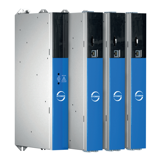
STOBER Foreword The completely new designed STOBER multi-axis drive system consists of the SI6 drive controller and PS6 supply module combination. The SI6 drive controller is available in three sizes as a single or double axis controller with a nominal output current of up to 22 A. The PS6 supply module is available in two sizes with a nominal output of 10 kW or 20 kW. -
Page 7: User Information
You will also find information for wiring the modules correctly and checking their functionality in the group with an initial test. Combinations with other drive controllers of the 6th STOBER generation of drive controllers are possible under certain general conditions. -
Page 8: Conventions Of Representation
2 | User information STOBER Conventions of representation To be able to quickly allocate particular information in this documentation, it is highlighted by orientation guides in the form of signal words, symbols and special text markups. 2.5.1 Use of symbols Safety instructions are identified with the following symbols. -
Page 9: Text Display
STOBER 2 | User information 2.5.2 Text display Certain text elements are featured as follows to facilitate orientation. Text Words or expressions with a special meaning Text Window names, dialog names, page names or buttons, composed proper nouns, functions cited by the interface... -
Page 10: Trademarks
2 | User information STOBER Trademarks The following names that are used in conjunction with the device, its optional equipment and its accessories are trademarks or registered trademarks of other companies: ® ® ® EnDat EnDat and the EnDat logo are registered trademarks of Dr. -
Page 11: General Safety Instructions
The connection of other electronic loads constitutes improper use! The PS6 supply module is intended for the supply of one or more drive controllers. Only drive controllers of the 6th generation of STOBER drive controllers may be connected to the PS6. -
Page 12: Transport And Storage
§ Use in environments with harmful substances as specified by EN 60721, for example oils, acids, gases, vapors, dust and radiation Implementation of the following applications is only permitted after approval from STOBER: § Use in non-stationary applications Working on the machine Apply the 5 safety rules in the order stated before performing any work on the machine: §... -
Page 13: Disposal
STOBER 3 | General safety instructions Disposal Observe the current national and regional regulations when disposing of the product! Dispose of the individual product parts depending on their properties, e.g. as: § Electronic waste (circuit boards) § Plastic § Sheet metal §... -
Page 14: System Configuration
4 | System configuration STOBER System configuration The multi-axis drive system consists of at least one PS6 supply module and one SI6 drive controller. For the energy supply of the existing drive controllers in the group, you need suitable Quick DC-Link modules for the DC link connection for each supply module and for each drive controller. -
Page 15: Hardware Components
STOBER 4 | System configuration Hardware components Below you will gain an overview of the available hardware components. 4.1.1 Supply module The PS6 supply module is available in two sizes. The type specifications used in this manual refer to the nameplate that is placed on the side of the supply module. -
Page 16: Tab. 1 Meaning Of The Specifications On The Ps6 Nameplate
4 | System configuration STOBER Designation Value in the example Meaning Type PS6A24 Device type according to type designation ID no. 56650 Identification number 003 HD Production information Date 1602 Production week in format YYWW, in the example shown here year 2016, week 2... -
Page 17: Fig. 3: Ps6 In Sizes 2 And 3
STOBER 4 | System configuration 4.1.1.3 Sizes Type ID no. Size PS6A24 56650 Size 2 PS6A34 56651 Size 3 Tab. 4: Available PS6 types and sizes Fig. 3: PS6 in sizes 2 and 3 Note that the basic device is delivered without terminals. Suitable terminal strips are available separately for each size. -
Page 18: Drive Controller
4 | System configuration STOBER 4.1.2 Drive controller The SI6 drive controller is available in three sizes as a single or double axis controller. In additional different safety options are available. The type specifications used in this manual refer to the nameplate that is placed on the side of the drive controller. -
Page 19: Tab. 5 Meaning Of The Specifications On The Si6 Nameplate
STOBER 4 | System configuration Designation Value in the example Meaning Type SI6A061Z Device type according to type designation ID no. 56645 Identification number of the basic device 003 HD Production information Date 1602 Production week in format YYWW, in the... -
Page 20: Fig. 5: Si6 In Sizes 0, 1 And 2
4 | System configuration STOBER 4.1.2.3 Sizes Type ID no. Size SI6A061 56645 Size 0 SI6A062 56646 Size 0 SI6A161 56647 Size 1 SI6A162 56648 Size 1 SI6A261 56649 Size 2 Tab. 8: Available SI6 types and sizes Fig. 5: SI6 in sizes 0, 1 and 2 Note that the basic device is delivered without terminals. -
Page 21: Dc Link Connection
DC link connection Via the Quick DC-Link modules, connect the DC link capacitors of several devices from the 6th STOBER generation of drive controllers is not permitted. For the horizontal connection, you receive the DL6B substructures in different designs, suitable for the size of the drive controller or supply module. -
Page 22: Controller
2 pcs. 4.1.4 Controller The development of the MC6 Motion Controller and its integration into the STOBER product portfolio opens up new solutions for drive technology, especially for complex functions with demanding requirements for timing and precision. The SI6 drive controller is connected via EtherCAT with the MC6. -
Page 23: Operating Motors, Encoders And Brakes
Referencing and jog are performed with jerk limitation during commissioning. Whenever universal and flexible solutions are necessary, the drive-based application package from STOBER is the appropriate choice. For the STOBER Drive Based application, a drive- based movement controller for positioning, velocity and torque/force is provided with the PLCopen Motion Control command set. -
Page 24: Safety Technology
4 | System configuration STOBER Safety technology The safety modules are used to realize the STO safety function. They prevent the generation of a rotary field in the power output stage of the drive controller. For an external requirement or in the event of error, the safety module switches the drive controller to the STO state. -
Page 25: Communication
STOBER 4 | System configuration Communication The SI6 drive controller has two interfaces for the EtherCAT connection on the top of the device as well as via an Ethernet service interface on the front of the device. Cables for the connection are available separately. -
Page 26: Technical Data
5 | Technical Data STOBER Technical Data Technical data for supply modules, drive controllers and available accessories can be found in the following sections. Common technical data The following specifications apply equally for the SI6 drive controller and the PS6 supply module. -
Page 27: Supply Module
STOBER 5 | Technical Data Supply module The following section contains specifications for the electrical data, dimensions and weight of the PS6 supply module. 5.2.1 Electrical data The electrical data of the available PS6 sizes as well as the properties of the brake chopper can be found in the following sections. -
Page 28: Tab. 15 Electrical Data: Ps6A34
5 | Technical Data STOBER 5.2.1.4 Parallel operation Information In case of parallel operation of supply modules, the power is increased but not the charging capacity. Electrical data 2 x PS6A24 3 x PS6A24 2 x PS6A34 3 x PS6A34 16 kW... -
Page 29: Fig. 6 Dimension Drawing Ps6
STOBER 5 | Technical Data 5.2.2 Dimensions Fig. 6: Dimension drawing PS6 Dimension Size 2 Size 3 Supply module Body height Fastening clip height Height incl. fastening clips Width Depth Fastening holes Vertical distance 360+2 Vertical distance to upper edge Tab. 18: Dimensions PS6 [mm] 5.2.3... -
Page 30: Electrical Data
5 | Technical Data STOBER Drive controller The following section contains specifications for the electrical data, dimensions and weight of the SI6 drive controller. 5.3.1 Electrical data The electrical data of the available SI6 sizes can be found in the following sections. -
Page 31: Tab. 24 Electrical Data: Si6A1Xx
STOBER 5 | Technical Data 5.3.1.3 Power unit: size 1 Electrical data SI6A161 SI6A162 280 – 800 V 0 – 700 Hz 0 – max. Tab. 24: Electrical data: SI6A1xx Nominal currents up to +45 °C (in the control cabinet) Electrical data SI6A161 SI6A162 4 kHz PWM,PU 12 A 2 × 12 A 2N,PU 210 % for 2 s... -
Page 32: Tab. 27 Electrical Data: Si6A2Xx
5 | Technical Data STOBER 5.3.1.4 Power unit: size 2 Electrical data SI6A261 280 – 800 V 0 – 700 Hz 0 – max. Tab. 27: Electrical data: SI6A2xx Nominal currents up to +45 °C (in the control cabinet) Electrical data SI6A261 4 kHz PWM,PU 22 A 2N,PU 210 % for 2 s 2maxPU Tab. -
Page 33: Tab. 30 Power Loss Data According To En 50598 For An Axis Of A Si6 Drive Controller
STOBER 5 | Technical Data 5.3.1.5 Power loss data according to EN 50598 Type Nominal Apparent Absolute Working points Comparison current power losses class 2N,PU V,CU (0/25) (0/50) (0/100) (50/25) (50/50) (50/100) (90/50) (90/100) Relative losses [kVA] SI6A06x Max. 10 0.71... - Page 34 5 | Technical Data STOBER General conditions The specified losses apply for an axis of a drive controller and take into account the proportionate losses of the PS6 supply module for this axis. For a group with a total of x axes, the values are then to be multiplied by the number of the axis controllers (x), e.g. x = 4 for 1 × PS6 and 2 × SI6A062.
-
Page 35: Derating
STOBER 5 | Technical Data 5.3.2 Derating When dimensioning the drive controller, observe the derating of the nominal output current depending on the clock frequency, surrounding temperature, and installation altitude. There is no restriction for a surrounding temperature from 0 °C to 45 °C and an installation altitude of 0 m to 1000 m. - Page 36 5 | Technical Data STOBER Example The drive controller will be installed at an altitude of 1500 m above sea level. The derating factor D is calculated as follows: = 100 % − 5 × 1.5 % = 92.5 % 5.3.2.4 Calculating the derating Follow these steps for the calculation: 1.
-
Page 37: Fig. 7 Dimension Drawing Si6
STOBER 5 | Technical Data 5.3.3 Dimensions Fig. 7: Dimension drawing SI6 Dimension Size 0 Size 1 Size 2 Drive controller Body height Fastening clip height Height incl. fastening clips Total height incl. shield connection Width Depth Fastening holes Vertical distance... -
Page 38: Weight
5 | Technical Data STOBER 5.3.4 Weight Weight SI6A061 SI6A062 SI6A161 SI6A162 SI6A261 Without packaging 3.0 kg 3.5 kg 3.9 kg 4.9 kg 4.8 kg With packaging 4.6 kg 5.1 kg 5.3 kg 6.3 kg 6.2 kg Tab. 33: Weight SI6 DC link connection The following section contains specifications for the electrical data, dimensions and weight of the DL6B Quick DC-Link modules. -
Page 39: Tab. 36 Electrical Data Supply Module
STOBER 5 | Technical Data Size Type Charging capacity 1N,PU [µF] Size 2 PS6A24 3 × 400 5000 Size 3 PS6A34 3 × 400 10000 Tab. 36: Electrical data supply module Information In cyclic power on/off operation a cycle time of 30 s is important to note to prevent the load capacities of the supply modules overloading. -
Page 40: Dimensions
5 | Technical Data STOBER 5.4.2 Dimensions Fig. 8: Dimension drawing DL6B Dimension DL6B10 DL6B11 DL6B20 DL6B21 Quick DC-Link Height Fastening clip height Height incl. fastening clips Width Depth Depth incl. attachment bolts Fastening holes Vertical distance 393+2 (wall mounting) Vertical distance... -
Page 41: Weight
STOBER 5 | Technical Data 5.4.3 Weight Weight DL6B10 DL6B11 DL6B20 DL6B21 With / without packaging 0.5 kg 0.6 kg 0.6 kg 0.8 kg Tab. 38: Weight DL6B... -
Page 42: Operating Motors
5 | Technical Data STOBER Operating motors You can operate the following motors with the specified control modes on the drive controller. Motor type B20 Control mode Encoder Other settings Characteristics Synchronous 64: SSM - vector Resolver or Without field... -
Page 43: Braking Resistor
STOBER 5 | Technical Data Braking resistor The following section contains the technical data of suitable braking resistors of different designs and performance classes. 5.6.1 Flat resistor KWADQU 420x91 Properties Specification KWADQU 420x91 ID no. 56634 Type Flat resistor with temperature switch (incl. -
Page 44: Fig. 9 Dimension Drawing Kwadqu 420X91
5 | Technical Data STOBER Dimensions Dimension KWADQU 420x91 ID no. 56634 Tab. 41: Dimensions KWADQU 420x91 [mm] Fig. 9: Dimension drawing KWADQU 420x91 Assembly instructions Permitted assembly: § On vertical surfaces with cables downwards § On horizontal surfaces § Assembly outside of the control cabinet possible for... -
Page 45: Tubular Fixed Resistor Fzzmqu 400X65
STOBER 5 | Technical Data 5.6.2 Tubular fixed resistor FZZMQU 400x65 Properties Specification FZZMQU 400x65 ID no. 56635 Type Tubular fixed resistor with temperature switch Resistance [Ω] Power [W] 1200 Thermal time constant τ Pulse power for < 1 s [kW] Weight [kg] approx. -
Page 46: Fig. 10 Dimension Drawing Fzzmqu 400X65
5 | Technical Data STOBER Dimensions Dimension FZZMQU 400x65 ID no. 56635 L × D 400 × 65 6.5 × 12 Tab. 43: Dimensions FZZMQU 400x65 [mm] Fig. 10: Dimension drawing FZZMQU 400x65 Assembly instructions Permitted assembly: § On vertical surfaces with terminals downwards §... -
Page 47: Steel-Grid Fixed Resistor Fgfkqu 31005
STOBER 5 | Technical Data 5.6.3 Steel-grid fixed resistor FGFKQU 31005 Properties Specification FGFKQU 31005 ID no. 56636 Type Steel-grid fixed resistor with temperature switch Resistance [Ω] Power [W] 2500 Thermal time constant τ Pulse power for < 1 s [kW] Weight [kg] approx. -
Page 48: Fig. 11 Dimension Drawing Fgfkqu 31005
5 | Technical Data STOBER Dimensions Dimension FGFKQU 31005 ID no. 56636 Tab. 45: Dimensions FGFKQU 31005 [mm] Fig. 11: Dimension drawing FGFKQU 31005 Assembly instructions Permitted assembly: § On vertical surfaces with terminals downwards § Top and bottom perforated sheet §... -
Page 49: Output Choke
The motor temperature sensor evaluation is faulting due to cable capacitances. ▪ If you do not use a cable from STOBER for a cable length over 50 m, you must wire the motor temperature sensor and the brake separately (maximum length: 100 m). -
Page 50: Tab. 46 Specification Tep
5 | Technical Data STOBER Properties Specification TEP3720-0ES41 TEP3820-0CS41 TEP4020-0RS41 ID no. 53188 ID no. 53189 ID no. 53190 Voltage range 3 x 0 to 480 V Frequency range 0 – 200 Hz at 4 kHz 4 A 17.5 A 38 A at 8 kHz 3.3 A 15.2 A 30.4 A... -
Page 51: Fig. 12 Derating Tep3720-0Es41
STOBER 5 | Technical Data Derating I [A] f [Hz] Fig. 12: Derating TEP3720-0ES41 Cycle frequency 4 kHz Cycle frequency 8 kHz I [A] f [Hz] Fig. 13: Derating TEP3820-0CS41 Cycle frequency 4 kHz Cycle frequency 8 kHz... -
Page 52: Fig. 14 Derating Tep4020-0Rs41
5 | Technical Data STOBER I [A] f [Hz] Fig. 14: Derating TEP4020-0RS41 Cycle frequency 4 kHz Cycle frequency 8 kHz... -
Page 53: Fig. 15 Dimension Drawing Tep
STOBER 5 | Technical Data Dimensions and weight Dimension TEP3720-0ES41 TEP3820-0CS41 TEP4020-0RS41 Height h [mm] max. 153 max. 153 max. 180 Width w [mm] Depth d [mm] Vertical distance – fastening holes a1 [mm] Vertical distance – fastening holes a2 [mm] Horizontal distance –... -
Page 54: Bearing
6 | Bearing STOBER Bearing Store the products in a dry and dust-free room if you do not install them immediately. Observe the Transport and storage conditions [} 26] specified in the technical data. Supply module No forming is required for the PS6 supply module even after long storage times. -
Page 55: Yearly Forming
STOBER 6 | Bearing 6.2.1 Yearly forming To prevent damage to stored drive controllers, STOBER recommends connecting stored devices to the supply voltage once a year for one hour. The following graphic shows the principle supply connection. L1 L2 D- D+ D- D+ Fig. 16: Yearly forming... -
Page 56: Forming Before Commissioning
6 | Bearing STOBER 6.2.2 Forming before commissioning If forming every year is not possible, form the stored devices before commissioning. Note that the voltage levels depend on the storage time. The following graphic shows the principle supply connection. L1 L2... -
Page 57: Fig. 18 Voltage Levels Dependent On Storage Time
STOBER 6 | Bearing t [h] Fig. 18: Voltage levels dependent on storage time Storage time 1 – 2 years: Apply voltage for 1 hour before switching on. Storage time 2 – 3 years: Form the curve accordingly before switching on. Storage time ≥ 3 years: Form the curve accordingly before switching on. -
Page 58: Installation
7 | Installation STOBER Installation The following section describes the installation of the Quick DC-Link rear modules for the DC link connection as well as the subsequent installation of the drive controllers and supply modules. Safety instructions for installation Installation work is only admissible when no voltage is present. Observe the 5 safety rules. -
Page 59: Minimum Clearances
STOBER 7 | Installation Minimum clearances Note the minimum clearances for installation below. Minimum clearance A (above) B (below) C (on the side) All sizes Tab. 48: Minimum clearances for the multi-axis drive system [mm]... -
Page 60: Drilling Diagram And Dimensions
7 | Installation STOBER Drilling diagram and dimensions DL6B P S 6 S I6 S I6 Dimension Quick DC-Link DL6B10 46±1 393+2 ∅ 4.2 DL6B20 (M5) DL6B11 66±1 DL6B21 Tab. 49: Drilling dimensions for the multi-axis drive system [mm]... -
Page 61: Length Of Copper Rails
STOBER 7 | Installation Length of copper rails For the installation of the Quick DC-Link modules, you require 3 prepared copper rails with a cross-section of 5 × 12 mm. Plan the length of the copper rails slightly longer than the total length of the group, i.e. the total width of all DL6B Quick DC-Link modules present in the group. -
Page 62: Install Dc Link Connection
7 | Installation STOBER Install DC link connection DANGER! Electrical voltage! Danger to life due to electric shock! ▪ Always switch off all power supply voltage before working on the devices! ▪ Note the discharge time of the DC link capacitors. You can only determine the absence of voltage after this time period. -
Page 63: Install Drive Controllers And Supply Modules
STOBER 7 | Installation Install drive controllers and supply modules DANGER! Electrical voltage! Danger to life due to electric shock! ▪ Always switch off all power supply voltage before working on the devices! ▪ Note the discharge time of the DC link capacitors. You can only determine the absence of voltage after this time period. -
Page 64: Connection
8 | Connection STOBER Connection The following section describes the connection of the supply modules and drive controllers as well as the available accessories. Safety instructions for connection Installation work is only admissible when no voltage is present. Observe the 5 safety rules. -
Page 65: Protective Measures
STOBER 8 | Connection The protection class of the devices is protective grounding. Because of this, operation is only admissible if the protective ground wire is connected according to requirements. All protective ground connections are identified by “PE” or the international symbol for grounding (IEC 60417, symbol 5019). -
Page 66: Residual Current Protection Device
8.2.3 Residual current protection device STOBER devices can be protected with a Residual Current protective Device (RCD) to detect residual currents. Residual current protective devices prevent electrical accidents, especially ground fault through the body. They are generally distinguished according to their triggering limit and suitability for detecting different types of residual current. -
Page 67: Housing Grounding
STOBER 8 | Connection Information Check whether the use of residual current protective devices with increased trigger current as well as with short-time delayed or delayed switch-off trigger characteristics are permitted in your application. DANGER! Electric shock hazard! Stray and residual currents with a DC current component can restrict the functionality of residual current protective devices types A and AC. -
Page 68: Emc Recommendations
8 | Connection STOBER Cross-section A Minimum cross-section A Mains line Protective ground at earth bolt A ≤ 2.5 mm² 2.5 mm² 2.5 < A ≤ 16 mm² 16 – 35 mm² ≥ 16 mm² > 35 mm² Tab. 52: Minimum cross-section of the protective ground... -
Page 69: Supply Module
STOBER 8 | Connection Supply module Detailed information about the terminals of the supply module, correct connection as well as the general conditions for parallel operation of several supply modules can be found in the following sections. 8.4.1 Overview of terminals Fig. 21: Terminal overview using the example of the PS6A34... -
Page 70: X10: Supply 230 V/ 400 V
8 | Connection STOBER 8.4.2 X10: supply 230 V/ 400 V Terminal X10 is used to connect the supply module to the supply network. Electrical data All sizes 3 × 400 V , +32 % / -50 %, 50/60 Hz; 3 × 480 V , +10 % / -58 %, 50/60 Hz Tab. -
Page 71: X11: Supply 24 V
STOBER 8 | Connection 8.4.3 X11: supply 24 V The connection of 24 V to X11 is required for the supply of the control board. ATTENTION! Device damage due to overload! If the 24 vdc power supply is looped to multiple devices via the terminal, the terminal may be damaged by a current that is too high. -
Page 72: X21: Braking Resistor
8 | Connection STOBER 8.4.4 X21: braking resistor Terminal X21 is available for the connection of a braking resistor. Terminal Designation Function Braking resistor connection RB | RB Tab. 60: Terminal description X21 Connection type All sizes Rigid Flexible Flexible with cable end, without plastic sleeve Flexible with cable end, with plastic sleeve Tab. -
Page 73: X23: Temperature Monitoring Of Braking Resistor
STOBER 8 | Connection Terminal Designation Function DC link connection D- | D+ Tab. 63: Terminal description X22 – size 3 Connection type Size 2 Size 3 Rigid Flexible Flexible with cable end, without plastic sleeve Flexible with cable end, with plastic sleeve Tab. -
Page 74: X100: Status Output
8 | Connection STOBER 8.4.7 X100: status output The relay status output of terminal X100 in conjunction with the 3 diagnostic LEDs on the front of the device provides information about the status of the supply module. Electrical data Relay 30 V... -
Page 75: Connect Supply Module
STOBER 8 | Connection 8.4.8 Connect supply module DANGER! Electrical voltage! Danger to life due to electric shock! ▪ Always switch off all power supply voltage before working on the devices! ▪ Note the discharge time of the DC link capacitors. You can only determine the absence of voltage after this time period. -
Page 76: Connect Supply Modules In Parallel
Each supply module must be earthed to the earth bolt, see section Housing grounding [} 67]. § There are no restrictions for the position of a supply module within the group. § Mixed supply operation with drive controllers of the 6th STOBER generation of drive controllers is not permitted. -
Page 77: Fig. 22 Principle Circuit Diagram With Supply Modules Connected In Parallel
STOBER 8 | Connection Principal circuit diagram The following graphic shows the principle connection of 3 PS6 supply modules and several SI6 drive controllers based on the DC link connection with DL6B Quick DC-Link. L1 L2 L3 PE L1 L2... -
Page 78: Drive Controller
8 | Connection STOBER Drive controller The following section contains detailed information about the terminals and the correct connection of the drive controller. 8.5.1 Overview of terminals Fig. 23: Terminal overview using the example of the SI6A162 Top of the device... -
Page 79: X2A: Motor Holding Brake A
The motor holding brake of axis A is connected to X2A. All device types of the SI6 drive controller can control a 24 V brake as standard. Information Note that motor holding brakes from other manufacturers may only be connected after consultation with STOBER. Electrical data Brake output 24 – 30 V 2.5 A... -
Page 80: X2A: Motor Temperature Sensor A
8 | Connection STOBER 8.5.3 X2A: motor temperature sensor A The motor temperature sensor of axis A is connected to terminal X2A. All device types of the SI6 drive controller have connections for thermistors. You can connect a maximum of two PTC triplets to X2A. -
Page 81: X4A: Encoder A
STOBER 8 | Connection 8.5.6 X4A: encoder A The encoder of axis A is connected to terminal X4A. ATTENTION! Risk of encoder destruction! X4 may not be plugged in or unplugged when the device is switched on! ATTENTION! Risk of encoder destruction! Only encoders with a suitable input voltage range may be connected to X4. - Page 82 8 | Connection STOBER Specification 12 V (unregulated) 250 mA 2max Encoder type Single-turn and multiturn switching frequency 250 kHz Sampling rate 250 µs Code Binary or Gray Format 13, 24 oder 25 bits Transfer Double or single Max. cable length 100 m Tab. 78: SSI specification...
- Page 83 STOBER 8 | Connection Specification Resolver -10 V ... +10 V 80 mA 2max 7 – 9 kHz 0.8 W Transfer ratio 0.5 ± 5 % Number of poles 2, 4 and 6 Phase shift ± 20 el.° Maximum cable length 100 m Tab. 80: Specification resolver Specification HIPERFACE DSL 12 V (unregulated)
- Page 84 8 | Connection STOBER Terminal description according to encoder type Terminal Designation Function — — Reference for encoder supply to pin 4 Socket — — Encoder supply Data+ Differential input for DATA — — — — Clock+ Differential input for C:PCL —...
- Page 85 STOBER 8 | Connection Terminal Designation Function — — Reference for encoder supply to pin 4 Socket — — Encoder supply Differential input for B channel — — Differential input for N channel Differential input for A channel — —...
-
Page 86: X4B: Encoder B
Tab. 84: Terminal description X4A for resolver Information To ensure proper functionality, we recommend using cables from STOBER that are matched to the complete system. In case of use of unsuitable connection cables, we reserve the right to reject claims under the warranty. -
Page 87: X9: Ethernet Service Interface
Tab. 85: Terminal description X9 Information To ensure proper functionality, we recommend using cables from STOBER that are matched to the complete system. In case of use of unsuitable connection cables, we reserve the right to reject claims under the warranty. -
Page 88: X11: Supply 24 V
8 | Connection STOBER 8.5.9 X11: supply 24 V The connection of 24 V to X11 is required for the supply of the control board. ATTENTION! Device damage due to overload! If the 24 vdc power supply is looped to multiple devices via the terminal, the terminal may be damaged by a current that is too high. -
Page 89: X12: Safety Technology
STOBER 8 | Connection 8.5.10 X12: Safety technology Note: If you will be using the STO safety function via terminals, make certain to read the SR6 manual, see section Extensive documentation [} 127]. Designation / function Electrical data (bridged internally) = 30 V... -
Page 90: X20A: Motor A
Tab. 95: Maximum conductor cross-section [mm²] Information To ensure proper functionality, we recommend using cables from STOBER that are matched to the complete system. In case of use of unsuitable connection cables, we reserve the right to reject claims under the warranty. -
Page 91: X20B: Motor B
STOBER 8 | Connection Connection without output choke Note the following points for the connection of the power cable for a motor without output choke: § Ground the shield of the power cable on the shield contact on the drive controller intended for this. - Page 92 8 | Connection STOBER Tab. 97: Terminal description X22 – size 0 Terminal Designation Function DC link connection D- | D+ Tab. 98: Terminal description X22 – sizes 1 and 2 Connection type Size 0 Sizes 1 and 2 Rigid...
-
Page 93: X101: Be1 - 4
STOBER 8 | Connection 8.5.14 X101: BE1 – 4 The binary inputs 1 to 4 are available on terminal X101. Terminal Binary input Value Low level BE1 – 4 0 – 8 V High level 12 – 30 V 30 V 1max 16 mA 1max BE1 –... -
Page 94: X103: Be6 - 9
8 | Connection STOBER 8.5.15 X103: BE6 – 9 The binary inputs 6 to 9 are available on terminal X103. Electrical data Binary input Value Low level BE6 – 9 0 – 8 V High level 12 – 30 V 30 V 1max 16 mA... -
Page 95: X200, X201: Ethercat
Tab. 108: Terminal description X200 and X201 Information To ensure proper functionality, we recommend using cables from STOBER that are matched to the complete system. In case of use of unsuitable connection cables, we reserve the right to reject claims under the warranty. -
Page 96: X300: Supply 24 V Brake
128 MB to 32 GB are supported. SDHC cards with a memory capacity of 64 GB can only be used if they were previously reformatted to max. 32 GB. As higher capacitances increase the controller starting time, STOBER recommends the use of cards with a memory capacity of 2 to 4 GB. -
Page 97: Connect Drive Controller
STOBER 8 | Connection Information The SI6 drive controller has an internal configuration memory and can therefore be operated without an inserted SD card. In the DS6 commissioning software, the action A00Save values always saves in the internal configuration memory as well as on the inserted SD card. Back up your configuration on a SD card after commissioning is completed to be able to transfer the configuration to the replacement controller in the event of service. -
Page 98: Cable
When using a motor brake, pay attention to the voltage drop in the supply voltage on the lead. Information To ensure proper functionality, we recommend using cables from STOBER that are matched to the complete system. In case of use of unsuitable connection cables, we reserve the right to reject claims under the warranty. -
Page 99: Power Cable
Wire no. Motor, brake temperature sensor Synchronous servo motors from STOBER are equipped with circular plugs as a standard features. They can be connected to drive controllers with the following power cables. The color specifications refer to the connection wires and are only significant for the motor-internal wiring. -
Page 100: Tab. 115 Power Cable Pin Assignment Con.23
8 | Connection STOBER Bracket flange Designation Motor int. Wire Wire no. socket – Motor colors 1BD1 1BD2 1TP1/1K1 BK/BN 1TP2/1K2 WH/WH GN/YE Housing Shield — — Tab. 115: Power cable pin assignment con.23 Length [mm] Diameter [mm] Tab. 116: Dimensions con. 23... - Page 101 STOBER 8 | Connection BROWN BLUE VIOLET GREEN WHITE GREY YELLOW ORANGE Tab. 119: Cable color – key...
-
Page 102: Encoder Cable
STOBER 8.6.2 Encoder cable STOBER motors are equipped with encoder systems as standard. Depending on the respective motor types, different encoder systems and associated plug connectors are used. The following sections describe the individual encoder systems, plug connectors and signal assignments for connecting to STOBER drive controllers. -
Page 103: Tab. 120 Encoder Cable Pin Assignment Con.15
STOBER 8 | Connection Encoder cable – plug connector con.15 The voltage supply is buffered for the inductive EnDat 2.2 digital encoders "EBI 1135" and "EBI 135" with multiturn function. In this case, pin 2 and pin 3 are assigned to the backup battery . -
Page 104: Tab. 122 Encoder Cable Pin Assignment Con.17
8 | Connection STOBER Bracket flange Designation Wire colors Sub-D (X4) socket – Motor Motor int. Encoder Clock+ Sense 2BAT+ — 2BAT- — — — — Data- Data+ — — — — Clock- — — — — WH/GN — —... -
Page 105: Tab. 124 Encoder Cable Pin Assignment Con.23
STOBER 8 | Connection Encoder cable – plug connector con.23 Bracket flange Designation Wire colors Sub-D (X4) socket – Motor Motor int. Encoder Clock+ Sense BN/GN — — — — — — — — Data- Data+ — — — —... -
Page 106: Tab. 127 Encoder Cable Pin Assignment Con.15
8 | Connection STOBER 8.6.2.2 Resolver Suitable resolver cables are described below. con.15 con.17 Bracket flange socket motor STOBER encoder cable Sub-D (X4) Encoder cable – plug connector con.15 Bracket flange Designation Wire colors Sub-D (X4) socket – Motor Motor int. -
Page 107: Tab. 128 Dimensions Con. 15
STOBER 8 | Connection Length [mm] Diameter [mm] 18.7 Tab. 128: Dimensions con. 15 Encoder cable – plug connector con.17 Bracket flange Designation Wire colors Sub-D (X4) socket – Motor Motor int. Encoder S3 Cos+ S1 Cos- S4 Sin+ S2 Sin- —... -
Page 108: Tab. 131 Encoder Cable Pin Assignment Con.23
8 | Connection STOBER Encoder cable – plug connector con.23 Bracket flange Designation Wire colors Sub-D (X4) socket – Motor Motor int. Encoder S3 Cos+ S1 Cos- S4 Sin+ S2 Sin- — — — Do not connect — — —... -
Page 109: Commissioning
The following section includes the commissioning of your drive system with the application CiA 402 Controller Based. As regards the components of your drive model, we require a STOBER standard synchronous servo motor with EnDat encoder and integrated holding brake. These motors together with all... - Page 110 9 | Commissioning STOBER Device controller: Device controller tab: Select the device controller that defines the basic control signals of the drive controller. Process data Rx, process data Tx: If you control the drive controller via a fieldbus, select the fieldbus-specific receive and send process data.
-
Page 111: Create Other Modules And Drive Controllers
STOBER 9 | Commissioning 9.1.2 Create other modules and drive controllers We recommend sorting all drive controllers of your project in the DriveControlSuite either functionally according to groups and to combine a group under a module, or organizing several drive controllers based on their distribution to different control cabinets in corresponding modules. -
Page 112: Map Mechanical Drive Model
9.2.1 Parameterize STOBER standard motor You have projected a STOBER synchronous servo motor with EnDat encoder and integrated holding brake. 1. Mark the relevant drive controller in the project tree and click on the first projected axis in Project menu >... - Page 113 STOBER 9 | Commissioning 9.2.2.2 Scale axis 1. Mark the relelvant drive controller in the project tree and click on the first projected axis in Project menu > Section Wizard. 2. Select the Axis model > Scaling axis. 3. Scale the axis by configuring the overall transmission between the motor and output.
-
Page 114: Test Project Configuration And Basic Functions
9 | Commissioning STOBER 6. I10 Maximal velocity: Specify the calculated maximum velocity of the output. 7. Continue in the same way as for the maximum velocity and determine corresponding limit values for acceleration and jerk and enter in the associated parameters. - Page 115 STOBER 9 | Commissioning ð The Assignment window opens. Method column: Select Send to drive controller. In project column: Select the projected drive controller that you want to assign to the real drive controller from the project tree. 5. Click Start.
-
Page 116: Test Basic Functions
9 | Commissioning STOBER 9.3.2 Test basic functions The PLCopen control panel provides you with all PLCopen standard commands that can be used to test the plausibility of your parameterization, i.e. real basic functions and basic movements. 1. Mark the relevant drive controller in the project tree and click on the first projected axis in Project menu >... -
Page 117: Diagnostics
STOBER 10 | Diagnostics Diagnostics LEDs on the top and front give you initial information about the device state of the respective device as well as the states of the physical connection and the communication. In the event of an error or fault, you will receive detailed information via the DriveControlSuite commissioning software. -
Page 118: Tab. 134 Meaning Of The 3 Leds (Run, Error And Warning) On The Front Of The Ps6 Device
10 | Diagnostics STOBER Relay and LED state display Relay and LEDs always display the same state. The states are displayed using the priority list initialization/ready < Warning 1 < Warning 2 < Fault. The display of states with higher priority triggers the display of states with lower priority (example: warning 2 overwrites warning 1). - Page 119 STOBER 10 | Diagnostics LEDs: Behavior Description Relay Green/Red/ (X100): WARNING1 WARNING2 Yellow READY Fault: switch-on Open Closed Closed in the short- 5x flash circuited DC link Device is Open Open Open switched off Tab. 134: Meaning of the 3 LEDs (RUN, ERROR and WARNING) on the front of the PS6 device...
-
Page 120: Drive Controller
STOBER 10.2 Drive controller STOBER drive controllers have diagnostic LEDs that visualize the state of the drive controller as well as the states of the physical connection and the communication. FSoE Fig. 26: Positioning of the diagnostic LEDs on the front and top of the SI6 device. -
Page 121: Fieldbus Device State
STOBER 10 | Diagnostics 10.2.1 Fieldbus device state 2 LEDs on the front of the device provide information about the fieldbus device state. FSoE Fig. 27: LEDs for the fieldbus device state on the top of the SI6 device Red: ERROR... -
Page 122: Fsoe State
10 | Diagnostics STOBER 10.2.2 FSoE state If the drive controller has the option SY6 (STO via FSoE), a LED on the front of the device provides information about the FSoE state. This can be read in parameter S20 FSOE Status. -
Page 123: State Of The Drive Controller
STOBER 10 | Diagnostics 10.2.3 State of the drive controller 3 LEDs on the front of the device provide Information about the state of the drive controller. Fig. 29: LEDs for the state of the drive controller on the top of the SI6 device... - Page 124 10 | Diagnostics STOBER Flashing pattern for the firmware update The states of the green and red LEDs apply as described even during a live firmware update. In the following exceptional cases, the three LEDs flash in different combinations and frequencies:...
-
Page 125: Network Connection Service
STOBER 10 | Diagnostics 10.2.4 Network connection service The LEDs at terminal X9 on the front of the device display the state of the service network connection. Fig. 30: LEDs for the state of the service network connection on the top of the SI6 device... -
Page 126: Network Connection Fieldbus
10 | Diagnostics STOBER 10.2.5 Network connection fieldbus The LEDs LA IN and LA OUT at terminals X200 and X201 on the top of the device display the state of the network connection. Fig. 31: LEDs for the state of the network connection on the top of the SI6 device... -
Page 127: Annex
Project set-up, project 442708 Based (CiA DB) configuration, parameterization, function test, further information Application STOBER Manual Project set-up, project 442706 Drive Based (STOBER configuration, parameterization, function test, further information Safety technology SR6 – Manual Technical data, 442741 STO via terminals installation,... -
Page 128: Formula Symbol
11 | Annex STOBER 11.2 Formula symbol Formula Unit Explanation symbols Reduction of the nominal current depending on the installation height Reduction of the nominal current depending on the surrounding temperature Maximum input frequency 1max Output frequency of the power unit... -
Page 129: Abbreviations
STOBER 11 | Annex 11.3 Abbreviations Abbreviation Meaning Alternating Current American Wire Gauge Binäreingang (en.: binary input) Baugröße (en.: size) Computerized Numerical Control Direct Current Electromagnetic Compatibility EtherCAT Ethernet for Control Automation Technology FSoE Fail Safe over EtherCAT International Protection... -
Page 130: Glossary
When you operate a drive controller with a STOBER synchronous servo motor and an absolute value encoder, the electronic nameplate is read and all motor data transferred if the drive controller is connected online. - Page 131 STOBER Glossary Safe Torque Off (STO) Safety function that immediately interrupts the energy supply to the drive and stops the drive in an uncontrolled manner. It can no longer generate torque after shutdown. STO is the most basic drive-integrated safety function. If corresponds to stop category 0 according to IEC 60204-1.
-
Page 132: List Of Figures
List of figures STOBER List of figures Fig. 1 System overview for the multi-axis drive system with SI6 and PS6 ....... Fig. 2 Nameplate PS6A24 ....................Fig. 3 PS6 in sizes 2 and 3 ....................Fig. 4 Nameplate SI6A061Z ..................... -
Page 133: List Of Tables
STOBER List of tables List of tables Tab. 1 Meaning of the specifications on the PS6 nameplate..........Tab. 2 Example code for the PS6 type designation............Tab. 3 Meaning of the PS6 example code................. Tab. 4 Available PS6 types and sizes................ - Page 134 List of tables STOBER Tab. 35 Electrical data drive controller................. Tab. 36 Electrical data supply module ................. Tab. 37 Dimensions DL6B [mm] ..................Tab. 38 Weight DL6B......................Tab. 39 Motor types and control modes ................Tab. 40 Specification KWADQU 420x91 ................
- Page 135 STOBER List of tables Tab. 70 Cable requirements ....................Tab. 71 Electrical data of the brake output ................Tab. 72 Terminal description X2A..................Tab. 73 Cable requirements ....................Tab. 74 Terminal description X2A..................Tab. 75 Cable requirements ....................Tab. 76 Encoder types with unsuitable input voltage range ..........
- Page 136 List of tables STOBER Tab. 105 Terminal description X103 ..................Tab. 106 Maximum conductor cross-section [mm²] ............... Tab. 107 Cable requirements ....................Tab. 108 Terminal description X200 and X201..............Tab. 109 Cable specification....................Tab. 110 Electrical data of the control board brake control ...........
- Page 137 STOBER List of tables Tab. 140 Meaning of the flashing master for firmware updates..........124 Tab. 141 Meaning of the green LED (LINK) ................125 Tab. 142 Meaning of the yellow LED (ACTIVITY) ..............125 Tab. 143 Meaning of the green LEDs (LA) ................126...
- Page 138 Technische Änderungen vorbehalten. Errors and changes excepted. ID 442728.00 07/2016 STÖBER ANTRIEBSTECHNIK GmbH & Co. KG Kieselbronner Str. 12 75177 Pforzheim Germany Tel. +49 7231 582-0 mail@stoeber.de www.stober.com 24 h Service Hotline +49 7231 5823000...
Need help?
Do you have a question about the SI6 Series and is the answer not in the manual?
Questions and answers