Table of Contents
Advertisement
Quick Links
Advertisement
Chapters
Table of Contents

Summary of Contents for SIKA Aliva 257 Top
- Page 1 257.001 Aliva 257 Top Concrete spraying machine 312831 / TTD / 000 / 01 / AB / EN...
-
Page 3: Declaration Of Conformity
Imprint Declaration of conformity Imprint / TID / 000 / 00 / AA / EN Operating instructions 312831 / TBA / 000 / 00 / AA / EN Maintenance instructions 312831 / TWA / 000 / 00 / AA / EN Spare parts 312831 / TEK / 000 / 01 / AB / EN Schematics... -
Page 5: Imprint
The information in this handbook can be changed at any time without special notice. It does not represent any obligation with regard to functionality from the side of Sika Schweiz AG, Aliva Equipment, who can carry out extensions and/or modifications to this handbook or to the machine at any time. - Page 7 257.001 Aliva 257 Top Concrete spraying machine 312381 / TBA / 000 / 00 / AA / EN...
- Page 8 Translating of the original operating instructions 312830_TBA_AA...
-
Page 9: Table Of Contents
Operating instructions Aliva-257 Top Table of contents Notes ..........1 About this manual . - Page 10 Operating instructions Aliva-257 Top Stop ........... . . 34 4.2.1 Hold onto the conveyor hose.
-
Page 11: Notes
Operating instructions Aliva-257 Top 1 Notes Notes Purpose This manual provides you with all the information you need for safe, efficient work with the machine/unit. Read this chapter carefully; it is important for your safety and that of your coworkers. About this manual Purpose This chapter provides information about the symbols used in this manual. -
Page 12: Work Instructions
1 Notes Operating instructions Aliva-257 Top 1.1.2 Work instructions INCLINE Means that death or severe bodily injury MAY occur if the incline of the floor surface is more than 2%. WARNING Warns of possible minor material damage. NOTE Information which simplifies work. 1.1.3 Symbols used This arrow denotes action instructions. -
Page 13: Safety Instructions
Do not remove required covers, such as safety grids, etc. Do not make modifications to the machine. Do not point the spray nozzle in the direction of persons. Use only original replacement parts from Sika Schweiz AG, and install them properly. Risk of explosion •... - Page 14 1 Notes Operating instructions Aliva-257 Top WARNING Vibrations • The machine moves in an uncontrolled manner if knocked or subject to vibrations when conveying concrete, and can no longer be controlled due to the heavy weight. Secure the machine's wheels by placing wedges underneath them. •...
- Page 15 Operating instructions Aliva-257 Top 1 Notes CAUTION Insufficient light • Injuries can occur when working in insufficient light. Ensure sufficient illumination and safety in the workplace. Insufficient maintenance • Insufficient maintenance can cause injuries and defects. Carry out the specified maintenance tasks regularly. CAUTION CAUTION Poisoning of drinking water!
-
Page 16: Personal Safety Gear
1 Notes Operating instructions Aliva-257 Top 1.2.1 Personal safety gear The following lists apply to all people in the danger zone of the machine. Always wear usual construction site safety equipment, such as: Safety helmet Safety boots Safety clothing Safety gloves Since you will be working with cementitious materials and additives, and due to the noise level of the machine, you should also wear: Safety glasses... -
Page 17: Who May Operate This Machine
(e.g. spray- washing a car with water). We, Sika Schweiz AG, bear no liability for any damages resulting from incorrect use that is not in accordance to these instructions. - Page 18 1 Notes Operating instructions Aliva-257 Top Version 1.0...
-
Page 19: Description Of Unit
Operating instructions Aliva-257 Top 2 Description of unit Description of unit Purpose The unit description provides you with a description of performance, informs you of the limits of the machine, and lists the scope of delivery. The individual operating parts of the machine are shown and explained using photos. Furthermore, the unit description provides information about the operating modes for thin-stream spraying, as well as mode of function of the machine. -
Page 20: Components
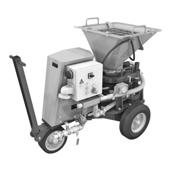
2 Description of unit Operating instructions Aliva-257 Top Components 257.002 Control cabinet • Controls Filling hopper Jouncer Rotor Blow-off chamber Chassis Air unit Solenoid valve • Compressed air supply Version 1.0... - Page 21 Operating instructions Aliva-257 Top 2 Description of unit 257.003 Lube pump • Central lube system Drive unit • Electric motor / frequency converter / gearbox Exhaust Rotor chamber vent • When dry spraying with dust sack Version 1.0...
-
Page 22: Control Displays
2 Description of unit Operating instructions Aliva-257 Top 2.3.1 Control displays 257.004 Level display • Gear oil Name plate Version 1.0... -
Page 23: Operating Parts And Connections
Operating instructions Aliva-257 Top 2 Description of unit Operating parts and connections 2.4.1 Overview 257.005 Socket • Power connection attachment unit plug Socket • Remote control Clamp Manometer • Bottom air pressure manometer Ball valve 1¼“ • Top air Ball valve ¾“ •... -
Page 24: Control Cabinet
2 Description of unit Operating instructions Aliva-257 Top 2.4.2 Control cabinet 257.006 Switch • Main switch ON / OFF Button • EMERGENCY-STOP reset EMERGENCY-STOP • EMERGENCY-STOP Buttons • Green: Start air/rotor button • Red: Stop air/rotor button Version 1.0... -
Page 25: Drive Motor / Frequency Converter
Operating instructions Aliva-257 Top 2 Description of unit 2.4.3 Drive motor / frequency converter 257.031 257.007 Rotary knob • +/- rotor speed Diagram • Flow volume Version 1.0... -
Page 26: Remote Control
2 Description of unit Operating instructions Aliva-257 Top 2.4.4 Remote control Fig. 2.1 Remote control (option) 257.008 EMERGENCY-STOP • EMERGENCY-STOP Control lamp • Remote control plugged in 3, 4 Buttons • Green: Start air/rotor button • Red: Stop air/rotor button Version 1.0... -
Page 27: Operating Modes
Operating instructions Aliva-257 Top 2 Description of unit Operating modes The machine works using the thin-stream process, i.e. it conveys concrete with addition of compressed air. NOTE The machine can be operated in two modes: dry spraying and wet spraying. Decide which mode you want to use before conveying concrete. - Page 28 2 Description of unit Operating instructions Aliva-257 Top Fig. 2.3 The feed range using a hose is limited Feed range horizontally to max. 80 m. max. 80 m The hose diameters are given in the Technical Data (see "5.3 Air 257.010 consumption"...
-
Page 29: Wet Spraying
Operating instructions Aliva-257 Top 2 Description of unit 2.5.2 Wet spraying The Conveyor material is conveyed wet 2 into the filling hopper 3 of the machine. Using compressed air 1 the Conveyor material is conveyed through the conveyor hose 5 to the nozzle 6. The Conveyor material is mixed before the nozzle 6 with compressed air 4 and additive 4. -
Page 30: Mode Of Operation
2 Description of unit Operating instructions Aliva-257 Top Mode of operation The machine works according to the rotor principle. The Conveyor material in the filling Fig. 2.7 Rotor principle hopper 7 slides into the rotor chamber 6. 1 Top air By rotating the rotor 2 and the connected 2 Rotor top air 1 the Conveyor material is... -
Page 31: Startup
Operating instructions Aliva-257 Top 3 Startup Startup This chapter describes the required steps for startup of the machine. Observe the safety instructions (see "1.2 Safety instructions" on page 3). Transport / placement Unload the machine from the lorry using suitable lifting gear. HAZARD Inclines •... -
Page 32: Check The Ball Valves
3 Startup Operating instructions Aliva-257 Top Check the ball valves Before connecting the machine, turn the main switch 1 to “O”. Fig. 3.2 Make sure that the “Top air” 3, “Bottom Close ball valves air” 4, “Compressed air supply” 5, and 1 Main switch the “Jouncer”... -
Page 33: Connect Hoses
Operating instructions Aliva-257 Top 3 Startup Connect hoses 3.3.1 Connect compressed air hose NOTE You need a compressor, because the machine is operated using the thin-stream process. Your sales person can inform you which compressor is required. The max. permissible inlet pressure at the machine is 7 bar. HAZARD Compressed air •... - Page 34 3 Startup Operating instructions Aliva-257 Top If you do not have your own compressed air hose with conical coupling, Fig. 3.4 Undo the screws for the hose clamp Remove hose clamp and and pull off the hose clamp. 257.018 Fig. 3.5 Attach a suitable compressed air hose Attach compressed to the nozzle on the conical coupling.
-
Page 35: Connect Conveyor Hose
Operating instructions Aliva-257 Top 3 Startup 3.3.2 Connect conveyor hose NOTE The diameter and length of the required conveyor hose are listed in diagrams in Chapter "5.3 Air consumption" on page 49. The spraying system must have the same diameter as the conveyor hose. HAZARD Compressed air •... - Page 36 3 Startup Operating instructions Aliva-257 Top Open the coupling on the blow-off chamber and remove the rubber seal. NOTE Stretch the rubber seal by hand to ensure an improved fit later on. Push the rubber seal 1 half onto the Fig.
- Page 37 Operating instructions Aliva-257 Top 3 Startup WARNING Non-secured couplings • If couplings are not secured then the hose can rip when conveying material, thereby causing severe injuries. Always secure the couplings with linchpins to ensure they do not open when conveying material.
- Page 38 3 Startup Operating instructions Aliva-257 Top Fig. 3.11 Place the coupling 1 around the rubber Mount the coupling seal and close the coupling. 1 Coupling 2 Reducer Secure the coupling with linchpin. The reducer 2 is fitted. Now connect the conveyor hose to the reduction cone, "3.3.2 Connect conveyor hose"...
-
Page 39: Clamp Rotor Discs
Operating instructions Aliva-257 Top 3 Startup 3.3.3 Clamp Rotor discs NOTE Follow the instructions on clamping the Rotor discs exactly. Incorrect clamping increases wear. Fig. 3.12 There are two clamp types: A and B. Differences in clamp types 257.026 Fig. 3.13 Screw on all clamps by hand up to the Tighten the clamp stop. -
Page 40: Connect The Power Cable
3 Startup Operating instructions Aliva-257 Top Connect the power cable WARNING Electrical shock • If electrical components are exposed to moisture, there is a risk of electrical shock. Protect all electrical components from moisture. NOTE • Refer to the details in the Control cabinet and in the electrical schematic for the required connection voltage of machine. -
Page 41: Operation
Operating instructions Aliva-257 Top 4 Operation Operation This chapter describes the work steps required to operate, securely and efficiently work with the machine, as well as to stop the conveying and to clean the machine. Observe the safety instructions (see "1.2 Safety instructions" on page 3). HAZARD Improper operation •... -
Page 42: Preparing To Convey
4 Operation Operating instructions Aliva-257 Top Preparing to convey 4.1.1 Function check of rotor machine HAZARD Compressed air • Risk of death from compressed air. Never open a ball valve in an uncontrolled manner. Hold the conveyor hose and nozzle firmly before opening the air supply. NOTE Make sure that air and current are connected and that the clamp is tightened. - Page 43 Close the “Compressed air supply” ball valve 1½“. Set the main switch to OFF. NOTE If there are faults during the function checks then read the "Faults" chapter in the maintenance instructions. If you can not remedy the fault then contact the Sika Service Line. Version 1.0...
-
Page 44: Stop
4 Operation Operating instructions Aliva-257 Top Stop HAZARD Improper operation • Improper operation of the machine will result in the risk of death. You must always convey concrete with a second person present because the machine can not be operated by only one person. NOTE The following action instructions apply to the worker operating the machine. -
Page 45: Adjust Empty Air Resistance
Operating instructions Aliva-257 Top 4 Operation 4.2.2 Adjust empty air resistance HAZARD Improper operation • Improper operation of the machine will result in the risk of death. Hold the conveyor hose at its end and on the nozzle! Otherwise, persons may be seriously injured! Do not point the spray nozzle in the direction of persons. - Page 46 4 Operation Operating instructions Aliva-257 Top Fig. 4.16 Adjust empty air resistance 1 Start air/rotor 2 Main switch 3 EMERGENCY- STOP reset 4 Top air 5 Bottom air 6 Compressed air supply 257.030 Set the main switch 2 to ON. Open the “Compressed air supply”...
- Page 47 Operating instructions Aliva-257 Top 4 Operation Wet spraying Turn the ball valves of the top and bottom air parallel until the conveying air manometer displays approx. 0.6 bar. If the pressure becomes too high or low when conveying concrete at a later time, then regulate it accordingly. The empty air resistance is set for wet spraying.
-
Page 48: Select Rotor Speed
4 Operation Operating instructions Aliva-257 Top 4.2.3 Select rotor speed Fig. 4.17 Select the rotor speed with the rotary 1 Rotary button/ button 1 on the frequency converter. frequency Observe specifications in the converter diagram 2 on the cover. 2 Flow volume diagram The rotor speed is set. -
Page 49: Fill Filling Hopper / Regulate Jouncer
Blow-off chamber with formwork oil, otherwise the wet concrete will stick onto them. You can obtain a spraying unit for the formwork oil from Sika. Always pour the mixture into the middle of the Filling hopper to ensure even filling. -
Page 50: Spray Concrete
4 Operation Operating instructions Aliva-257 Top 4.2.5 Spray concrete 4.2.5.1 Start/stop the supply at the controls on the Control cabinet HAZARD Improper operation • Improper operation of the machine will result in the risk of death. You must always warn your colleagues at the nozzle before opening the compressed air supply to be sure that he/she really is holding the nozzle. - Page 51 Operating instructions Aliva-257 Top 4 Operation 4.2.5.2 Start the supply at the controls on the Remote control (option) HAZARD Improper operation • Improper operation of the machine will result in the risk of death. You must always warn your colleagues at the nozzle before opening the compressed air supply to be sure that he/she really is holding the nozzle.
-
Page 52: Interrupt Conveying
4 Operation Operating instructions Aliva-257 Top Interrupt conveying NOTE Observe the setting time of your concrete when wet spraying It might take less than half an hour for the concrete to harden in case of an interruption. Discuss the time with your concrete supplier. If you want to interrupt the feed for a maximum of 1/2 hour: Worker Press the "Stop air/rotor"... -
Page 53: Stop
Operating instructions Aliva-257 Top 4 Operation Stop How you stop the feed depends on the operating mode. 4.4.1 Dry spraying NOTE During dry spraying, never clean the machine with water. The dry concrete will otherwise harden and block the machine. Because the water only reaches the conveyor hose shortly before the nozzle, there is a danger that the hardening Conveyor material could block the machine. -
Page 54: Wet Spraying
4 Operation Operating instructions Aliva-257 Top Press the "Stop air/rotor" button to stop the conveying air. Compressed air stops flowing through the conveying hose. Turn the main switch to “O”. Close the “Compressed air supply” ball valve 1½“. The machine is now switched off. Worker at Place the nozzle down so that its opening points downwards. - Page 55 Operating instructions Aliva-257 Top 4 Operation If the machine is soiled by Conveyor material, remove it with water. Remove remains using a cloth or wiper. You must use a scraper to remove adhering material. NOTE Remove the grid on the Filling hopper only in case of heavy soiling. After cleaning, re-fit the grid immediately.
- Page 56 4 Operation Operating instructions Aliva-257 Top Version 1.0...
-
Page 57: Technical Data
Operating instructions Aliva-257 Top 5 Technical data Technical data This chapter supplies you with all the technical data you require. We reserve the right to make technical and design changes at any time. The technical data given here correspond to the theoretical values which may be reached under normal conditions. -
Page 58: Dimensional Drawings
5 Technical data Operating instructions Aliva-257 Top Dimensional drawings Fig. 5.20 1580 Rotor 12 l 1320 mm 6.0 l 1185 mm 2.5 l 1100 mm Weight: ~650 kg Version 1.0... -
Page 59: Air Consumption
Operating instructions Aliva-257 Top 5 Technical data Air consumption 5.3.1 Dry spraying 5.3.1.1 Example calculation We provide an example calculation here to show you how to calculate the air requirements. Task 4 m /h dry mixture is to be conveyed 120 m; the selected hose diameter is 50/ 70 mm. - Page 60 5 Technical data Operating instructions Aliva-257 Top 5.3.1.2 Diagrams You can read the air consumption and the hose outlet pressure from the following diagrams; the hoses have rated widths RW (internal diameter) of 32 mm, 38 mm, 50 mm, 60 mm and 68 mm. Fig.
- Page 61 Operating instructions Aliva-257 Top 5 Technical data Fig. 5.4 263.099 Dry diagram, DRY SPRAYING-HOSEØ50 RW 50 Guidelineforairconsumptionandtransportpressure resistance 10,5 11,3 [m3/min.] Fig. 5.5 Dry diagram DRY SPRAYING - HOUSE ø60 263.084_EN RW 60 Rules of thumb for air consumption and outlet pressure /h 7m Empty air Conveying...
- Page 62 5 Technical data Operating instructions Aliva-257 Top Fig. 5.6 Dry-spraying hose ø65 Dry diagram 263.085_EN RW 65 Reference values for air consumption and pump pressure Empty air Conveying dist. Air consumption 11,5 13,8 15,2 16,6 17,7 18,7 [m3/min.] Version 1.0...
-
Page 63: Wet Spraying
Operating instructions Aliva-257 Top 5 Technical data 5.3.2 Wet spraying 5.3.2.1 Example calculation We provide an example calculation here to show you how to calculate the air requirements. Task 7 m /h wet mixture is to be conveyed 35 m; the selected hose diameter is 60/80 mm. - Page 64 5 Technical data Operating instructions Aliva-257 Top 5.3.2.2 Diagrams You can read-off the air consumption and the hose outlet pressure from the following diagrams; the hoses have rated widths RW (internal diameter) of 50 mm, 60 mm and 65 mm. Fig.
- Page 65 Operating instructions Aliva-257 Top 5 Technical data Fig. 5.10 263.105 Wet diagram, WETSPRA YING-HOSEØ65 RW 65 Guidelineforairconsumptionandtransportpressure resistance empty 15,5 18,5 [m3/min. Version 1.0...
-
Page 66: Lube Pump Grease
5 Technical data Operating instructions Aliva-257 Top Lube pump grease Type of drive 24 V / DC Current consumption at 280 bar 3,8 A counterpressure Protection class IP65 Rotary motion of stirrer Clockwise Speed of stirrer 18 rpm Lubrication time Set at factory to 8 seconds Cycle time Set at factory to 1 minute... - Page 67 257.001 Aliva 257 Top Concrete spraying machine 312831 / TWA / 000 / 00 / AA / EN...
- Page 68 Translating of the original operating instructions 312830_TWA_AA...
- Page 69 Maintenance instructions Aliva-257 Top Table of contents Notes ..........1 About this manual .
- Page 70 Maintenance instructions Aliva-257 Top 2.16 Operating materials and lubricant ......41 2.16.1 Gear oil .
-
Page 71: Notes
Maintenance instructions Aliva-257 Top 1 Notes Notes Purpose This manual provides you with all the information you need for safe, efficient work with the machine/unit. Read this chapter carefully; it is important for your safety and that of your coworkers. About this manual Purpose This chapter provides information about the symbols used in this manual. -
Page 72: Work Instructions
1 Notes Maintenance instructions Aliva-257 Top 1.1.2 Work instructions INCLINE Means that death or severe bodily injury MAY occur if the incline of the floor surface is more than 2%. WARNING Warns of possible minor material damage. NOTE Information which simplifies work. 1.1.3 Symbols used This arrow denotes action instructions. -
Page 73: Safety Instructions
Do not remove required covers, such as safety grids, etc. Do not make modifications to the machine. Do not point the spray nozzle in the direction of persons. Use only original replacement parts from Sika Schweiz AG, and install them properly. Risk of explosion •... - Page 74 1 Notes Maintenance instructions Aliva-257 Top WARNING Vibrations • The machine moves in an uncontrolled manner if knocked or subject to vibrations when conveying concrete, and can no longer be controlled due to the heavy weight. Secure the machine's wheels by placing wedges underneath them. •...
- Page 75 Maintenance instructions Aliva-257 Top 1 Notes CAUTION Insufficient light • Injuries can occur when working in insufficient light. Ensure sufficient illumination and safety in the workplace. Insufficient maintenance • Insufficient maintenance can cause injuries and defects. Carry out the specified maintenance tasks regularly. CAUTION CAUTION Poisoning of drinking water!
-
Page 76: Personal Safety Gear
1 Notes Maintenance instructions Aliva-257 Top 1.2.1 Personal safety gear The following lists apply to all people in the danger zone of the machine. Always wear usual construction site safety equipment, such as: Safety helmet Safety boots Safety clothing Safety gloves Since you will be working with cementitious materials and additives, and due to the noise level of the machine, you should also wear: Safety glasses... -
Page 77: Who May Operate This Machine
(e.g. spray- washing a car with water). We, Sika Schweiz AG, bear no liability for any damages resulting from incorrect use that is not in accordance to these instructions. - Page 78 1 Notes Maintenance instructions Aliva-257 Top Version 1.0...
-
Page 79: Maintenance And Repair Work
Improper operation • Danger to life due to incorrect operation. Work with and on the machine may only be carried out by trained personnel. Use only original replacement parts from Sika Schweiz AG, and install them properly. NOTE • Preventive maintenance is cost-effective maintenance! Always carry out the maintenance work according to the schedule! •... -
Page 80: Overview Of Maintenance Schedule
2 Maintenance and repair work Maintenance instructions Aliva-257 Top Overview of maintenance schedule Service tasks Regular maintenance every... 10 h 50 h 200 h 2000 h 1 day 1 week 1 month 1 year Clean machine (see Maintenance instructions) Check EMERGENCY-STOP function (see Maintenance instructions) 2.4.1 Fill the lube pump, see page 11 2.5 Lubricate rotor shaft, see page 15... -
Page 81: Cleaning Hose
Maintenance instructions Aliva-257 Top 2 Maintenance and repair work Cleaning hose The feed line to the jouncer is also used as a cleaning hose for the machine. The hose must be disconnected from the jouncer for cleaning and maintenance work. Fig. - Page 82 2 Maintenance and repair work Maintenance instructions Aliva-257 Top Fig. 2.2 Grease gun Screw the cleaning hose onto at the and cleaning hose bottom of the grip on the grease gun. Carefully open “Jouncer” ball valve. 257.035 NOTE Make sure that no air enters the lube pump when filling! Fig.
-
Page 83: Adjust Lubrication Time
Maintenance instructions Aliva-257 Top 2 Maintenance and repair work 2.4.2 Adjust lubrication time If the rubber seals for the Rotor discs are insufficiently or over-lubricated, then change the lubrication time for the lube pump. NOTE To increase intensity of lubrication, you can extend the lubrication time accordingly. -
Page 84: Vent The Lube Pump
2 Maintenance and repair work Maintenance instructions Aliva-257 Top 2.4.3 Vent the lube pump NOTE If there is air in the pump housing then the wear plates will not longer be supplied with grease. To vent the pump outlet: Fig. 2.5 Close the “Compressed air supply”... -
Page 85: Lubricate Rotor Shaft
Maintenance instructions Aliva-257 Top 2 Maintenance and repair work Lubricate rotor shaft Lubricate the rotor shaft on the lubrication nipple in the area of the motor. Clean the lubrication nipple 1. Fig. 2.6 1 Lubrication Place the grease gun onto the nipple lubrication nipple. -
Page 86: Clean Filling Hopper
2 Maintenance and repair work Maintenance instructions Aliva-257 Top Clean Filling hopper NOTE The Filling hopper is normally cleaned on the completion of the conveying process, see section 4.4 “Stop” in the Maintenance instructions. If there should nevertheless be firmly adhering deposits in the Filling hopper, remove them in accordance with the following instructions. -
Page 87: Clean Rotor Chamber Vent
Maintenance instructions Aliva-257 Top 2 Maintenance and repair work Clean Rotor chamber vent NOTE The inside of the Rotor chamber vent must be cleaned primarily after wet spraying. However, after dry spraying check the inside of the Rotor chamber vent for adhering deposits. - Page 101 Maintenance instructions Aliva-257 Top 2 Maintenance and repair work 2.12.5 Replace Rotor disc Dropping rotor components • There is a risk of injury if rotor components are dropped. Make sure the rotor components do not fall. Remove the rotor, see Chapter "2.12.1 Remove the rotor" on page 24. Place the new flat seal onto the rotor and spray it with a rust protection spray.
-
Page 102: 2.12.6 Changeover Rotor Size
2 Maintenance and repair work Maintenance instructions Aliva-257 Top 2.12.6 Changeover rotor size 2.12.6.1 Replace rotor Rotors with swallowing capacities of 12 l, 6 l, 2.5 ll are available for the Aliva 257. To changeover the size of the rotor: Clean the machine (see Maintenance instructions). - Page 103 Maintenance instructions Aliva-257 Top 2 Maintenance and repair work Fig. 2.24 Place the new rotor on a suitable Replace Rotor discs surface to mount the lower Rotor disc. 1 Upper Rotor disc 2 Upper flat seal Clean the bearing area of the rotor 3 3 Rotor and spray it with rust protection spray.
- Page 104 2 Maintenance and repair work Maintenance instructions Aliva-257 Top 2.12.6.2 Modify clamp The related clamps to suit the rotor used Fig. 2.25 Clamp sizes must be used. Rotor type Clamp length X 12 l 447.5 mm 312.5 mm 2.5 l 227.5 mm 257.056 Remove the rotor, see Chapter "2.12.1 Remove the rotor"...
-
Page 105: 2.12.7 Assemble Rotor
Maintenance instructions Aliva-257 Top 2 Maintenance and repair work 2.12.7 Assemble rotor Rotor installation Fig. 2.27 Apply liberal amounts of grease to the 1 Wear plate wear plate 1. Also apply liberal amounts of grease to the Rotor disc. 257.058 Fig. - Page 106 2 Maintenance and repair work Maintenance instructions Aliva-257 Top Rotor cover plate installation Fig. 2.30 Fit the rotor cover plate 1 with the aid 1 Rotor cover of a mechanical lifting aid. 2 Handles For this purpose attach the crane hooks to the handles 2.
- Page 107 Maintenance instructions Aliva-257 Top 2 Maintenance and repair work Fit Filling hopper Fig. 2.33 Fit Filling Fit the Filling hopper 2 with the aid of a hopper mechanical lifting aid. 1 Handle For this purpose attach the crane 2 Filling hopper hooks to the handles 1.
-
Page 108: Replace Pushbuttons And Lamps
2 Maintenance and repair work Maintenance instructions Aliva-257 Top 2.13 Replace pushbuttons and lamps HAZARD Electrical shock • During work at the control cabinet, there is risk of death due to electric shock. Contract an electrician for the work at the control cabinet. Before commencing work at the control cabinet, completely switch off the machine and pull the electric supply plug. -
Page 109: Blow Out The Electric Motor / Motor Compartment
Maintenance instructions Aliva-257 Top 2 Maintenance and repair work 2.14 Blow out the electric motor / motor compartment Place on the cleaning hose, "2.2 Cleaning hose" on page 11. NOTE • Read and observe the Maintenance instructions. • Make sure that the clamps are tensioned. Lift up the cowl. -
Page 110: Check And Replace Gear Oil
2 Maintenance and repair work Maintenance instructions Aliva-257 Top 2.15 Check and replace gear oil 2.15.1 Check oil level Fig. 2.35 Check the oil level at the oil view Check oil level glass 1. The view window must be 1 Oil view glass filled up to a minimum of 10 mm or to the red marker. -
Page 111: Operating Materials And Lubricant
Maintenance instructions Aliva-257 Top 2 Maintenance and repair work 2.16 Operating materials and lubricant 2.16.1 Gear oil Energrease LS-EP 90 Hypoid gear oil with EP additive (Extreme Pressure) ESSO: Gear-Oil GX 90 Viscosity class acc. to ISO 3448: MOBIL: Mobilube GX 90/HD 90 VG 150-220 SHELL: Spirax HD 90... - Page 112 2 Maintenance and repair work Maintenance instructions Aliva-257 Top Version 1.0...
-
Page 113: Faults
Maintenance instructions Aliva-257 Top 3 Faults Faults If faults continue to occur despite regular maintenance then this chapter describes how to remedy these faults. HAZARD Improper operation • Danger to life due to incorrect operation. Work with and on the machine may only be carried out by trained personnel. HAZARD Compressed air •... -
Page 114: What Happens If
3 Faults Maintenance instructions Aliva-257 Top What happens if ...? Fault Possible causes Remedies Electric motor does not No or insufficient input Check whether the input voltage is start up. voltage. connected to all phases (this check may only be carried out by trained personnel). - Page 115 Maintenance instructions Aliva-257 Top 3 Faults Fault Possible causes Remedies Blockage in rotor, Blow-off Excessive additive. If there is a blockage in the conveyor chamber or conveyor line. line then switch off the rotor. WARNING: Material can escape suddenly! Always secure an open hose end! Release the conveyor line at the Blow-off chamber, open the conveying...
- Page 116 3 Faults Maintenance instructions Aliva-257 Top Fault Possible causes Remedies Reduced power. Rotor chamber or Blow-off Completely clean machine. chamber opening reduced in size by material. Incorrect air setting. Regulate the top and bottom air (For empty air resistance, see Operation manual). Filling hopper is not full.
- Page 117 Maintenance instructions Aliva-257 Top 3 Faults Fault Possible causes Remedies Rebound too high. Unfavourable grading Check and adjust grading curve if curve. necessary. Clearance between spray Increase nozzle distance nozzle and spraying area to 0.8 m - 1.2 m. is too low. Clearance between spray Reduce nozzle distance nozzle and spraying area...
- Page 118 3 Faults Maintenance instructions Aliva-257 Top Fault Possible causes Remedies No air. “Compressed air” ball Open “Compressed air supply” ball valve 1½“ closed. valve 1½“. Solenoid valve closed. Check solenoid valve, replace if necessary. Air does not switch off. Solenoid valve blocked or Close “Compressed air supply”...
-
Page 119: Additional Help
Additional help If you cannot correct your problem despite this explicit description, the Sika Schweiz AG service line is always ready to help. You can find the telephone number in our contact information page. Please always remember to give us the information on the machine name plate so that we can help you efficiently. - Page 120 3 Faults Maintenance instructions Aliva-257 Top Version 1.0...
-
Page 121: Decommissioning
Maintenance instructions Aliva-257 Top 4 Decommissioning Decommissioning Transporting HAZARD Machine can slip and tilt over • There is a risk of death and serious injuries if the machine slips or tilts over during transport. Secure the machine against slippage and tilt. NOTE Always clean the machine before transport. -
Page 122: Storage
4 Decommissioning Maintenance instructions Aliva-257 Top Storage Before storing the machine, you must clean it thoroughly and release the wear plates. Release the three clamps with a flat spanner. Re-tighten the clamps slightly by hand. The wear plates are now released. NOTE Store the machine, •... -
Page 123: Maintenance Log
Maintenance instructions Aliva-257 Top 5 Maintenance log Maintenance log Maintenance log as required NOTE Please copy this list and always fill out the copy. Service work ... Date of the work 2.3 Fill grease gun, see page 11 2.4.2 Adjust lubrication time, see page 13 2.4.3 Vent the lube pump, see page 14 2.12.2 Clean rotor, see page 26 2.12.3 Replace upper wear plate, see page 27... - Page 124 5 Maintenance log Maintenance instructions Aliva-257 Top Version 1.0...
-
Page 125: Maintenance Log After 10 Hrs Or 1 Day
Maintenance instructions Aliva-257 Top 5 Maintenance log Maintenance log after 10 hrs or 1 day NOTE Please copy this list and always fill out the copy. Service work ... Completed Clean machine (see Maintenance instructions) Check EMERGENCY-STOP function (see Maintenance instructions) 2.4.1 Fill the lube pump, see page 11 2.5 Lubricate rotor shaft, see page 15... - Page 126 5 Maintenance log Maintenance instructions Aliva-257 Top Version 1.0...
-
Page 127: Maintenance Log After 200 Hrs Or 1 Month
Maintenance instructions Aliva-257 Top 5 Maintenance log Maintenance log after 200 hrs or 1 month NOTE Please copy this list and always fill out the copy. Service work ... Completed 2.6 Lubricate steering axle, see page 15 2.14 Blow out the electric motor / motor compartment, see page 39 2.15.1 Check oil level, see page 40 We hereby confirm that the maintenance work listed above has been carried out. - Page 128 5 Maintenance log Maintenance instructions Aliva-257 Top Version 1.0...
-
Page 129: Maintenance Log After 2000 Hrs Or 1 Year
Maintenance instructions Aliva-257 Top 5 Maintenance log Maintenance log after 2000 hrs or 1 year NOTE Please copy this list and always fill out the copy. Service work ... Completed 2.15.2 Replace the gear oil, see page 40 We hereby confirm that the maintenance work listed above has been carried out. Location: . - Page 130 5 Maintenance log Maintenance instructions Aliva-257 Top Version 1.0...
- Page 131 257.001 Aliva 257 Top Concrete spraying machine 312831 / TEK / 000 / 01 / AB / EN...
- Page 133 Contents AL257 Top 2.5L plates steel/steel chassis MAT-Nr. 312515 ..........1 AL257 Top 2.5L plates rubber/steel chassis MAT-Nr.
- Page 134 Air hose D32/48 L700 A1 1/4“-KKRD46 MAT-Nr. 312689 ..........43 Rotor cover plate cpl.
- Page 135 Lubrication plate cpl. grease MAT-Nr. 312746 ..........89 Grease gun cpl.
-
Page 136: Al257 Top 2.5L Plates Steel/Steel Chassis
AL257 Top 2.5L plates steel/steel chassis Spare parts list MAT-Nr. 312515 Aliva 257 Top Version 2.0... - Page 137 Spare parts list Aliva 257 Top Designation: AL257 Top 2.5L plates ste/ste chassis Material-Nr.: 312515 Item Mat-Nr. Unit Denomination 312516 Basic element cpl 312510 El Drive cpl 400V 312230 Chassis 319035 Rotor 2.5L cpl N1 257 312352 Hood Basic el 257...
-
Page 138: Al257 Top 2.5L Plates Rubber/Steel Chassis
AL257 Top 2.5L plates rubber/steel chassis Spare parts list MAT-Nr. 318720 Aliva 257 Top Version 2.0... - Page 139 Spare parts list Aliva 257 Top Designation: AL257 Top 2,5L plates ru/ste chassis Material-Nr.: 318720 Item Mat-Nr. Unit Denomination 312516 Basic element cpl 312510 El Drive cpl 400V 312230 Chassis 319035 Rotor 2.5L cpl N1 257 312352 Hood Basic el 257...
-
Page 140: Al257 Top 2.5L Plates Steel/Steel Skid
AL257 Top 2.5L plates steel/steel skid Spare parts list MAT-Nr. 314652 Aliva 257 Top Version 2.0... - Page 141 Spare parts list Aliva 257 Top Designation: AL257 Top 2.5L plates ste/ste skid Material-Nr.: 314652 Item Mat-Nr. Unit Denomination 312516 Basic element cpl 312510 El Drive cpl 400V 314653 Skid 319035 Rotor 2.5L cpl N1 257 312352 Hood Basic el 257...
-
Page 142: Al257 Top 2.5L Plates Rubber/Steel Skid
AL257 Top 2.5L plates rubber/steel skid Spare parts list MAT-Nr. 319419 Aliva 257 Top Version 2.0... - Page 143 Spare parts list Aliva 257 Top Designation: AL257 Top 2.5L plates rubber/steel skid Material-Nr.: 319419 Item Mat-Nr. Unit Denomination 312516 Basic element cpl 312510 El Drive cpl 400V 314653 Skid 319035 Rotor 2.5L cpl N1 257 312352 Hood Basic el 257...
-
Page 144: Al257 Top 6L Plates Steel/Steel Chassis
AL257 Top 6L plates steel/steel chassis Spare parts list MAT-Nr. 312660 Aliva 257 Top Version 2.0... - Page 145 Spare parts list Aliva 257 Top Designation: AL257 Top 6L plates ste/ste chassis Material-Nr.: 312660 Item Mat-Nr. Unit Denomination 312516 Basic element cpl 312510 El Drive cpl 400V 312230 Chassis 317527 Rotor 6L cpl N1 257 312352 Hood Basic el 257...
-
Page 146: Al257 Top 6L Plates Rubber/Steel Chassis
AL257 Top 6L plates rubber/steel chassis Spare parts list MAT-Nr. 315380 Aliva 257 Top Version 2.0... - Page 147 Spare parts list Aliva 257 Top Designation: AL257 Top 6L plates ru/ste chassis Material-Nr.: 315380 Item Mat-Nr. Unit Denomination 312516 Basic element cpl 312510 El Drive cpl 400V 312230 Chassis 317527 Rotor 6L cpl N1 257 312352 Hood Basic el 257...
-
Page 148: Al257 Top 6L Plates Steel/Steel Skid
AL257 Top 6L plates steel/steel skid Spare parts list MAT-Nr. 314651 Aliva 257 Top Version 2.0... - Page 149 Spare parts list Aliva 257 Top Designation: AL257 Top 6L plates ste/ste skid Material-Nr.: 314651 Item Mat-Nr. Unit Denomination 312516 Basic element cpl 312510 El Drive cpl 400V 314653 Skid 317527 Rotor 6L cpl N1 257 312352 Hood Basic el 257...
-
Page 150: Al257 Top 6L Plates Rubber/Steel Skid
AL257 Top 6L plates rubber/steel skid Spare parts list MAT-Nr. 318533 Aliva 257 Top Version 2.0... - Page 151 Spare parts list Aliva 257 Top Designation: AL257 Top 6L plates ru/ste skid Material-Nr.: 318533 Item Mat-Nr. Unit Denomination 312516 Basic element cpl 312510 El Drive cpl 400V 314653 Skid 317527 Rotor 6L cpl N1 257 312352 Hood Basic el 257...
-
Page 152: Al257 Top 12L Plates Steel/Steel Chassis
AL257 Top 12L plates steel/steel chassis Spare parts list MAT-Nr. 312661 Aliva 257 Top Version 2.0... - Page 153 Spare parts list Aliva 257 Top Designation: AL257 Top 12L plates ste/ste chassis Material-Nr.: 312661 Item Mat-Nr. Unit Denomination 312516 Basic element cpl 312510 El Drive cpl 400V 312230 Chassis 317526 Rotor 12L cpl N1 257 312352 Hood Basic el 257...
-
Page 154: Al257 Top 12L Plates Rubber/Steel Chassis
AL257 Top 12L plates rubber/steel chassis Spare parts list MAT-Nr. 315362 Aliva 257 Top Version 2.0... - Page 155 Spare parts list Aliva 257 Top Designation: AL257 Top 12L plates ru/ste chassis Material-Nr.: 315362 Item Mat-Nr. Unit Denomination 312516 Basic element cpl 312510 El Drive cpl 400V 312230 Chassis 317526 Rotor 12L cpl N1 257 312352 Hood Basic el 257...
-
Page 156: Al257 Top 12L Plates Steel/Steel Skid
AL257 Top 12L plates steel/steel skid Spare parts list MAT-Nr. 314650 Aliva 257 Top Version 2.0... - Page 157 Spare parts list Aliva 257 Top Designation: AL257 Top 12L plates steel/steel skid Material-Nr.: 314650 Item Mat-Nr. Unit Denomination 312516 Basic element cpl 312510 El Drive cpl 400V 314653 Skid 317526 Rotor 12L cpl N1 257 312352 Hood Basic el 257...
-
Page 158: Al257 Top 12L Plates Rubber/Steel Skid
AL257 Top 12L plates rubber/steel skid Spare parts list MAT-Nr. 319417 Aliva 257 Top Version 2.0... - Page 159 Spare parts list Aliva 257 Top Designation: AL257 Top 12L plates rubber/steel skid Material-Nr.: 319417 Item Mat-Nr. Unit Denomination 312516 Basic element cpl 312510 El Drive cpl 400V 314653 Skid 317526 Rotor 12L cpl N1 257 312352 Hood Basic el 257...
-
Page 160: Basic Element Cpl
Basic element cpl. Spare parts list MAT-Nr. 312516 Aliva 257 Top Version 2.0... - Page 161 Spare parts list Aliva 257 Top Designation: Basic element cpl Material-Nr.: 312516 Item Mat-Nr. Unit Denomination 312057 Gearbox Basic el 257 312520 Connec flange cpl Basic el 257 312353 Connect plate cpl Basic el 257 312386 Air distribu Basic el 257...
-
Page 162: Gearbox Cpl
Gearbox cpl. Spare parts list MAT-Nr. 312057 Aliva 257 Top Version 2.0... - Page 163 Spare parts list Aliva 257 Top Designation: Gearbox Basic el 257 Material-Nr.: 312057 Item Mat-Nr. Unit Denomination 171346 Gearbox hous Gearbox 257 146705 Sealing for gear 704×380×0.5mm 312059 Rotor basepla cpl Gear box 257 144357 Grooved ball bearing 67090 Grooved ball bearing 6208...
-
Page 164: Gear Shaft 1 Z15 Cpl
Gear shaft 1 Z15 cpl. Spare parts list MAT-Nr. 313756 Aliva 257 Top Version 2.0... - Page 165 Spare parts list Aliva 257 Top Designation: Gear shaft 1 Z15 cpl Gear box 257 Material-Nr.: 313756 Item Mat-Nr. Unit Denomination Gear shaft 1 Z15 M3 Gearbox 173607 Feather key 8/7×14 BN870 Version 2.0...
-
Page 166: Gear Shaft 2 Z18 Cpl
Gear shaft 2 Z18 cpl. Spare parts list MAT-Nr. 313755 Aliva 257 Top Version 2.0... - Page 167 Spare parts list Aliva 257 Top Designation: Gear shaft 2 Z18 cpl Gear box 257 Material-Nr.: 313755 Item Mat-Nr. Unit Denomination Gear shaft 2 Z18 M4 Gearbox 173609 Feather key 14/9x25 BN870 Version 2.0...
-
Page 168: Rotor Shaft Universal Cpl
Rotor shaft universal cpl. Spare parts list MAT-Nr. 317146 Aliva 257 Top Version 2.0... - Page 169 Spare parts list Aliva 257 Top Designation: Rotor shaft universal cpl gearbox 257 Material-Nr.: 317146 Item Mat-Nr. Unit Denomination Rotor shaft universal cpl gearbox 257 146201 Feather key 14/9×32 BN870 roundst. Version 2.0...
-
Page 170: Dust Cover Cpl
Dust cover cpl. Spare parts list MAT-Nr. 171400 Aliva 257 Top Version 2.0... - Page 171 Spare parts list Aliva 257 Top Designation: Dust cover Gearbox Material-Nr.: 171400 Item Mat-Nr. Unit Denomination 171348 Dust cover Gearbox 66857 Sealing Novapress basic 115×80.1×0.5mm 184077 Bearing cap 3 steel Du cover 257 66785 Shaft sealing ring 40x56x8 66760 O-ring 39.69x3.53mm NBR 70 144080 Grease nipple G1/8"...
-
Page 172: Connecting Flange Cpl
Connecting flange cpl. Spare parts list MAT-Nr. 312520 Aliva 257 Top Version 2.0... - Page 173 Spare parts list Aliva 257 Top Designation: Connec flange cpl Basic el 257 Material-Nr.: 312520 Item Mat-Nr. Unit Denomination 312511 Inter flange In flang 257 173046 O-ring 115x18x6x3 66662 Locking washer rip-lock M12 BN13292 67293 Locking washer rip-lock M16 BN13292 145683 Hex.
-
Page 174: Connecting Plate Cpl
Connecting plate cpl. Spare parts list MAT-Nr. 312353 Aliva 257 Top Version 2.0... - Page 175 Spare parts list Aliva 257 Top Designation: Connect plate cpl Basic el 257 Material-Nr.: 312353 Item Mat-Nr. Unit Denomination 312319 Found board Co plate 257 312334 Angle Co plate 257 66662 Locking washer rip-lock M12 BN13292 145961 Disc M12/24x2.5 zincked BN715 145682 Hex.
-
Page 176: Air Distributor Cpl
Air distributor cpl. Spare parts list MAT-Nr. 312386 Aliva 257 Top Version 2.0... - Page 177 Spare parts list Aliva 257 Top Designation: Air distribu Basic el 257 Material-Nr.: 312386 Item Mat-Nr. Unit Denomination 312411 Air armature welded air arma 257 143268 Solenoid valve L182B48-ZA30A 1 1/2" 24VD 143699 GF92 angle 11/2" zincked 301488 GF530 pipe nipple 11/2- 40 zincked 146733 Ball valve 11/2"...
-
Page 178: Air Hose D32/48 L700 A1 1/4"-Kkrd46
Air hose D32/48 L700 A1 1/4“-KKRD46 Spare parts list MAT-Nr. 312689 Aliva 257 Top Version 2.0... - Page 179 Spare parts list Aliva 257 Top Designation: Air hose D32/48 L700 A1 1/4"- KKRD46 Material-Nr.: 312689 Item Mat-Nr. Unit Denomination 67054 Cone coupling 14/32-Rd46x1/6 with collar 67053 Hose clamp D42-45 145443 0.62 Air hose D32/48 138941 External thread spout D32 11/4"...
-
Page 180: Rotor Cover Plate Cpl
Rotor cover plate cpl. Spare parts list MAT-Nr. 312379 Aliva 257 Top Version 2.0... -
Page 181: Sealing Exhaust
Spare parts list Aliva 257 Top Designation: Ro co plate Basic el 257 Material-Nr.: 312379 Item Mat-Nr. Unit Denomination 312401 Ro co plate formed Ro co pl 257 312409 Centring dev Ro co pl 257 164080 Sealing Exhaust Ro co pl DUO... -
Page 182: Mat-Nr. 164080
Sealing exhaust Spare parts list MAT-Nr. 164080 Aliva 257 Top Version 2.0... - Page 183 Spare parts list Aliva 257 Top Designation: Sealing Exhaust Ro co pl DUO Material-Nr.: 164080 Item Mat-Nr. Unit Denomination 164079 Bushing wear Exhaust 66627 O-Ring 75.57×5.34mm NBR70 Version 2.0...
-
Page 184: Exhaust Cpl
Exhaust cpl. Spare parts list MAT-Nr. 312436 Aliva 257 Top Version 2.0... - Page 185 Spare parts list Aliva 257 Top Designation: Exhaust Ro co pl 257 Material-Nr.: 312436 Item Mat-Nr. Unit Denomination 312434 Exhaust welded Exhaust 312435 Coating Exhaust 312437 Flap in front Exhaust 146160 Elevator screw M6×15 66998 Elevator screw M6×20 136112 Safety nut M6 Kl.6 zincked...
-
Page 186: Hopper Cpl
Hopper cpl. Spare parts list MAT-Nr. 312527 Aliva 257 Top Version 2.0... - Page 187 Spare parts list Aliva 257 Top Designation: Hopper Basic el 257 Material-Nr.: 312527 Item Mat-Nr. Unit Denomination 179286 Hopper device cpl Hopper 312449 Bleeding Bleed 312549 Air vibrating cpl Hopper 312695 Hex. screw to fin M12X25 BN9727 312694 Hex. screw to fin M12X20 BN9727...
-
Page 188: Air Vibrating Cpl
Air vibrating cpl. Spare parts list MAT-Nr. 312549 Aliva 257 Top Version 2.0... -
Page 189: Air Hose D10/17 L1800 A3/8"-I3/8
Spare parts list Aliva 257 Top Designation: Air vibrating cpl Hopper Material-Nr.: 312549 Item Mat-Nr. Unit Denomination 312824 Compressed air ball vibrator NCB 50 143696 GF 92 angle 3/8" zincked 75278 Hose nipple d 10 AG3/8" SW22 144061 Double nipple 3/8×3/8 312547 Air hose D10/17 L1800 A3/8"- I3/8"... -
Page 190: Mat-Nr. 312547
Air hose D10/17 L1800 A3/8“-I3/8“ Spare parts list MAT-Nr. 312547 Aliva 257 Top Version 2.0... - Page 191 Spare parts list Aliva 257 Top Designation: Air hose D10/17 L1800 A3/8"- I3/8" Material-Nr.: 312547 Item Mat-Nr. Unit Denomination 145442 0.67 Autogenous welding hose d10/17mm 74499 Screwed hose connection 3/8"IG 142881 Hose clamp 15-18 Ötiker 75278 Hose nipple d 10 AG3/8" SW22...
-
Page 192: Air Outlet Chamber Cpl
Air outlet chamber cpl. Spare parts list MAT-Nr. 171469 Aliva 257 Top Version 2.0... - Page 193 Spare parts list Aliva 257 Top Designation: Air out cham Basic el 257 Material-Nr.: 171469 Item Mat-Nr. Unit Denomination 174567 Air out chamb DN60 Air out 173890 Seal out cham 257 143668 GF1A elbow 11/4" zincked 312564 Air hose D32/48 L600 A1 1/4" KKRD46...
-
Page 194: Air Hose D32/48 L520 A1 1/4" Kkrd46
Air hose D32/48 L520 A1 1/4“ KKRD46 Spare parts list MAT-Nr. 312564 Aliva 257 Top Version 2.0... - Page 195 Spare parts list Aliva 257 Top Designation: Air hose D32/48 L520 A1 1/4" KKRD46 Material-Nr.: 312564 Item Mat-Nr. Unit Denomination 145443 0.52 Air hose D32/48 67054 Cone coupling 14/32x46 with collar 67053 Hose clamp D42-45 138941 External thread spout D32 11/4"...
-
Page 196: Electric Drive Cpl. 400V Top
Electric drive cpl. 400V Top Spare parts list MAT-Nr. 312510 Aliva 257 Top Version 2.0... - Page 197 Spare parts list Aliva 257 Top Designation: El Drive cpl 400V Material-Nr.: 312510 Item Mat-Nr. Unit Denomination 313944 Electr motor FC 400V N1 drive 66662 Locking washer rip-lock M12 BN13292 145683 Hex. Screw M12×25 8.8 zinked 145989 Locking ring Ø16 schw. DIN471 66863 Seal L6560 green 250x180x0.5mm...
-
Page 198: Electric Motor Fu 400V N1
Electric motor FU 400V N1 Spare parts list MAT-Nr. 313944 Aliva 257 Top Version 2.0... - Page 199 Spare parts list Aliva 257 Top Designation: Electr motor FC 400V N1 drive Material-Nr.: 313944 Item Mat-Nr. Unit Denomination 312497 Frequ changer progr 400V Drive 313943 Electr motor 3kW N1 E-Motor 157330 Speed control knob B31/32 B30 312666 Program FC 3kW FreqConv 257 Version 2.0...
-
Page 200: Chassis Cpl
Chassis cpl. Spare parts list MAT-Nr. 312230 Aliva 257 Top Version 2.0... - Page 201 Spare parts list Aliva 257 Top Designation: Chassis Material-Nr.: 312230 Item Mat-Nr. Unit Denomination 67062 Wheel axle M24 with nuts M12 312242 Wheel support in front Chassis 312412 Bolt Chassis 172525 Solid rubber wheel D=400x105 146022 Cotter pin Ø5×45 ISO1234 BN912 zincked...
-
Page 202: Skid Cpl
Skid cpl. Spare parts list MAT-Nr. 314653 Aliva 257 Top Version 2.0... - Page 203 Spare parts list Aliva 257 Top Designation: Skid Material-Nr.: 314653 Item Mat-Nr. Unit Denomination 312586 Skid welded skid 145973 Disc M24 BN715 zn bl. 145758 Hexagonal screw M24× 8.8 zincked blue 66662 Locking washer rip-lock M12 BN13292 66658 Hexagonal screw M12× 30 8.8 zn.bl.
-
Page 204: Rotor 2.5L Cpl. N1
Rotor 2.5L cpl. N1 Spare parts list MAT-Nr. 319035 Aliva 257 Top Version 2.0... - Page 205 Spare parts list Aliva 257 Top Designation: Rotor 2.5L cpl N1 257 Material-Nr.: 319035 Item Mat-Nr. Unit Denomination 172649 Rotor 2.5L Rotor 317046 Tension spindle 2.5L universal 257 317085 Cone nut M24 cpl universal 257 312726 RoCover cpl.2.5l rotor Version 2.0...
-
Page 206: Rotor 2.5 L With Pin
Rotor 2.5 L with pin Spare parts list MAT-Nr. 172649 Aliva 257 Top Version 2.0... - Page 207 Spare parts list Aliva 257 Top Designation: Rotor 2.5L Rotor Material-Nr.: 172649 Item Mat-Nr. Unit Denomination Rotor 2.5 L worded on Rotor 312588 Actuator Rot 2.5L 25 Version 2.0...
-
Page 208: Rotor Cover Cpl. 2.5L
Rotor cover cpl. 2.5L Spare parts list MAT-Nr. 312726 Aliva 257 Top Version 2.0... - Page 209 Spare parts list Aliva 257 Top Designation: RoCover cpl.2.5l rotor Material-Nr.: 312726 Item Mat-Nr. Unit Denomination 312725 Protecsheet 2.5L SBG RoCover 317594 1.02 Flange protection profile KSD-3 561.3259 Version 2.0...
-
Page 210: Rotor 6L Cpl
Rotor 6L cpl. Spare parts list MAT-Nr. 317527 Aliva 257 Top Version 2.0... - Page 211 Spare parts list Aliva 257 Top Designation: Rotor 6L cpl N1 257 Material-Nr.: 317527 Item Mat-Nr. Unit Denomination 171397 Rotor 6L Rotor 317045 Tension spindle 6L universal 257 312720 RoCover cpl.6L Rotor 317085 Cone nut M24 cpl universal 257 171402...
-
Page 212: Rotor 6L Aluminium With Pin
Rotor 6L aluminium with pin Spare parts list MAT-Nr. 171397 Aliva 257 Top Version 2.0... - Page 213 Spare parts list Aliva 257 Top Designation: Rotor 6L Rotor Material-Nr.: 171397 Item Mat-Nr. Unit Denomination Rotor 6L cpl worded Rotor 163178 Threaded insert M8 type Ensat 302 163320 Guide pinion D12/M8 Rotor Version 2.0...
-
Page 214: Rotor Cover Cpl. 6L
Rotor cover cpl. 6L Spare parts list MAT-Nr. 312720 Aliva 257 Top Version 2.0... - Page 215 Spare parts list Aliva 257 Top Designation: RoCover cpl.6L Rotor Material-Nr.: 312720 Item Mat-Nr. Unit Denomination 312708 Protection 6L SBG RoCover 312598 0.91 Sealing clamping profile EPDM 0.5-2 317594 1.02 Flange protection profile KSD-3 561.3259 Version 2.0...
-
Page 216: Rotor 12L Cpl. N1
Rotor 12L cpl. N1 Spare parts list MAT-Nr. 317526 Aliva 257 Top Version 2.0... - Page 217 Spare parts list Aliva 257 Top Designation: Rotor 12L cpl N1 257 Material-Nr.: 317526 Item Mat-Nr. Unit Denomination 172654 Rotor 12L Alu w pin Rotor 317047 Tension spindle 12L universal 257 312723 RoCover kpl 12L Rotor 317085 Cone nut M24 cpl universal 257...
-
Page 218: Rotor 12 L Aluminium With Pin
Rotor 12 L aluminium with pin Spare parts list MAT-Nr. 172654 Aliva 257 Top Version 2.0... - Page 219 Spare parts list Aliva 257 Top Designation: Rotor 12L Alu w pin Rotor Material-Nr.: 172654 Item Mat-Nr. Unit Denomination Rotor 12L formed Rotor 163178 Threaded insert M8 type Ensat 302 163320 Guide pinion D12/M8 Rotor Version 2.0...
-
Page 220: Rotor Cover Cpl. 12L
Rotor cover cpl. 12L Spare parts list MAT-Nr. 312723 Aliva 257 Top Version 2.0... - Page 221 Spare parts list Aliva 257 Top Designation: RoCover kpl 12L Rotor Material-Nr.: 312723 Item Mat-Nr. Unit Denomination 312722 Protection 12L SBG RoCover 312598 0.91 Sealing clamping profile EPDM 0.5-2 317594 1.02 Flange protection profile KSD-3 561.3259 Version 2.0...
-
Page 222: Control Cabinet Cpl. Top
Control cabinet cpl. Top Spare parts list MAT-Nr. 312696 Aliva 257 Top Version 2.0... - Page 223 Spare parts list Aliva 257 Top Designation: Contr cabinet cpl Material-Nr.: 312696 Item Mat-Nr. Unit Denomination 312097 Control cabinet 300x300x150 312098 CEE plug 5-pole 16A 619/IP67 312099 CEE coupling socket 5-pole 16A 319/IP67 180249 Main switch P1-32/EA/SVB 160293 Push button illuminated green...
-
Page 224: Lubrication Plate Cpl. Grease
Lubrication plate cpl. grease Spare parts list MAT-Nr. 312746 Aliva 257 Top Version 2.0... - Page 225 Spare parts list Aliva 257 Top Designation: Lubrica plate cpl grease Material-Nr.: 312746 Item Mat-Nr. Unit Denomination 144546 Grease pump elect. PICO 104466 Pumping element to pump Pico 144080 Grease nipple G1/8" straight 06.012 144166 Grease nipple 1/4"-H2, 45° 66661...
-
Page 226: Grease Gun Cpl
Grease gun cpl. Spare parts list MAT-Nr. 312175 Aliva 257 Top Version 2.0... - Page 227 Spare parts list Aliva 257 Top Designation: Grease gun Plate lu 237 Material-Nr.: 312175 Item Mat-Nr. Unit Denomination 145233 Grease gun pneumatic BDC 74500 Double nipple 1/4" x 3/8" ot/ot steel 132101 Grease patrone 400gr. pnr.52007 Version 2.0...
-
Page 228: Wear Set Plate Steel/Steel
Wear set plate steel/steel Spare parts list MAT-Nr. 317523 Aliva 257 Top Version 2.0... - Page 229 Spare parts list Aliva 257 Top Designation: Wear set plate steel/steel 257 Material-Nr.: 317523 Item Mat-Nr. Unit Denomination 317513 Part set wearing plate down 257 171395 Wearing plate down Rotor 67293 Locking washer rip-lock M16 BN13292 145710 Hexagonal screw M16×35 8.8 zn.bl.
-
Page 230: Wear Set Plate Rubber/Steel
Wear set plate rubber/steel Spare parts list MAT-Nr. 317165 Aliva 257 Top Version 2.0... - Page 231 Spare parts list Aliva 257 Top Designation: Wear set plate rubber/steel 257 Material-Nr.: 317165 Item Mat-Nr. Unit Denomination 314862 Part set sealing plate lower 257 316513 Gasket plate lower 30mm 67293 Locking washer rip-lock M16 BN13292 145708 Hex screw M16x20 cl.8.8 zincked blue 145827 Cyl.
-
Page 232: Filter Tube With Strap
Filter tube with strap Spare parts list MAT-Nr. 315793 Aliva 257 Top Version 2.0... - Page 233 Spare parts list Aliva 257 Top Designation: Filter tube with strap Material-Nr.: 315793 Item Mat-Nr. Unit Denomination 66889 Filter tube 67035 Strap hy-gear 54 67-114mm Version 2.0...
-
Page 234: Turning Moment Key Sw 46 Cpl
Turning moment key SW 46 cpl. Spare parts list MAT-Nr. 73293 Aliva 257 Top Version 2.0... - Page 235 Spare parts list Aliva 257 Top Designation: Turning moment key SW46 cpl Material-Nr.: 73293 Item Mat-Nr. Unit Denomination 142795 Turning moment key 10-50NM 318509 Transition piece 1/2" - 3/8" 318508 Ring spanner SW46 Version 2.0...
-
Page 236: Remote Control Cpl. 24V (Led)
Remote control cpl. 24V (LED) Spare parts list MAT-Nr. 66848 Aliva 257 Top Version 2.0... - Page 237 Spare parts list Aliva 257 Top Designation: Remote control cpl. 24V (LED) Material-Nr.: 66848 Item Mat-Nr. Unit Denomination 138680 Carrying strap cpl. 143075 Cable 7×1.00mm² pur-pur 156069 Pendant switch compl. 117004 Plug male 7 P, encoded Version 2.0...
-
Page 238: Cable Reel 7P 24Vdc
Cable reel 7P 24VDC Spare parts list MAT-Nr. 91239 Aliva 257 Top Version 2.0... - Page 239 Spare parts list Aliva 257 Top Art. Nr. 91239 Part No. 91239 Ersatzteil / Spare part Ersatzteil / Spare part Part No. 117004 Part No. 94917 Stecker 7P Steckdose 7P Plug 7P Socket 7P Version 2.0...
-
Page 240: Cable Winch Al257
Cable winch AL257 Spare parts list MAT-Nr. 318879 Aliva 257 Top Version 2.0... - Page 241 Spare parts list Aliva 257 Top Designation: Cable winch AL257 Material-Nr.: 318879 Item Mat-Nr. Unit Denomination 318870 Crane support 318875 Column cpl 319354 Bracket cpl. 317978 Hand cable winch TWZ-800 317977 Winding cable D=4mm 319351 Disc bodywork Ø13/45×2.5 galvanized 146591 Disc M10/10.5/30/2.5...
- Page 243 SEMIX AG Sika Schweiz AG / Aliva Equipment Tffenwies 16 CH-8048 Zrich/Switzerland Phone +41 58 436 40 40 +41 58 436 41 40 PROJECT-NO. 2601.02.15 aliva_equipment@ch.sika.com ART. NO. 312696 www.sika.com BUILDING YEAR 8.2008 COMMISSION 2601.02.15 EQUIPMENT SIKA ALIVA AL-257 TOP...
- Page 244 ELECTRICAL DOCUMENTATION : -------------------------- ORDER OF : SIKA SCHWEIZ AG ZšRICH/Switzerland TECHNICAL DOCUMENTATION : ------------------------- FRONT PAGE PANEL LAYOUT CIRCUIT DIAGRAM CABLE LIST PARTS LIST ELECTRICAL DATE : WIRE-COLOURS : WIRE-SIZE : ----------------- ---------------- ----------- POWER SUPPLY 50/60 Hz, 3L+PE black,yellow/green 2.5 mm2...
- Page 245 EXPLANATIONS: ------------ CROSS-REFERENCE: CODE LETTERS: ---------------- ------------- PATH: JUST LOOK AT THE TOP OF THIS SHEET: (0 -9) TEST TEST CAPACITORS /3.2 3.0/ VARIOUS PROTECTIVE DEVICES THE TEXT OR NUMBER JUST AFTER THE ARROW DEFINES THE POTENTIAL AND IS JUST A "NAME" GIVEN BY THE DRAUGHTSMAN. GENERATORS, POWER SUPPLY UNITS THE NUMBER AFTER THE SLASH (/) TELLS YOU ON WHICH PAGE AND PATH TO FIND THE CROSS-REFERENCE.
- Page 246 300x300x150mm (BxHxT) -102S1 ROTOR -155S2 -200S4 -155H2 -200H3 -200S5 -155S1 Datum Datum 19.Jul.2010 19.Jul.2010 LAYOUT LAYOUT 312696_000_02 312696_000_02 Bearb. Bearb. G.MEYER G.MEYER CONTROL PANEL CONTROL PANEL Gepr. Gepr. 08.Aug.2013 08.Aug.2013 2601.02.15 2601.02.15 Urspr. Urspr. Ers.f. Ers.f. Ers.d. Ers.d. Žnderung Žnderung Datum Datum Name...
- Page 247 EASY -200A1 TERMINALS CABLE GLANDS MOUNTED ON BOTTOM 1 x M25(8-11mm) 1 x M20(6-8mm) 2 x M16(6-8mm) Datum Datum 19.Jul.2010 19.Jul.2010 LAYOUT LAYOUT 312696_000_02 312696_000_02 Bearb. Bearb. G.MEYER G.MEYER CONTROL PANEL CONTROL PANEL Gepr. Gepr. 08.Aug.2013 08.Aug.2013 2601.02.15 2601.02.15 Urspr. Urspr.
- Page 249 -101S1 HAUPT- SCHALTER MAIN- SWITCH /102.0 SPEISUNG NETZ POWER SUPPLY MAINS 3L+PE, 3 kW FUSE 16A LEGEND: THE EARTH OF THE SUPPLY CABLE HAVE TO BE GROUNDED = Nominal Current/Nennstrom = Therm. Overload Current/Therm. šberlaststrom Irm = Short circuit Current/Kurzschlussstrom Datum Datum POWER SUPPLY MAINS...
- Page 250 -102F1 C16A -155G1 155.1 E-STOP Q3:1 -200A1 200.1 Q3:2 101.3/ -X10 CABLE 1 CABLE 2 4x2.5mm2 3x0.5mm2 -PTC -102U1 R+ R- FI VARMECA 32T 400 START NOTSTOP EMERGENCY STOP -102M1 ROTOR AL-257 3 x400V 3 kW ROTOR AL-237 3 x400V 2.2 kW Datum Datum ROTOR AL-247...
- Page 251 24VDC /155.0 -151F1 C10A -155G1 155.1 400V -151G1 24VDC 24VDC+E /170.0 0VDC /155.0 Datum Datum POWER SUPPLY 24VDC POWER SUPPLY 24VDC 312696_000_02 312696_000_02 Bearb. Bearb. G.MEYER G.MEYER Gepr. Gepr. 08.Aug.2013 08.Aug.2013 2601.02.15 2601.02.15 Urspr. Urspr. Ers.f. Ers.f. Ers.d. Ers.d. Žnderung Žnderung Datum Datum...
- Page 252 24VDC 24VDC 151.9/ /180.0 E-STOP.2 /180.1 -155S1 -155S2 -155H2 -155G1 SICHERHEITSMODUL SAFETY MODULE 24V,DC -155H2 -155S2 0VDC 0VDC 151.9/ /170.0 NOT-STOP NOT-HALT RESET EMERGENCY-STOP EMERGENCY-STOP RESET 102.7 151.7 Datum Datum EMERGENCY STOP EMERGENCY STOP 312696_000_02 312696_000_02 Bearb. Bearb. G.MEYER G.MEYER Gepr.
- Page 253 24VDC+E 24VDC+E 151.8/ /180.0 Q4:1 Q5:1 -200A1 -200A1 200.1 200.1 Q4:2 Q5:2 AUTO ON 0VDC 0VDC 155.9/ /180.0 -X10 -170V6 CABLE 3 2x1mm2 CABLE 4 2x1mm2 -170A1 -170Y6 TIMER ON 2..59sec TIMER OFF 1..16Min SCHMIERUNG LUFTVENTIL AUTO AIR VALVE LUBRICATION AUTO Datum Datum...
- Page 254 -180S1 -180S3 -180S5 -180H6 CABLE 9 8x1mm2 -X20 Q1:1 -200A1 START STOP REMOTE /200.6 /200.7 /200.3 200.1 Q1:2 E-STOP.2 155.9/ 24VDC 24VDC 155.9/ /200.0 24VDC+E 24VDC+E 170.9/ /200.2 0VDC 0VDC 170.9/ /200.0 NOTSTOP START SPRITZEN STOP SPRITZEN SPRITZEN FERN EMERGENCY STOP START SPRAYING STOP SPRAYING AKTIV...
- Page 255 24VDC 180.9/ OPTION: BEI VERWENDUNG MIT AL-571 ODER AL-572 I12 MIT 24VDC VERBINDEN IF USED WITH AL-571 OR AL-572 CONNECT I12 TO 24VDC -200S5 -200S4 -200H3 START STOP 180.3/ 180.5/ 24VDC+E REMOTE 180.9/ 180.8/ -200A1 Q2:1 NOTSTOP LOKAL/FERN START LOKAL STOP LOKAL START FERN STOP FERN...
- Page 257 S E M I X A G Plant: STEURKASTEN FÜR AL-237/257 TOP Schemata: 312696_000_01 237_257_TOP Artikel-Nr: 312696 Client: SIKA SCHWEIZ AG, Aliva Equipment Binzallee 39 8055 Zürich Item Diagr-No Piece Object Manufacture Remarks Sika Nr Control Panel 300x300x150mm 312097 (HxBxT)
- Page 258 S E M I X A G Plant: STEURKASTEN FÜR AL-237/257 TOP Schemata: 312696_000_01 237_257_TOP Artikel-Nr: 312696 Client: SIKA SCHWEIZ AG, Aliva Equipment Binzallee 39 8055 Zürich Item Diagr-No Piece Object Manufacture Remarks Sika Nr -200S4 Illum. Push button green Möller...
- Page 259 S E M I X A G Plant: STEURKASTEN FÜR AL-237/257 TOP Schemata: 312696_000_01 237_257_TOP Artikel-Nr: 312696 Client: SIKA SCHWEIZ AG, Aliva Equipment Binzallee 39 8055 Zürich CABLE FROM TERM. GR. TERM. GR. TYPE WIRE LENGTH m VOLTAGE REMARKS SUPPL.
- Page 261 ALIVA CONVERTO THIN STREAM PROCESS AIR CONVEYING SPARE PARTS & ACCESSORIES...
- Page 262 AG, Aliva Equipment, result from the underlying purchase contract, which also contains the complete and solely valid warranty regulation. These contractual warranty provisions are neither extended nor limited by the specifications contained in this spare parts and accessories,. The information contained in this spare parts and accessories, can be changed at any moment without any special notification. It does not constitute any obligation in relation to functionality on the part of Sika Schweiz AG, Aliva Equipment. Sika Schweiz AG, Aliva Equipment, may make improvements and/or adjustments to this spare parts and accessories, or to the components listed in it. © Copyright 2012‐2014 Sika Schweiz AG, Aliva Equipment All rights reserved. All parts of this spare parts and accessories, are subject to copyright. Any duplication or distribution, complete or partial, is prohibited. No part of this spare parts and accessories, may be copied, photo‐technically duplicated, reproduced or transferred to any other electronic medium or into a machine readable form. In such a case, express permission must first be granted by Sika Schweiz AG, Aliva Equipment, Tüffenwies 16, CH‐8048 Zurich, Switzerland. Trademarks: Aliva is a protected trade name of Sika Schweiz AG, Aliva Equipment. Other trade names and product names are protected by their respective owners. Printed in Switzerland, 2013 Sika Schweiz AG, Aliva Equipment / Switzerland. Article number: 315558_TBA_AB Version 2.0 / 08. 2015 SIKA SCHWEIZ AG Contact Aliva Equipment Phone CH-8048 Zürich Switzerland www.aliva-equipment.com...
- Page 263 spare parts and accessories, thin stream Table of contents Introduction ......... . . 4 Spare parts using .
- Page 264 spare parts and accessories, thin stream 8.16 Converto System BackInlet, single parts DN50 ....44 8.17 Converto System wet, single parts DN50......44 8.18 Converto System dry, single parts DN60 .
- Page 265 spare parts and accessories, thin stream Pipeline of water / compressed air......74 17.1 Water / compressed air pipeline, compl. 3 m and 6 m ....74 17.2 Compressed air pipeline accessories .
-
Page 266: Introduction
Spare parts using Use only original spare parts from Sika Schweiz AG, Aliva Equipment, and install them properly. All information on the use of original spare parts is enclosed in the corresponding operating and maintenance instructions. -
Page 267: Machine Overview
spare parts and accessories, thin stream 1 Introduction Machine overview 1.3.1 Aliva 237 and Aliva 246 (dry spraying) Inside ø Rotor size Type / volume conveyor hose 0.6 l Standard / Basic 0.35 m³/h 25 mm Top / Extended 0.2 … 0.45 m³/h Air / Air 0.2 …... - Page 268 1 Introduction spare parts and accessories, thin stream 1.3.4 Aliva 257 (wet spraying) Inside ø Rotor size Type / volume conveyor hose 6.0 l 1.9 … 5.0 m³/h 50 mm 1.9 … 5.0 m³/h 12.0 l 3.6 … 9.6 m³/h 60 mm 3.6 …...
- Page 269 spare parts and accessories, thin stream 1 Introduction 1.3.7 Aliva 267 (dry / wet spraying) Inside ø Rotor size Type / volume conveyor hose 15.5 l Standard 9.0 m³/h 65 mm Adv.Speed I 6.0 m³/h Adv.Speed II 9.0 m³/h 4.5 … 12.0 m³/h 26.5 l Standard 16.0 m³/h...
-
Page 270: Performance / Output Data
1 Introduction spare parts and accessories, thin stream Performance / Output data Details on the correct and efficient use of your machine are contained in the «Technical Data» chapter of the appropriate operating instructions. There you can find the following diagrams, from which you can read-off or calculate the amounts to be conveyed, the conveying distance, air consumption, etc. - Page 271 spare parts and accessories, thin stream 1 Introduction 1.4.2 Dry spraying Dry-spraying hose ø38 Reference values for air consumption and pump pressure 1.5 m 2.4 m Empty air 100 120 140 160 180 200 220 240 Conveying dist. Air consumption m³/min.
- Page 272 1 Introduction spare parts and accessories, thin stream Dry-spraying hose ø60 Reference values for air consumption and pump pressure Empty air Conveying dist. Air consumption 11,9 13,3 14,5 15,4 16,2 m³/min. Dry-spraying hose ø65 Reference values for air consumption and pump pressure 11 m 10 m Empty air...
- Page 273 spare parts and accessories, thin stream 1 Introduction 1.4.3 Wet spraying Wet-spraying hose ø50 Reference values for air consumption and pump pressure Empty air Conveying dist. Air consumption 9,75 10,5 m³/min. Wet-spraying hose ø60 Reference values for air consumption and pump pressure Empty air Conveying dist.
-
Page 274: Safety Instructions
2 Safety instructions spare parts and accessories, thin stream Safety instructions HAZARD Basic considerations Safety instructions contained in the respective operating and manitnenance instructions must be complied with thoroughly, even when related to accessories. HAZARD Compressed air Risk of death from compressed air ... -
Page 275: Residual Dangers
The safety instructions in these operating and maintenance instructions indicate the known residual dangers. If additional dangers become apparent during operation then the owner is obliged to communicate these to Sika Schweiz AG, Aliva Equipment, immediately. - Page 276 2 Safety instructions spare parts and accessories, thin stream...
-
Page 277: Ordering Instructions
3 Ordering instructions Ordering instructions Required information To help the customer service of Sika Schweiz AG, Aliva Equipment, to serve you efficiently, we require the following information each time you order accessories or spare parts. • Information on the name plate of the conveyor (For the position of the name plate, refer to the operating or maintenance instructions). -
Page 278: Thin Stream Overview
3 Ordering instructions spare parts and accessories, thin stream Thin stream overview Innen/Inside ø A1 A2 > 80 m < 80 m Förderdistanz / Conveying distance Aliva 237 Aliva 257 Aliva 267 Luftkompressor Air Compressor Förderdistanz / Conveying distance > 60 m <... - Page 279 spare parts and accessories, thin stream 3 Ordering instructions Inside øA1 Inside øA2 Rotor- Side machine Blow-off Inside Ø reduction cone Aliva ..chamber (50)* (38)* 252 / 257 (60)* 264 / 267 * Reduction cone is not required A1 = A2 ...
- Page 280 4 Reduction spare parts and accessories, thin stream Reduction...
-
Page 281: Reduction
spare parts and accessories, thin stream 4 Reduction Reduction ø Item Part No. Qty. Unit Description A1-A2 (P.17) 303745 PC Reduction (2 1/2"-2") 95 mm 38-25 66283 PC Reduction (2 1/2"-2 1/2") L 80 mm 38-32 138482 PC Reduction (3"-2 1/2") L 130 mm 50-32 66294... -
Page 282: Conveying Hose
5 Conveying hose spare parts and accessories, thin stream Conveying hose Conveying hose, compl. Conveying hose single parts, see Conveying hose without coupling on page 22... -
Page 283: Conveying Hose, Compl
spare parts and accessories, thin stream 5 Conveying hose Conveying hose, compl. Item Part No. Qty. Unit Description øA2 (P.17) 318386 PC Conveying hose cpl DN25 (2") L 10 m 318477 PC Conveying hose cpl DN25 (2") L 20 m 138468 PC Conveying hose cpl DN32 (2 1/2") L 10 m 66249... - Page 284 5 Conveying hose spare parts and accessories, thin stream Conveying hose without coupling...
-
Page 285: Conveying Hose Without Coupling
spare parts and accessories, thin stream 5 Conveying hose Conveying hose without coupling Item Part No. Qty. Unit Description øA2 (P.17) 318668 PC Conveying hose DN25 10m 2" 318669 PC Conveying hose DN25 20m 2" 318670 PC Conveying hose DN32 10m 2 1/2" 318671 PC Conveying hose DN32 20m 2 1/2"... - Page 286 5 Conveying hose spare parts and accessories, thin stream Conveying hose, single parts NOTE If there is space between the conveying hose and the hose casing it is to compesate with tape Pos. 8 or an equivalent tape. Only one width of tape. Hose casing must be slid over the hose without any space.
-
Page 287: Conveying Hose, Single Parts
spare parts and accessories, thin stream 5 Conveying hose Conveying hose, single parts Item Part No. Qty. Unit Description øA2 (P.17) 145466 10 Conveying hose Ø25/40 145466 20 Conveying hose Ø25/40 145444 10 Conveying hose Ø32/52 145444 20 Conveying hose Ø32/52 145445 10 Conveying hose Ø38/58 145445 20... -
Page 288: Conveying Pipe
6 Conveying pipe spare parts and accessories, thin stream Conveying pipe Conveying pipe, compl. 1 - 6 Conveying pipe, single parts... -
Page 289: Conveying Pipe, Compl
spare parts and accessories, thin stream 6 Conveying pipe Conveying pipe, compl. Item Part No. Qty. Unit Description øA2 (P.17) 315436 PC Conveying pipe steel cpl length 3 m DN50 315435 PC Conveying pipe steel cpl length 6 m DN50 315438 PC Conveying pipe steel cpl length 3 m DN60 315437... -
Page 290: Coupling
7 Coupling spare parts and accessories, thin stream Coupling Coupling, compl. Coupling, single parts... -
Page 291: Coupling, Compl
spare parts and accessories, thin stream 7 Coupling Coupling, compl. Item Part No. Qty. Unit Description ø Flange øA2 (P.17) 66654 ST Coupling cpl. 2"C (GF20G+GU) 66908 PC Coupling cpl. 2 1/2"C(GF25G+GU) 32,38 66927 PC Coupling cpl. 3"C (GF30G+GU) 50,60 66893 PC Coupling cpl. -
Page 292: Converto System Manual - Thin Stream
8 Converto System manual - Thin stream spare parts and accessories, thin stream Converto System manual - Thin stream Converto System Repro Converto System ReproFlex 1 - 2... -
Page 293: Converto System Repro
spare parts and accessories, thin stream 8 Converto System manual - Thin stream Converto System Repro Item Part No. Qty. Unit Description øA2 (P.17) 318371 PC Converto System Repro DN25 L 5m 318901 PC Converto System Repro DN25 L20m Converto System ReproFlex Item Part No. -
Page 294: Converto System Dry / Wet
8 Converto System manual - Thin stream spare parts and accessories, thin stream Converto System dry / wet 3 - 11 Converto Sytem BackInlet 12 - 16 Converto System wet 17 - 19... -
Page 295: Converto System Wet
spare parts and accessories, thin stream 8 Converto System manual - Thin stream Converto System dry Item Part No. Qty. Unit Description øA2 (P.17) 315164 PC Converto System dry DN32-D18 182539 PC Converto System dry DN32-D27 312673 PC Converto System dry DN38 181268 PC Converto System dry DN50 312678... - Page 296 8 Converto System manual - Thin stream spare parts and accessories, thin stream Converto Repro Converto ReproFlex 1 - 2 NOTE If there is space between the conveying hose and the hose casing it is to com-pensate with tape, see page 24.
-
Page 297: Converto Repro
spare parts and accessories, thin stream 8 Converto System manual - Thin stream Converto Repro øA2 (P.17) Item Part No. Qty. Unit Description 318462 PC Converto Repro DN25 Converto ReproFlex øA2 (P.17) Item Part No. Qty. Unit Description 316666 PC Converto ReproFlex DN32-D18 316667 PC Converto ReproFlex DN32-D27... - Page 298 8 Converto System manual - Thin stream spare parts and accessories, thin stream Converto dry 3 - 8 Converto wet 9 - 11 NOTE If there is space between the conveying hose and the hose casing it is to com-pensate with tape, see page 24.
-
Page 299: Converto Dry
spare parts and accessories, thin stream 8 Converto System manual - Thin stream Converto dry øA2 (P.17) Item Part No. Qty. Unit Description 316668 PC Converto dry DN32-D18 316669 PC Converto dry DN32-D27 316670 PC Converto dry DN38 316671 PC Converto dry DN50 316672 PC Converto dry DN60 316673... -
Page 300: Converto System Repro, Single Parts Dn25
8 Converto System manual - Thin stream spare parts and accessories, thin stream 8.10 Converto System Repro, single parts DN25... - Page 301 spare parts and accessories, thin stream 8 Converto System manual - Thin stream Converto System Repro, single parts DN25 Item Part No. Qty. Unit Decription 318404 PC Spray nozzle D14 DN25/2" 318409 PC Swivel nut DN25/Rd60 318372 PC Inlet housing DN25/Rd60 146157 PC Sheet metal screw hexagonal d 4.8x9...
-
Page 302: Converto System Dry, Single Parts Dn32
8 Converto System manual - Thin stream spare parts and accessories, thin stream 8.11 Converto System dry, single parts DN32 23 12 13 13 11 10 9 8 5 1,2 7 19,21 27 26 28 19,20 8.12 Converto System BackInlet, single parts DN32 23 22 10 9 5 12 13 7 14 19,21 18... - Page 303 spare parts and accessories, thin stream 8 Converto System manual - Thin stream Converto System dry / BackInlet, single parts DN32 Item Part No. Qty. Unit Description 182932 PC Spray nozzle D18 DN38/2 1/2" 312522 PC Spray nozzle D27 DN38/2 1/2" 182934 PC Spray nozzle D18Flex 1m DN38/2 1/2"...
-
Page 304: Converto System Dry, Single Parts Dn38
8 Converto System manual - Thin stream spare parts and accessories, thin stream 8.13 Converto System dry, single parts DN38 23 12 13 13 11 10 9 8 5 1,2 7 19,21 27 26 28 19,20 8.14 Converto System BackInlet, single parts DN38 23 22 10 9 5 12 13 7 14 19,21 18... - Page 305 spare parts and accessories, thin stream 8 Converto System manual - Thin stream Converto System dry / BackInlet, single parts DN38 Item Part No. Qty. Unit Decription 182932 PC Spray nozzle D18 DN38/2 1/2" 312522 PC Spray nozzle D27 DN32/2 1/2" 182934 PC Spray nozzle D18Flex 1m DN38/2 1/2"...
-
Page 306: Converto System Dry, Single Parts Dn50
8 Converto System manual - Thin stream spare parts and accessories, thin stream 8.15 Converto System dry, single parts DN50 23 12 13 19,21 13 11 10 9 8 27 26 28 19,20 8.16 Converto System BackInlet, single parts DN50 23 22 10 9 5 12 13 7 14 19,21 18... - Page 307 spare parts and accessories, thin stream 8 Converto System manual - Thin stream Converto System dry / BackInlet / wet, single parts DN50 Item Part No. Qty. Unit Decription 179896 PC Spray nozzle DN50/3" 315152 PC Water ring yellow/dry DN50 313033 PC Water ring red/wet DN50...
-
Page 308: Converto System Dry, Single Parts Dn60
8 Converto System manual - Thin stream spare parts and accessories, thin stream 8.18 Converto System dry, single parts DN60 19,21 13 11 10 9 8 27 26 28 19,20 8.19 Converto System BackInlet, single parts DN60 23 22 10 9 5 12 13 7 14 19,21 18 13 11 1 7... - Page 309 spare parts and accessories, thin stream 8 Converto System manual - Thin stream Converto System dry / BackInlet / wet, single parts DN60 Item Part No. Qty. Unit Decription 312535 PC Spray nozzle DN60/65/4" 315160 PC Water ring yellow/dry DN60/65 315162 PC Water ring red/wet DN60/65...
-
Page 310: Converto System Dry, Single Parts Dn65
8 Converto System manual - Thin stream spare parts and accessories, thin stream 8.21 Converto System dry, single parts DN65 23 12 13 19,21 13 11 10 9 8 27 26 28 19,20 8.22 Converto System BackInlet, single parts DN65 23 22 10 9 5 12 13 7 14 19,21 18... - Page 311 spare parts and accessories, thin stream 8 Converto System manual - Thin stream Converto System dry / BackInlet / wet, single parts DN65 Item Part No. Qty. Unit Decription 312535 PC Spray nozzle DN60/65/4" 315160 PC Water ring yellow/dry DN60/65 315162 PC Water ring red/wet DN60/65...
-
Page 312: Converto System Robospray - Thin Stream
9 Converto System RoboSpray - Thin stream spare parts and accessories, thin stream Converto System RoboSpray - Thin stream Converto System RoboSpray 1 - 6 Converto System RoboSpray BackInlet 7 - 9... -
Page 313: Converto System Robospray
spare parts and accessories, thin stream 9 Converto System RoboSpray - Thin stream Converto System RoboSpray Item Part No. Qty. Unit Description 312929 PC Converto System RoboSpray dry DN50 312930 PC Converto System RoboSpray dry DN60 312931 PC Converto System RoboSpray dry DN65 312978 PC Converto System RoboSpray wet DN50 312979... - Page 314 9 Converto System RoboSpray - Thin stream spare parts and accessories, thin stream Converto System RoboSpray, single parts 4 - 5 Converto System RoboSpray BackInlet, single parts...
-
Page 315: Converto System Robospray Backinlet
spare parts and accessories, thin stream 9 Converto System RoboSpray - Thin stream Converto System RoboSpray, single parts Item Part No. Qty. Unit Description øA2 (P.17) 312735 PC Converto RoboSpray dry DN50 312737 PC Converto RoboSpray dry DN60 312712 PC Converto RoboSpray dry DN65 312981 PC Converto RoboSpray wet DN50 312982... -
Page 316: Converto Robospray, Single Parts
9 Converto System RoboSpray - Thin stream spare parts and accessories, thin stream Converto RoboSpray, single parts 13 12 11 14 15 Converto RoboSpray BackInlet, single parts 2 17 17 16 13 12 8 9 11 15 14... - Page 317 spare parts and accessories, thin stream 9 Converto System RoboSpray - Thin stream Converto RoboSpray, single parts øA2 (P.17) Item Part No. Qty. Unit Description 179896 PC Spray nozzle DN50/3" 60,65 312535 PC Spray nozzle DN60/65/4" 315152 PC Water ring yellow/dry DN50 60,65 315160...
-
Page 318: Converto System Refractory - Thin Stream
10 Converto System refractory - Thin stream spare parts and accessories, thin stream Converto System refractory - Thin stream 10.1 Converto System refractory 1 - 20 45° 90° 10.2 Converto System refractory without nozzle 10.3 Converto refractory 50 - 52 NOTE If there is space between the conveying hose and the hose casing it is to com-pensate with tape, see page 24. - Page 319 spare parts and accessories, thin stream 10 Converto System refractory - Thin stream Converto System refractory Item Part No. Qty. Unit Description øA2 (P.17) 315527 PC Converto System Refractory DN32 L1m 315519 PC Converto System Refractory DN32 L1m 45° 315526 PC Converto System Refractory DN32 L1m 90°...
-
Page 320: Converto System Refractory, Single Parts Dn 32 / 38
10 Converto System refractory - Thin stream spare parts and accessories, thin stream 10.4 Converto System refractory, single parts DN 32 / 38 11 10 18-19 9 8 4 5 4 3 2 1 21 23 16 15 14 13 17 19-20 7-6 12 23 24... - Page 321 spare parts and accessories, thin stream 10 Converto System refractory - Thin stream Converto System refractory, single parts DN32 / 38 Item Part No. Qty. Unit Description øA2 (P.17) 315493 PC StPipe DN32 zinck. L1m - 1 1/4"AG 32,38 315521 PC StPipe DN32 zinck.
-
Page 322: Converto System Refractory, Single Parts Dn50
10 Converto System refractory - Thin stream spare parts and accessories, thin stream 10.5 Converto System refractory, single parts DN50 17 18-19 9 8 4 5 4 21 23 15 14 13 19-20 7-6 12 23 24... - Page 323 spare parts and accessories, thin stream 10 Converto System refractory - Thin stream Converto System refractory, single parts DN50 Item Part No. Qty. Unit Description 315405 PC StPipe DN50 zinck. L3m - 2"AG - 2"AG 319083 PC StPipe DN50 zinck. L4.5m-2"AG-2"AG 315525 PC StPipe DN50 zinck.
-
Page 324: Back-Fill Lance
11 Back-fill lance spare parts and accessories, thin stream Back-fill lance 11.1 Back-fill lance, compl. 1 - 2 11.2 Back-fill lance, single parts... -
Page 325: Back-Fill Lance, Compl
spare parts and accessories, thin stream 11 Back-fill lance Back-fill lance, compl. Item Part No. Qty. Unit Description øA2 (P.17) 303769 PC Back-fill lance 3" D70 50,60 138526 PC Back-fill lance 4" D80 Back-fill lance, single parts Item Part No. Qty. Unit Description øA2 (P.17) 303771 PC Lance 3"... -
Page 326: Compressor Air Hose
12 Compressor air hose spare parts and accessories, thin stream Compressor air hose 12.1 Compressor air hose, 10 or 20 metres, compl. 12.2 Compressor air hose, 10 or 20 metres, single parts 10 - 11 10 - 11 12.3 Air supply accessories compressor / rotor machine... -
Page 327: Compressor Air Hose, 10 Or 20 Metres, Compl
spare parts and accessories, thin stream 12 Compressor air hose Compressor air hose, 10 or 20 metres, compl. Item Part No. Qty. Unit Description 317251 PC Air hose D38/56 L10m KKRd55-KKRd55 1 1/2" 317250 PC Air hose D38/56 L20m KKRd55-KKRd55 1 1/2" 139184 PC Air hose D51/71 L10m KKRd75-KKRd75 2"... -
Page 328: Air Hose, Rotor Machine - Dispensing Unit
13 Air hose, rotor machine - dispensing unit spare parts and accessories, thin stream Air hose, rotor machine - dispensing unit 13.1 Air hose, compl. 13.2 Air hose, single parts 13.3 Connectors / air supply accessories - dispensing unit Aliva 237 (ohne Luftmaschinen / without AIR-Types) Aliva 257 (ohne Luftmaschinen / without AIR-Types) -
Page 329: Air Hose, Compl
spare parts and accessories, thin stream 13 Air hose, rotor machine - dispensing unit Air hose, compl. Item Part No. Qty. Unit Description 315395 PC Air hose D19/33 L10 m MK - MK Air hose, single parts Item Part No. Qty. Unit Description 67221 M Air hose D19/33 25 bar Rmin 160 142905... -
Page 330: Water Hose - Dispensing Unit
14 Water hose - dispensing unit spare parts and accessories, thin stream Water hose - dispensing unit 14.1 Water hose, 10 or 20 metres, compl. 1 - 2 14.2 Water hose, 10 or 20 metres, single parts... -
Page 331: Water Hose, 10 Or 20 Metres, Compl
spare parts and accessories, thin stream 14 Water hose - dispensing unit Water hose, 10 or 20 metres, compl. Item Part No. Qty. Unit Description 315398 PC Water hose D19/29 L10 m MK - MK 315399 PC Water hose D19/29 L20 m MK - MK Water hose, 10 or 20 metres, single parts Item Part No. -
Page 332: Water Hose, Direct
15 Water hose, direct spare parts and accessories, thin stream Water hose, direct 15.1 Water hose, compl. 15.2 Water hose, single parts... -
Page 333: Water Hose, Compl
spare parts and accessories, thin stream 15 Water hose, direct Water hose, compl. Item Part No. Qty. Unit Description 315401 PC Water hose cpl D19/29 L 10 m MK-KK 3/4"AG Water hose, single parts Item Part No. Qty. Unit Description 145460 M Hose D19/29 142893... -
Page 334: Additive / Water Hose
16 Additive / water hose spare parts and accessories, thin stream Additive / water hose 16.1 Additive / water hose, 10 or 20 metres, compl. 1 - 2 16.2 Additive / water hose, 10 or 20 metres, single parts... -
Page 335: Additive / Water Hose, 10 Or 20 Metres, Compl
spare parts and accessories, thin stream 16 Additive / water hose Additive / water hose, 10 or 20 metres, compl. Item Part No. Qty. Unit Description 315400 PC Hose D19/29 L 10 m KK 3/4" IG/AG 66255 PC Hose D19/29 L 20 m KK 3/4" IG/AG Additive / water hose, 10 or 20 metres, single parts Item Part No. -
Page 336: Pipeline Of Water / Compressed Air
17 Pipeline of water / compressed air spare parts and accessories, thin stream Pipeline of water / compressed air 17.1 Water / compressed air pipeline, compl. 3 m and 6 m 1 - 2 17.2 Compressed air pipeline accessories 17.3 Water pipeline accessories 21 22... -
Page 337: Water / Compressed Air Pipeline, Compl. 3 M And 6 M
spare parts and accessories, thin stream 17 Pipeline of water / compressed air Water / compressed air pipeline, compl. 3 m and 6 m Item Part.No. Qty. Unit Description 315404 PC StPipe DN50 zinck L 3 m 2"AG-Muffe 2"IG 315406 PC StPipe DN50 zinck L 6 m 2"AG-Muffe 2"IG Pipleine single parts / accessories Item... -
Page 338: Pipeline For Additives
18 Pipeline for additives spare parts and accessories, thin stream Pipeline for additives 18.1 Inox pipe for additives, compl. 1 - 2 18.2 Inox pipe single parts / accessories 11 12... -
Page 339: Inox Pipe For Additives, Compl
spare parts and accessories, thin stream 18 Pipeline for additives Inox pipe for additives, compl. Item Part No. Qty. Unit Description 315412 PC Inox pipe DN32 L 3 m 1 1/4" AG-sleeve IG 315413 PC Inox pipe DN32 L 6 m 1 1/4" AG-sleeve IG Inox pipe single parts / accessories Item Part No. -
Page 340: Suction Hose For Dispensing Unit
19 Suction hose for dispensing unit spare parts and accessories, thin stream Suction hose for dispensing unit 19.1 Suction hose, compl. 1 - 2 19.2 Suction hose, single parts... - Page 341 spare parts and accessories, thin stream 19 Suction hose for dispensing unit Suction hose D20 compl. (Aliva 403 DL12 dispensing unit) Item Part No. Qty. Unit Description 139870 PC Suction hose D20 (AL-403 DL12) Suction hose D25 compl. (Aliva 403 DL10/18 dispensing unit) Item Part No.
-
Page 342: Personal Protection Equipment
20 Personal protection equipment spare parts and accessories, thin stream Personal protection equipment 20.1 Personal protection equipment, single parts... -
Page 343: Personal Protection Equipment, Single Parts
20 Personal protection equipment Personal protection equipment, single parts Item Part No. Qty. Unit Description 68238 PC Spraying hood Sika fabric 77451 PC Wire mesh glasses 315647 PC Face mask Moldex 3405/FFP3... - Page 344 21 Aliva Rotor Repro (0.6 liters) and Aliva Converto Repro spare parts and accessories, thin stream Aliva Rotor Repro (0.6 liters) and Aliva Converto Repro...
-
Page 345: 21 Aliva Rotor Repro (0.6 Liters) And Aliva Converto
21 Aliva Rotor Repro (0.6 liters) and Aliva Converto spare parts and accessories, thin stream Aliva Rotor Repro (0.6 liters) and Aliva Converto Repro Overwiew Conversion kits Aliva-237 to Rotor Repro Rotor size Material-Nr. Description from 0.7L rotor 319010 Conversion kit Rotor Repro from 0.7L AL-237 inclusive reduction DN25 2"... - Page 346 spare parts and accessories, thin stream Notes ---------------------------------------------------------------------------------------------------------------- ---------------------------------------------------------------------------------------------------------------- ---------------------------------------------------------------------------------------------------------------- ---------------------------------------------------------------------------------------------------------------- ---------------------------------------------------------------------------------------------------------------- ---------------------------------------------------------------------------------------------------------------- ---------------------------------------------------------------------------------------------------------------- ---------------------------------------------------------------------------------------------------------------- ---------------------------------------------------------------------------------------------------------------- ---------------------------------------------------------------------------------------------------------------- ---------------------------------------------------------------------------------------------------------------- ---------------------------------------------------------------------------------------------------------------- ---------------------------------------------------------------------------------------------------------------- ---------------------------------------------------------------------------------------------------------------- ---------------------------------------------------------------------------------------------------------------- ---------------------------------------------------------------------------------------------------------------- ---------------------------------------------------------------------------------------------------------------- ---------------------------------------------------------------------------------------------------------------- ---------------------------------------------------------------------------------------------------------------- ---------------------------------------------------------------------------------------------------------------- ---------------------------------------------------------------------------------------------------------------- ---------------------------------------------------------------------------------------------------------------- ----------------------------------------------------------------------------------------------------------------...
- Page 348 FOR MORE INFORMATION ON ALIVA EQUIPMENT: About us sAles And support Aliva Equipment is a subsidiary of SIKA, located in Widen, Switzerland. For more than half a century, Aliva Equipment has been active in the field of +41 58 436 32 22...
Need help?
Do you have a question about the Aliva 257 Top and is the answer not in the manual?
Questions and answers