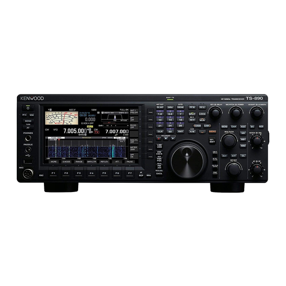
Kenwood TS-890S In-Depth Manual
Hf/50mhz transceiver
Hide thumbs
Also See for TS-890S:
- Instruction manual (196 pages) ,
- Command reference manual (77 pages) ,
- Setting manual (73 pages)
Table of Contents
Advertisement
Quick Links
Advertisement
Table of Contents

Related Manuals for Kenwood TS-890S


Summary of Contents for Kenwood TS-890S
- Page 2 Corporation, in writing, prior to redistributing this manual on a There is always a risk of losing your important data by a personal web page or via packet communication. Furthermore, transceiver failure, occurrence of an unforeseen contingency, any reselling, assigning or transferring of the software is also erroneous operation or faulty behavior of the transceiver. strictly prohibited without embedding the software in KENWOOD The data, such as the operating information, recorded audio, product memories. messages, configuration data, and logs, must be backed up as necessary by yourself and stored in an external storage device COPYRIGHTS FOR RECORDED AUDIO such as a USB flash drive. The broadcast content recorded in this transceiver may not be reused, except for personal use, without prior consent of the URL AND CONTACTS OF JVC KENWOOD CORP. rights holder under copyright laws. The latest URL and contacts of JVC KENWOOD Corporation at the time when this manual was written are described in TRADEMARKS this manual. Due to changes of social circumstances or the management environment, the URL and contacts of • KENWOOD is a registered trademark of JVC KENWOOD JVC KENWOOD Corporation may change from time to time. Corporation. • Microsoft , Windows , and the Windows logo are the ® ®...
-
Page 3: Table Of Contents
TABLE OF CONTENTS 01 PROLOGUE 06 MPU PERIPHERAL CIRCUIT About the Release of the TS‑890S ........1 MPU Peripherals for Transceiver Control ......28 Features of the TS‑890S ..........2 MPU Peripherals for Application Control ......28 MPU Peripherals for Operation Panel Control ....28 02 RECEPTION CIRCUIT 07 DSP Receiver Configuration ............ 3 First Mixer ................ 5 Features of TS‑890S DSP Technologies ......29 Roofing Filters ..............5 DSPs and Peripheral Hardware ........29 Signal Processing in the IF Stage ........30 What is a Roofing Filter? ............5 Roofing Filters .................6 IF‑AGC ..................30... - Page 4 TABLE OF CONTENTS CW/RTTY/PSK Decoding/Encoding Available Only for the 11 MECHANICAL STRUCTURE Main Unit ............... 55 Decoding/Encoding of CW Morse Code ........55 Internal Structure ............82 Decoding/Encoding of RTTY/PSK .........56 Cooling ................83 Data Mode Convenient for Operation Using an External Lift‑up Mechanism of the Front Bases ......85 Device ................57 Operability ..............86 Switching the Input Sound Source .........57 TFT Display and Touch Panel ........88 USB Keying ................58 Main Control Knob Mechanism ........89 Functions Related to the Internal Memory/USB Flash Drive/File Management .
-
Page 5: 01 Prologue
The TS-890S, the latest addition to the glorious history of the TS-800 family, has been developed not only to complement the TS-990S and TS-590 series, but attention has also been devoted to the “basic reception performance”, which is the main interest of our customers. -
Page 6: Features Of The Ts-890S
01 prologue As described above, TS-890S has been developed to inherit the DNA of KENWOOD’s HF transceivers and as a model that forms the core of the TS-x90 series. It is an advanced transceiver for practical use that has evolved in its own ways as a full-fledged successor of the TS-800 family, and not just a modified version of the TS-990S or TS-590 models. -
Page 7: 02 Reception Circuit
02 RECEPTION CIRCUIT Receiver Configuration The TS-890S is the single-band transmitter-receiver of the down-conversion method, which is refined and diverted from the circuit configuration of the main band receiver of the top-model TS-990S. During transmission, the receiver behavior stops. Also, the bandscope circuit shows the status of IF signals during reception and transmission. - Page 8 02 RECEPTION CIRCUIT The received signal which was input from the antenna comes into the front-end block of the receiver through the antenna switching circuit. The bandpass filter for the selected receive band eliminates interfering signals outside the band. The received signal is amplified by a pre-amplifier and is then converted to the first IF signal (8.248 MHz) by the first H-mode mixer having high IP characteristics.
-
Page 9: First Mixer
RECEPTION CIRCUIT 02 First Mixer For the first mixer, the “H-mode mixer” with less distortion is refined and diverted from the one adapted in the TS-990S main receiver, and the conversion loss has been reduced and matching of the frequency characteristics of the mixer input port by the wide bandwidth is enabled. -
Page 10: Roofing Filters
02 RECEPTION CIRCUIT Roofing Filters Four types of roofing filters are equipped as standard as narrowband filters of high IP characteristics implemented by the full down-conversion method. In addition, to meet the needs for narrower band filters, optional filters are available (sold separately) and supported by a mounting slot. -
Page 11: Agc Circuits
The AGC circuit is required to have low noise and a wide dynamic range, wide control range, and linearity to the control. The TS-890S implements high-precision AGC response characteristics with the combination of an AGC circuit in which a dual-gate MOSFET is used and the correction process made by DSP. The “AGC Circuit with a Dual-Gate MOSFET”... -
Page 12: Optimization Of Gain Distribution
The IARU (International Amateur Radio Union) standard scale requires -73 dBm for S9. However, concerning the S meter needle deflection, on all of the KENWOOD transceivers, it is -81 dBm for S9 in the 14 MHz band while a pre- amplifier is on. -
Page 13: Noise Level
RF Gain Adjustment KENWOOD HF-band transceivers are configured with our consistent philosophy to balance the levels, such as the sensitivity, S meter needle deflection, pre-amplifier gain, gain correction, and other factors, thus the internal noise may be conspicuous if the input level from an antenna is low. -
Page 14: Noise Blankers
Features of the NB1 and NB2 The TS-890S has two noise blankers; NB1 for analog processing and NB2 for digital processing by DSP. NB1 is effective for short-cycle pulses, such as ignition noise. NB2 is effective for noise that the analog noise blanker (NB1) cannot follow. -
Page 15: Auxiliary Circuits
Medium Wave Band Sensitivity Risers Just as in past transceivers, the TS-890S has attenuators of approximately 20 dB for the medium wave band (522 kHz to 1.705 MHz) (as the factory default, the sensitivity is lowered by approximately 20 dB by the attenuators). In the medium wave band, there are a number of strong radio waves and there may be medium wave band signal input that is excessive for low-band antennas. -
Page 16: 03 Transmission Circuit
03 TRANSMISSION CIRCUIT IF Circuit for Clean and Stable 100 W Output Power A signal modulated and multifariously processed in the DSP is fed as the 24 kHz (modes other than FM) or 36 kHz (FM mode) transmit first IF signal by a D/A converter, which is then converted by a diode mixer used for both transmission and reception to 8.248 MHz. -
Page 17: High-Speed Relay-Controlled Antenna Tuner
Fig. 14 Transmit IMD Characteristics (14.2 MHz, 100 W output power) output power) High-speed Relay-controlled Antenna Tuner The TS-890S has a high-speed relay-controlled antenna tuner, which digitally controls in a combination of capacitors of different capacitance through switching relays. The digital control achieves high-speed tuning. -
Page 18: Linear Amplifier Control
03 TRANSMISSION CIRCUIT Linear Amplifier Control Linear amplifier control can be used for switching between transmission and reception of devices such as the linear amplifier and transverter. REMOTE Connector The REMOTE connector is a 7-pin DIN type connector, the same as our conventional transceivers. The LKY (Linear amplifier Keying) terminal (pin 7) is equipped with a logic to output 12 V on transmission and a logic for short-circuiting to ground on transmission according to the linear amplifier menu setting which will be described later. -
Page 19: Linear Amplifier Menu Settings
Voltage and current not higher than DC 50 V and 100 mA respectively can be controlled. The TS-890S linear amplifier control relay functions on transmission if “Internal Relay Control” is enabled in the Linear Amplifier Menu. The linear amplifier control relay assumes that the TL-922 (discontinued) is standing by and can be connected as-is to the TL-922. - Page 20 03 TRANSMISSION CIRCUIT ● Tx Delay Time (CW/FSK/PSK) For configuring the delay time that is enabled when in the CW/ FSK/PSK non-audio mode. ● Tx Delay Time (SSB/FM/AM) For configuring the delay time that is enabled when in the SSB/FM/AM audio mode. This can be configured to a setting that is different from that for the non-audio modes.
-
Page 21: Alc
The ALC signal is a signal output from an external device that shifts the voltage to the negative side (for KENWOOD transceivers) when the transmit power reaches the range to be restricted from the external device standpoint. External devices generally have voltage adjustment VRs (variable resistors). -
Page 22: Transmit Power Limiter
03 TRANSMISSION CIRCUIT Transmit Power Limiter The transmit power limiter prevents the transmit power from exceeding the pre-configured transmit power level. It can be turned on or off by pressing the F [MAX-Po] key. The power limit can be configured for each band as well as for each of the SSB, CW, FSK/PSK, AM/FM and DATA modes. -
Page 23: Alc Operation When An External Device Is Connected
The “Connection Block to an External Device for ALC Signal Input” diagram shows the connection block with an external device when ALC signal is input from the external device to the TS-890S as well as changes in the output level with the ALC voltage. -
Page 24: Drv Terminal
03 TRANSMISSION CIRCUIT DRV Terminal The output level from the DRV connector is approximately 0 dBm (1 mW). Power detection is performed for output from the ANT terminal, and the output will not exceed the preconfigured level due to activation of ALC. However, the output level will fluctuate as ALC will not be activated for the DRV terminal output if ALC signal is not input from the external device. -
Page 25: Protections
Not only does a high antenna SWR impede efficient radio wave radiation, distortion may occur in the final circuit due to the reflected waves, and the TS-890S or the antennas may be damaged as a result. To prevent such a problem from occurring, a protection circuit is implemented to reduce the transmit power to reflected waves. -
Page 26: 04 Local Oscillator Circuit
04 LOCAL OSCILLATOR CIRCUIT Local Oscillator The local oscillator circuit in the TS-890S is configured to obtain the characteristics needed for each signal, such as the VCO (Voltage Controlled Oscillator) division type for the first and second oscillator signals and DDS (Direct Digital Synthesizer) direct system for the third local oscillator. - Page 27 local oscillatior circUit 04 Fig. 27 100 MHz OSC C/N Characteristics First Local Oscillator Signal C/N Reception of 14.0 MHz Signals Reception of 50.0 MHz Signals Fig. 28 First Local Oscillator Signal C/N Characteristics...
-
Page 28: 05 Antenna Control Circuit
Signaling Paths The TS-890S has two antenna connectors, ANT1 and ANT2, an RX IN and an RX OUT connector that can be used for reception-only antenna input or connection of an external filter, as well as ANT OUT connector that can be used to connect the receiver to an external device. -
Page 29: Ts-890S User Report
Menu [67]: Select 115200 bps Enable the split operation mode on the TS-890S and set VFO A/B. When TX VFO on the TS-890S is altered, the RX frequency on the TS-590G will change automatically. To change the TX frequency on the TS-890S, set XIT to ON and turn the RIT/XIT knob. - Page 30 The photo below shows the display screens on the TS-890S and TS-590 with split transfer feature 1 enabled. The quickest way to enter the split operation mode is to long-press the SPLIT button on the TS-890S until the band direct key starts flashing. Next, push the frequency to offset for the transmitting call to enter the split mode for simultaneous reception of two bands.
- Page 31 This is a lavish setup, but for users who already have a TS-590 and would like to enjoy smooth simultaneous dual- band reception with the TS-890S, then there is no need to let go of their current TS-590 unit. For users who do not...
-
Page 32: 06 Mpu Peripheral Circuit
06 MPU PERIPHERAL CIRCUIT The MPU peripheral circuit of the TS-890S is made up of the following parts. • MPU peripherals for transceiver control • MPU peripherals for application control • MPU peripherals for operation panel control MPU Peripherals for Transceiver Control... -
Page 33: 07 Dsp
We have been providing “Quality” in communications that cannot be realized only by analog circuits. The development concept of the DSP for the TS-890S is the ability of its application to actual operations. It has gone through a thorough brush-up to deliver the best performance under harsh and unfavorable conditions. -
Page 34: Signal Processing In The If Stage
Fig. 32 IF Stage Block Diagram AGC loops of the TS-890S are placed before and after the interference rejection, such as an IF filter or notch filter. The AGC loop of the preceding stage functions to prevent signals whose level is higher than the reference from being input to the A/D converter for the IF input and is called the out-band AGC loop. -
Page 35: Agc Quick Recovery
KENWOOD Existing Model Time (s) Time (s) Fig. 33 Comparison of Received CW Waveforms: Conventional Transceiver vs. TS-890S AGC Quick Recovery AGC Quick Recovery is a newly-added feature on the TS-890S. When pulse noise generated by sources such as an electric fence is received, the in-band AGC attacks the pulse noise to lower the gain of the AGC amplifier. -
Page 36: If Filter
07 DSP IF Filter As the main band limitation filter, the TS-890S is equipped with roofing filters for the analog stage as well as DSP digital IF and AF filters (in addition to these, there are also audio peak filters, etc.). - Page 37 SSB mode. Employing the digital filter design technology that we have accumulated, the TS-890S now offers a filter and IF-AGC design that minimizes ringing as well as impact on the sound quality. As the roofing filter settings for the analog circuit vary in tandem with the specified filter bandwidth characteristics, interference by adjacent signals is less likely to occur when a narrow band of 500 Hz or lower is configured in the CW mode.
-
Page 38: Interference Rejection
● Noise Blankers The TS-890S has two noise blankers, NB1 and NB2. NB1 is the noise blanker for the analog circuit. NB2 is the noise blanker for digital signal processing. NB2 offers two modes, Type A and Type B, which can be employed for different situations. - Page 39 DSP 07 NB2 affects the noise that cannot be processed by the analog circuit; however, there may be a case where it cannot suppress the noise depending on the strength of the desired signal and characteristics of the pulse noise. In such a case, by using noise reduction together, the receiving status may be improved.
-
Page 40: Reception
The optimal design of the PSN system is determined by the characteristics of the IF filter that comes with the transceiver. If a steep and large-attenuation filter similar to the IF filter of the TS-890S is used, the number of reverse bandwidths to be canceled by the PSN system is very small. -
Page 41: Af Filter
RX equalizer. Emphasis was also placed on the AF filter design of the TS-890S to process the signal in the stage preceding demodulation in the SSB, CW, FSK and PSK modes. -
Page 42: Audio Peak Filter
07 DSP ● AM and FM Modes In the AM mode, the AF filter is placed after demodulation. It adopts a mechanism that switches the IF filter bandwidth when the high-cut frequency is switched. Meanwhile, switching the low-cut frequency alters only the AF filter setting. In the AM mode, extending the bandwidth only with the IF filter may cause the audio to sound distorted. -
Page 43: Noise Reduction
The TS-890S employs a technique to reduce musical noise (tonal “blip blip” sound that is minutely segmented) that is inherently generated as a result of the spectral subtraction process. With this technique, musical noise is largely reduced, and influence by digital processing that is incidental to noise reduction is lowered. - Page 44 SSB mode. It is positioned in the TS-890S as a noise reduction method for non-audio signals. The graphs below show how NR1 improves the S/N ratio of a tone signal with the line enhancer method.
- Page 45 DSP 07 ● NR2 (SPAC Method) The NR2 is for noise reduction with a speech processing system by using the Autocorrelation function, which is called SPAC (Speech Processing system by use of the Auto Correlation function). This system enables to detect periodic signals contained in the received signal and to piece together the periodic signals detected as the received signal to be reproduced.
-
Page 46: Beat Canceler
07 DSP Beat Canceler While the notch filter processes signals in the IF stage, the beat canceler suppresses the beat in the AF stage. Beat canceler is effective when there are multiple beat signals. The beat canceler employs an adaptive filter technique which is of the same type as that for the NR1 line enhancer method. -
Page 47: Signal Processing By Morse Code Decoder
DSP 07 Signal Processing by Morse Code Decoder The Morse code decoder is a feature that decodes Morse codes received in the CW mode and displays them as text on the screen. When we first introduced the Morse code decoder, which was on the TS-590G series, there were cases where erroneous decoding results were displayed under certain reception conditions. -
Page 48: Transmission
07 DSP On the TS-890S, the processing block has been modified to enable more accurate decoding. Envelope Threshold RX IF IF Filter Limitter Delay Detection Judge Fig. 54 Detection Block of Morse Code Decoder on TS-890S Envelope detection is performed with Morse codes controlled at a constant level via AGC processing. The level assessment by AGC are then synchronized with the threshold assessment of envelope detection to enhance the decoding rate. - Page 49 DSP 07 Frequency (Hz) Fig. 56 Characteristics of the SSB TX Filter TX monitoring audio is generated by detecting the IF signal in the final stage of DSP. This enables monitoring of audio signals that are close to those to be output as radio signals. ●...
-
Page 50: Microphone Gain Control
Speech Processors The TS-890S is equipped with a speech processor in the IF stage in the SSB mode (hereinafter referred to as “IF speech processor”) and a speech processor in the AF stage in the AM and FM modes (hereinafter referred to as the “AF speech processor”). - Page 51 DSP 07 The graphs below show modulated signal waveforms while the IF speech processor is inactive and if waveforms of modulated signals which are compressed respectively with “Soft” configured or with “Hard” configured. If there is substantial noise or if it is not easy to distinguish a target signal and noise, adjusting the reference level of the bandscope will facilitate you to distinguish the target signal easily.
-
Page 52: Other Functions
Voice Guidance The TS-890S comes with a built-in voice guidance function in the DSP which only requires the TS-890S unit to make use of the feature. It is also equipped with a guidance speed control function for controlling the speed via digital signal... -
Page 53: 08 Bandscope
“adjacent signal discriminability (frequency resolution)”, has become an important feature for more practical use of the transceivers. To further enhance the practical use of the bandscope on the TS-890S, we have significantly brushed up both processing of signals from the RF unit as well as the software. -
Page 54: Reference Level
● Center Mode (CENTER MODE) The RX frequency is always fixed at the center of the horizontal axis of the bandscope in this mode. The TS-890S adopts a straight-line waterfall display when the frequency is altered. Changing the frequency displaces the flow of the bright lines that indicate the signal intensity horizontally, and tuning is possible by overlapping it with the RX marker. -
Page 55: Gradation Settings
08 bandscope Gradation Settings In the waterfall display, the signal intensity is indicated using a color gradation of blue to green (weak), yellow to red (medium) and white (strong). Variation of the color with the signal intensity can be configured in Menu 8-04 “Waterfall Gradation Level”. -
Page 56: 09 Software
Display Function for Actual Operation The TS-890S has a 7-inch TFT color display, which is the same size as the display size of the top-model TS-990S. The TS-890S also supports a filter scope display, bandscope display, audio scope display, and transmission digital meter, in addition to basic information such as frequency, mode, and S meter. -
Page 57: Transmission Digital Meter
Software 09 Transmission Digital Meter During transmission, some situations need to be checked not just for the transmit power, but also for the ALC status and the SWR status. In these cases, the methods are selecting the digital meter type for the meter displayed on the top-left, or previously selecting the analog meter type and making the transmission digital meter appear. -
Page 58: Operability Improvements For Split Operation
Band Direct Key Configuration for Split The TS-890S allows you to switch the band or band memory while retaining the split state when switching the band or band memory by pressing the band direct key during split operation. The configuration is convenient when pursuing a DX-pedition for multi-band/-mode operation because a split frequency and mode can be individually configured to each band memory of each band*. -
Page 59: Split Frequency Reception By Using An External Sub Receiver
Split Frequency Reception By Using an External Sub Receiver By connecting another transceiver (TS-890S or TS-590S/ TS-590SG) as a sub receiver, and then using the split transfer A function, the split transmission frequency information is transferred to the sub receiver, and dual band reception can be assisted. -
Page 60: Decoding/Encoding Of Rtty/Psk
09 Software Decoding/Encoding of RTTY/PSK The TS-890S is equipped with an internal demodulator and decoder (RTTY supports 170 Hz shift only), allowing RTTY and PSK operations without using a PC. PSK also supports PSK63 (BPSK only). By connecting a USB keyboard, operations can be efficient and comfortable. -
Page 61: Data Mode Convenient For Operation Using An External Device
Software 09 Data Mode Convenient for Operation Using an External Device As well as a microphone terminal, the rear panel has a variety of input and output interfaces such as an analog audio input and output, a USB audio interface, and a LAN (VoIP) interface. The demodulation path by a combination with DATA mode in each mode of SSB/FM/AM is free to be configured. -
Page 62: Usb Keying
09 Software USB Keying The TS-890S supports PC applications which control each behavior for CW keying, RTTY frequency shift, and PTT/ SEND (switching of transmitting and receiving) by using the RTS/DTR signal of the COM port. Each behavior can be assigned to the RTS signal and DTR signal of the 2 virtual COM ports (Standard and Enhanced) which can be used when the TS-890S is connected to a PC by using a USB cable. -
Page 63: Selection Of Data Storage Location
Software 09 Selection of Data Storage Location By default, the transceiver saves in the internal memory (the maximum storage space is 1 GB). The transceiver can save in the USB flash drive connected to the transceiver by changing the configuration. The storage location is changed in “File Storage Location”... -
Page 64: Copying From The Internal Memory To A Pc
Press F4 [OK] after the item to copy is selected to display the following screen: When this screen is displayed, “TS-890S” appears as a removable device on the Explorer of the PC connected to the TS-890S by using a USB cable. -
Page 65: Other Useful Functions
Clock Setting Function that uses an NTP Server Connecting the TS-890S to a network enables the clock setting using an NTP server. If an NTP server is specified once, the clock can be adjusted by a single touch. Enabling the automatic time correction function automatically corrects the clock when the power is on and approximately every 24 hours after the power is on. -
Page 66: Transverse Dial Display In Swl Mode
*Transmission is not available in SWL mode. Firmware Updating The firmware of the TS-890S can easily be updated by using a USB flash drive or a PC. The latest firmware information is provided on the JVC KENWOOD website. There are two firmware updating methods available: ●... -
Page 67: Pc-Control
Software 09 PC-Control The freeware ARCP-890 is available as a radio control program dedicated to the TS-890S, and the PC command reference guide is openly available, and we suggest trying a self-programmed application for your own purpose. The following are the descriptions for a self-programmed application and some instructions and tips for the PC commands ●... - Page 68 ● Acquiring the Transceiver Status Changes (Operating Frequencies, etc.) in Real Time The Auto Information (AI) function is used. Activating the Auto Information function by executing the AI command notifies the PC of the TS-890S status changes in real time.
-
Page 69: Kns Operation Without Using The Host Pc
Software 09 KNS Operation without using the Host PC For the TS-890S series, the remote control through a LAN or the Internet is available by using the radio control program ARCP-890 and KENWOOD NETWORK COMMAND SYSTEM (KNS). Fig. 70 Remote Control through the Internet Fig. -
Page 70: Windows Software
09 Software The conventional system, where the TS-890S is connected to the Internet via a PC (host PC) placed at the host station, can also be selected. In this conventional system, the ARHP-890 (radio host program) and the ARVP-10 (VoIP software) are required. -
Page 71: System Configurations
Software 09 System Configurations The typical system configurations that use the TS-890S and Windows software are described below. Refer to “TS-890S KENWOOD NETWORK COMMAND SYSTEM Setting Manual” which describes detailed information on the configuration method for remote control. ■ Controlling the TS‑890S from an Adjacently‑placed PC (with a Microphone Connected to the TS‑890S and an Internal Speaker) - Page 72 ARCP-890 and Microphone and Audio signal Windows sound speaker connected driver to a PC Note: ◆ Configure “On (LAN)” in “KNS Operation (LAN Connector)” of the TS-890S ● Using the USB connector TS‑890S Connection Signal Type Method Software Hardware Hardware...
- Page 73 Note: ◆ Configure “On (Internet)” in “KNS Operation (LAN Connector)” of the TS-890S. ◆ When the ARHP-890 and TS-890S are connected by a USB-B connector or COM connector, the bandscope screen refreshes at a slower speed. ◆ Even when the USB‑B connector is used for audio signal I/O on the host station side, the ARUA-10 is not used...
-
Page 74: New Option Arcp-890 (Radio Control Program For Ts-890S) (Free Software Application)
Basic Specifications Inherited from the ARCP‑990 The ARCP-890, equivalent to the ARCP-990 for the TS-990S, is designed to be able to operate most of the TS-890S functions. Furthermore, it also conforms to the new functions of the TS-890S. User Interface The ARCP-890 has its user interface languages in both Japanese and English. -
Page 75: New Option Arhp-890 (Radio Host Program) (Free Software Application)
This is used when the internal TS-890S KNS server function is not used. The ARHP-890 is a free software application and can be downloaded free of charge from the KENWOOD website. Refer to “TS-890S KENWOOD NETWORK COMMAND SYSTEM Setting Manual” which describes detailed information on the configuration method for remote control. -
Page 76: Arua-10 (Usb Audio Controller) (Free Software Application)
An audio signal input into the microphone of the PC is input to the modulation input of the USB audio device in the TS-890S. The audio signal output from the RX output of the USB audio device in the TS-890S is output to the speaker of the PC. Fig. 73 Example of the ARUA-10 and Peripheral Connections... -
Page 77: Arvp-10H/Arvp-10R (Radio Voip Program) (Free Software Application)
There are two software applications released to divert the audio signal with the network connection: the ARVP-10H, which provides the VoIP function on the host station site where the TS-890S is placed, and the ARVP-10R, which provides the VoIP function on the remote station site that remotely controls the TS-890S. -
Page 78: Virtual Com Port Driver
• Start the Windows Device Manager. • The following two COM ports appear in “Ports (COM & LPT)” of the Device Manager when the TS-890S is connected through USB cable. “Silicon Labs CP210x USB to UART Bridge (COM x)” “Silicon Labs CP210x USB to UART Bridge (COM y)”... - Page 79 A COM port number will change upon switching a USB port to another USB port of a PC that is connected to the TS-890S by using a USB cable. In this case, confirm again a current COM port number with the above procedure.
-
Page 80: 10 Terminal Functions
10 terminal FUnCtiOnS aCC 2 Connector This is an accessory terminal for connecting the TS-890S with an external device. This terminal is equipped with the following interfaces. • RX audio output (output level can be configured in the menu) • Squelch control output • TX audio input (input level can be configured in the menu) • PTT (SS) input (Transmits microphone audio input. This is a convenient feature when using devices such as a footswitch.) • PKS input (Transmits audio input from an external device. Transmission with the microphone input muted is possible. This is a convenient feature for data communication. -
Page 81: Display (Dvi-I) Connector
terminal FUnCtiOnS 10 DiSPlaY (DVi-i) Connector This connector is used for connection with an external monitor. It supports both digital signal and analog signal outputs. The DISPLAY connector employs a DVI-I connector which is able to deliver high image quality when used together with a DVI digital cable. -
Page 82: Lan Connector
10 terminal FUnCtiOnS lan Connector This connector is used for connection to a PC or LAN when operating using the KNS (KENWOOD NETWORK COMMAND SYSTEM) or to enable automatic time correction using the NTP (Network Time Protocol) server. It supports the 100BASE-TX and 10BASE-T LAN interface. Broadband Router or Hub PC 1 ARCP-890 Radio Control Program Internet Carrier and Service Provider Ethernet Cable (Straight Type)... -
Page 83: Meter Jack
PADDLE, KEY Jack The PADDLE jack is placed at the front of the unit for greater ease of use. The TS-890S has an internal electronic keyer which allows you to use a paddle simply by connecting it to the PADDLE jack in front. The KEY jack at the back is configured to “Straight Key” by default. It can be used for input of keying signals from an external device or the straight... -
Page 84: Usb Connector (Usb-A)
There is one USB connector each in front and at the back, which can be used in the same way. It will be convenient to use the front connector for a USB flash drive and the rear connector for connecting a PC keyboard. ● Example of Using a USB Flash Drive Through the connector, configured settings and voice data created on the TS-890S can be copied to a USB flash drive, and files can also be loaded into the TS-890S. At the same time, it is possible to capture screenshots and save them to the USB flash drive. Timer recording is also supported. -
Page 85: Usb Connector (Usb-B)
USB Connector (USB-B) This connector is used for connecting a PC. It supports the use of the ARCP-890 for remote control of the TS-890S as well as input and output of TX and RX audio to and from the PC using the USB Audio feature. It can also be used for updating the firmware (firmware update can also be performed using a USB flash drive). -
Page 86: 11 Mechanical Structure
This chapter describes the internal structure of the TS-890S as well as the board (UNIT) layout. The TS-890S comes with a DC/DC unit at the top left of the chassis and the final unit at the top right. The lower layer is further divided into two layers, with the DSP unit and control unit located at the bottom left and the PLL unit and TR/RX unit at the bottom right. -
Page 87: Cooling
Cooling The cooling mechanism is such that heat emitted from the final unit of the TS-890S is directed conveyed to the chassis underneath, which is then discharged from the back of the cooling fan motor using the fin that is located on the reverse side of the final unit. - Page 88 Although the TS-890S adopts a heavy-duty design, the life of electronic parts in general (not just KENWOOD products) tends to shorten when the temperature is higher. To enable long-term use of the TS-890S, it is recommended that it be used at an appropriate output according to the situation.
-
Page 89: Lift-Up Mechanism Of The Front Bases
Consequently, the front base can support the heavy weight of the TS-890S with sufficient allowance and without adding stress to the rotary arm. -
Page 90: Operability
The well-received layout of the TS-990S, which allows direct access to the keys and rotary knobs, is also adopted on the TS-890S. By actually trying out the TS-890S, you will be able to have a direct feel of the positioning of the keys and rotary knobs, which are divided into separate functional blocks. - Page 91 Fig. 91 Key and Rotary Knob Allocation The TS-890S adopts the same structure as the premium TS-990S with primary emphasis on the texture to optimize the operability of the keys. Resin keys that are coated or plated are also used to create a premium feel.
-
Page 92: Tft Display And Touch Panel
TFT Display and Touch Panel The TFT display of the TS-890S employs a 7-inch TFT LCD with an LED backlight which takes into consideration the operating environment, image quality and life-span. The TFT display is long-life and free from optical irregularities, and provides beautiful imaging. -
Page 93: Main Control Knob Mechanism
MECHANICAL STRUCTURE 11 Main Control Knob Mechanism The main control knob is made of aluminum that is NC-machined. Its shape was designed by taking into account the rotational balance and suppression of eccentricity. The design results in a superb operational feeling of a weighted, smooth, and accurate touch. The surface of the main knob is machined by a specially-designed tool bit and is finished so that it has a radially lucent spin-cut pattern. -
Page 94: Sp-890
12 SP-890 This premium external speaker for communications enables system enhancement when it is used with the TS-890S. Appearance and Features The front panel is aluminum die-casting and the speaker net is a punched metal sheet intended for better sound transit to secure good sound quality by its fundamental structure. -
Page 95: Built-In Passband Filter
SP-890 12 Built-in Passband Filter The built-in passband filters, which are also popular on the SP-990, are designed with optimized values for the full-range speaker. High-cut and low-cut filters are installed, and the optimal filters can be selected according to the mode, such as SSB or CW operation. - Page 96 TS-890S In-depth Manual May 17, 2019 CA-337W-E96 Copyright © 2019 All Rights Reserved.
Need help?
Do you have a question about the TS-890S and is the answer not in the manual?
Questions and answers