Table of Contents
Advertisement
Quick Links
Stock #
6280B
6281B
© Blonder Tongue Labs, Inc.
All Rights Reserved. Specifications subject to change without notice. All trademarks are property of their respective owners.
Model Name
Description
AQT8-IP
8x8VSB/QAM Input and IP Outputs
AQT8-QAM/IP
8x8VSB/QAM Input and QAM/IP Outputs
ISO 9001:2015 Certified
AQT8 Series
AQT8 Series
P/N: 651247000A | Rev: 110819
Advertisement
Table of Contents

Related Manuals for Blonder tongue AQT8 Series


Summary of Contents for Blonder tongue AQT8 Series
- Page 1 8x8VSB/QAM Input and IP Outputs 6281B AQT8-QAM/IP 8x8VSB/QAM Input and QAM/IP Outputs © Blonder Tongue Labs, Inc. P/N: 651247000A | Rev: 110819 ISO 9001:2015 Certified All Rights Reserved. Specifications subject to change without notice. All trademarks are property of their respective owners.
- Page 2 Returning Product for Repair (or Credit) A Return Material Authorization (RMA) Number is required on all products returned to Blonder Tongue, regardless if the product is being returned for repair or credit. Before returning product, please contact the Blonder Tongue Service www.blondertongue.com Department at 1-800-523-6049, Ext.
-
Page 3: Table Of Contents
AQT8 Series User Manual Table of Contents SECTION 1 – GENERAL & SAFETY INSTRUCTIONS ....................... 5 SECTION 2 – PRODUCT SUMMARY ..........................6 2.1 REVISION HISTORY & REASON ..........................6 2.2 PRODUCT APPLICATION & FEATURES ........................6 2.3 PRODUCT SPECIFICATIONS ............................ 9 SECTION 3 –... - Page 4 4 AQT8 Series User Manual Table of Contents (continued) SECTION 10 – EAS CONFIG ............................28 SECTION 11 – GENERAL AND SYSTEM CONFIGURATION................... 29 11.1 “TIME” TAB ................................29 11.2 “LOG” TAB ................................30 11.3 “UPDATES” TAB ..............................31 11.4 “SYSTEM” TAB ..............................32...
-
Page 5: Section 1 - General & Safety Instructions
å Do not use accessories or attachments not recommended by Blonder Tongue, å Do not overload wall outlets or extension cords, as this can result in a risk of fire as they may cause hazards, and will void the warranty. -
Page 6: Section 2 - Product Summary
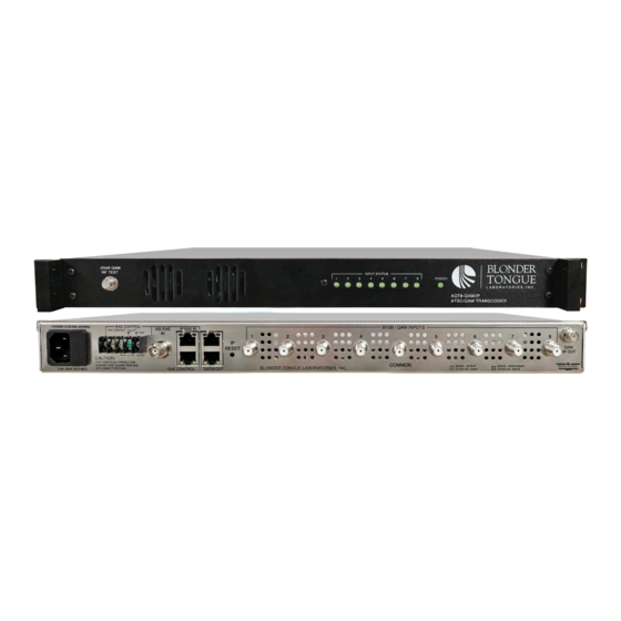
Application: The AQT8 Series (AQT8-QAM/IP and AQT8-IP) allows the user to create a custom IP and QAM output from off-air and/or QAM input sources. The unit accepts eight 8VSB off-air or QAM sources and simultaneously outputs these SPTS and/or MPTS programs in IP and/or QAM. - Page 7 AQT8 Series User Manual 2.2 Product Application & Description (Continued) -20dB QAM RF TEST (AQT8-QAM/IP Only): "F" female connector for QAM RF output signal, 20dB lower than the actual QAM RF output. Used for test purposes, without taking the unit out of service.
- Page 8 8 AQT8 Series User Manual 2.2 Product Application & Description (Continued) DATA OUT: RJ45 for 1000Base-T Ethernet (GigE) interface for IP DATA outputs. IP RESET: When pushed and held for about 10 seconds, temporarily resets the IP address, Usernames, and Passwords to Factory Default values as follows: IP address = 172.16.70.1...
-
Page 9: Product Specifications
AQT8 Series User Manual 2.3 Product Specifications Input Output Connectors 8VSB/QAM: 8x “F” Female Connectors: 1x RJ45 (rear-panel) 1x Common “F” Female Standard: 1000Base-T Ethernet (GigE) with Internal Active Splitter UDP: Supported Address Assignment: 64x IPv4 SPTS address & port numbers 8VSB Mode 8x IPv4 MPTS address &... -
Page 10: Section 3 - Unpacking And Connecting The Unit
3.2 Installation and Power-Up The AQT8 Series is designed to be installed in a standard 19-inch (483 mm) rack (EIA 310-D, IEC 60297, and DIN 41494 SC48D). To install, secure the unit's front panel to the rack by inserting four (4) machine screws, with cup washers, through the four (4) mounting holes in the front panel. -
Page 11: Accessing The User Interface Via The Web Browser
AQT8 Series User Manual 3.3 Setting up Ethernet Access (Continued) (e) A dialog box entitled ”Internet Protocol Version 4 (TCP/IPv4) Properties” will appear. Select the “Use the following IP address” option and enter the following addresses: IP address: 172.16.70.2 Subnet mask: 255.255.255.0 No need to enter a value for the Default Gateway. -
Page 12: Section 4 - Status
12 AQT8 Series User Manual Section 4 – Status The “Status” tab (Figure 4) displays the general health and unit information at a glance. The information is provided as a quick way to monitor the unit or assist with troubleshooting any issues that may arise. -
Page 13: Detected Issues
AQT8 Series User Manual 4.2 Detected Issues In the section entitled “Detected Issues”, the following system information is indicated: Figure 4.2 - “Status” Tab - Detected Issues If any issues arise, the problem will be shown here and the color will correlate to the urgency of the issue. When there are no issues, the text will say “No issues detected”... -
Page 14: Rf Output Status
14 AQT8 Series User Manual 4.5 RF Output Status In the section entitled “RF Output Status”, all 8 RF Output Transport stream sources are displayed along with their output QAM RF channel and frequency. Figure 4.5 - “Status” Tab - RF Output Status 4.6 System Information... -
Page 15: Section 5 - Rf Input
AQT8 Series User Manual Section 5 – RF Input The “RF Input” tab (Figure 5a) is “user-configurable” with the following parameters and status information: Figure 5a - “RF Input” Tab RF Source: Indicates the physical port of the 8 RF inputs. -
Page 16: Section 6 - Cherry Picking
16 AQT8 Series User Manual Section 6 – Cherry Picking Once the user clicks on the Cherry Picking tab on the menu, the options within “TS (Transport Stream) Select” tab (Figure 6) are shown. The controls on this screen allows the user to construct custom multiplexed transport streams (TS). These can be output both QAM and/or IP depending on the model. - Page 17 AQT8 Series User Manual 6.1 TS Select > Configuration Settings and Parameters (continued) O#: Displays as “Other”, indicating the system did not recognize it as an audio or video element. The other icon appears as a pair of files. Here “#” represents the number which helps to differentiate between similar "Other" type streams.
-
Page 18: Ts Select > Adding Additional Programs To Cherry Picked Transports
18 AQT8 Series User Manual 6.2 TS Select > Adding Additional Programs to Cherry Picked Transports Within the “RF Input TS” column and under each numbered RF Input, the user can locate the program(s) available for adding to a Transport Stream under the “Cherry Picked Transports” column. (See Figure 6.2) Figure 6.2 - “TS Select”... -
Page 19: Ts Select > Search Function And Additional Controls
AQT8 Series User Manual 6.3 TS Select > Removing Programs from the Transport Stream Output (continued) Removing Program(s): Click “Remove” and the program will be made available once again within the “RF Input TS” column and removed from the “Cherry Picked Transports” column. In addition, the user is able to click the “Remove All”... -
Page 20: Ts Config > Advanced Configuration
20 AQT8 Series User Manual 6.5 TS Config > Basic Configuration (continued) VCT: Virtual Channel Table (VCT) allows the user to choose from the following options: CVCT: Cable Virtual Channel Table TVCT: Terrestrial Virtual Channel Table OFF: Turns the VCT off. -
Page 21: Ts Config > Output Transports
AQT8 Series User Manual 6.6 TS Config > Advanced Configuration (continued) QAM Status: A read-only parameter indicating the QAM output status. This parameter is set under the “RF Output” tab. The following columns are used to display the PID numbers used for programs within the TS Output. -
Page 22: Ts Config > Global Programs Relative Pid Map
22 AQT8 Series User Manual 6.8 TS Config > Global Programs Relative PID Map The Global Programs Relative PID Map (Figure 6.8), allows the user to offset the PID from the PMT. To open the Map, click the plus sign ( ) next to the Map's title at the top of the Transport Configuration column section. The additional following parameters will then be shown: Figure 6.8 - “TS Config”... -
Page 23: Section 7 - 2:1 Multiplexing
AQT8 Series User Manual Section 7 – 2:1 Multiplexing Once the user clicks on the “2:1 Multiplexing” tab on the main navigation menu, the options within “TS (Transport Stream) Select” tab (Figure 7.1) are shown. The AQT8's 2:1 Multiplexing is capable of running simultaneously with Cherry Pick. -
Page 24: Ts Config
24 AQT8 Series User Manual 7.2 TS Config The “TS Config” tab (Figure 7.2) allows the user to change the TS Bitrate, TSID, VCT, Short Name, Program Number, Major Channel and Minor Channel as well as additional advanced configurations of the Program PID Base and the Next Program PID Base. -
Page 25: Section 8 - Ip Output
AQT8 Series User Manual Section 8 – IP Output The “IP Output” tab (Figure 8) on the main navigation menu allows the user to select programs for IP output. NOTE: Clicking the small arrow ( collapsed; expanded) beside each program will show or hide further choices or read- only data. -
Page 26: Available Output Resources
26 AQT8 Series User Manual 8.3 Available Output Resources The “Available Resources” table (Figure 8.3) displays, in real-time, the remaining available resources after factoring out the current assigned streams to the IP Output. The resources being monitored are as follows: TS Out: Displays the remaining Transport Streams (TS) for each port. -
Page 27: Section 9 - Rf Output
AQT8 Series User Manual Section 9 – RF Output The “RF Output” tab (Figure 9) on the main navigation menu allows the user to select transports for each of up to 8 QAM outputs. NOTE: Clicking the small arrow ( collapsed;... -
Page 28: Section 10 - Eas Config
28 AQT8 Series User Manual Section 10 – EAS Config The “EAS Config” tab (Figure 10) on the main navigation menu allows the user to configure the EAS settings for the unit. The EAS trigger is either by Dry contact closure or Voltage. The EAS source can be IP input or ASI input. -
Page 29: Section 11 - General And System Configuration
AQT8 Series User Manual Section 11 – General and System Configuration 11.1 “Time” Tab The “Time” tab (Figures 11.1a to 11.1d) allows the user to configure the time settings for the system and the event log. Figure 11.1a - “Current Time at Page Load”... -
Page 30: Log" Tab
30 AQT8 Series User Manual 11.1 “Time” Tab (continued) Use Custom NTP Servers: Enable ( ) or Disable ( ) the Custom NTP Servers. Network Time Protocol (NTP) uses one or more IP addresses that the platform can sync time to. When enabled, the three fields under are usable. -
Page 31: Updates" Tab
AQT8 Series User Manual 11.2 “Log” Tab (continued) Message Filter The following message filters can be set to enabled or disabled. Verbose: Enable ( ) or Disable ( ) the Verbose setting. Verbose prevents log messages from being stacked and condensed down into one entry. -
Page 32: System" Tab
32 AQT8 Series User Manual 11.3 “Updates” Tab (continued) Update the Firmware version by clicking the button. The update status and progress will show under the “Status” column. Below is the firmware update as it appears while in-progress (Figure 11.3d) and upon completion (Figure 11.3e). - Page 33 AQT8 Series User Manual 11.4 “System” Tab (continued) System Settings Configuration This section allows the user to back-up and re-load the configuration settings. Resets the unit back to the Factory defaults. It is always recommended to save the existing configuration file before resetting to the default values .
-
Page 34: Admin" Screen
34 AQT8 Series User Manual 11.5 “Admin” Screen The “Admin” screen (Figure 11.5) settings allow a user to change or modify the Username and Password values for the unit while logged in. To access this screen, click the "Admin" link at the top right corner as shown below. - Page 35 10. The cost of the extended warranty is 8% of the purchase price for a 1 or 2 year extension beyond the Blonder Tongue standard warranty. e.g. A product price of $1000 will be $80 for the 1 year (12 mos) and additional $80 for 2 year (24 mos) extension for a total of $160.
- Page 36 BT may determine) any product manufactured by BT which proves to be defective in materials or workmanship or fails to Blonder Tongue Laboratories, Inc. (BT) will at its sole option, either repair or replace (with a new or factory reconditioned product, as BT may the case of software, licensed) by Seller which is defective in materials or workmanship or fails to meet the applicable specifications that are in effect on the date of meet the specifications which are in effect on the date of shipment or such other specifications as may have been expressly...
Need help?
Do you have a question about the AQT8 Series and is the answer not in the manual?
Questions and answers