American Standard SELECTRONIC 6055.105 Installation Instructions Manual
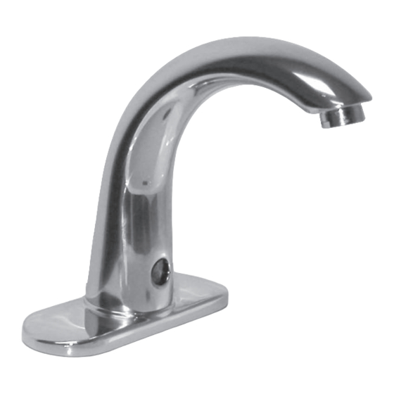
Proximity faucets, cast spout/6" gn spout
Hide thumbs
Also See for SELECTRONIC 6055.105:
- Specification sheet (1 page) ,
- Installation instructions manual (13 pages)
Advertisement
Quick Links
SELECTRONIC™
Proximity Faucets
Cast Spout
6055.104 6056.104
6055.105
6056.105
6055.102
6056.102
6" GN Spout
6055.164 6056.164
6055.165
6056.165
6055.163
6056.163
Certified to comply with ASME A112.18.1M
© 2005 American Standard
M 9 6 8 8 0 9 R ev. 1. 7
NOTE TO INSTALLER: Please give this manual to the customer after installation.
To learn more about American Standard Faucets visit our website at: www.us.amstd.com or U.S.
customer's e-mail us at: sensor@americanstandard.com
For Parts, Service, Warranty or other Assistance,
(855) 752-9259 (In Canada: 1-800-387-0369)
please call
6057.105
6057.102
6057.165
6057.163
(In Toronto Area only: 1-905-3061093)
(In Toronto Area only: 1-905-3061093)
Cast Spout and
Goose Neck Spout
CAUTION: Use only American Standard
supplied cable sets. Using non-AS supplied
cables, or cutting, splicing or modifying any
components will void the warranty.
Product No.'s & Options
Specifications
How to Install
Electrical Hook-up
Maintenance
FAQ,s
Replacement Parts
1
2
2-3
4-6
7-8
9-10
11
Advertisement

Related Manuals for American Standard SELECTRONIC 6055.105


Summary of Contents for American Standard SELECTRONIC 6055.105
- Page 1 M 9 6 8 8 0 9 R ev. 1. 7 NOTE TO INSTALLER: Please give this manual to the customer after installation. To learn more about American Standard Faucets visit our website at: www.us.amstd.com or U.S. customer's e-mail us at: sensor@americanstandard.com...
- Page 2 Thank you for selecting American-Standard...the benchmark of fine quality for over 100 years. To ensure that your installation proceeds smoothly--please read these instructions carefully before you begin. All American Standard Faucets Are Water Tested At Our Factory. UNPACKING Some Residual Water May Remain In The Faucet During Shipping.
-
Page 3: Installation
Fig. 1 Roughing-in Dimensions CAUTION: Use only American Standard supplied cable sets. Using non-AS supplied cables, or cutting, splicing or modifying any components will void the 11-1/8" 6-1/8" warranty. (284mm) (155mm) 131mm 7" 141mm (5-1/8) (179mm) MOUNTING (5-1/2) SURFACE 49mm... - Page 4 MOUNT ENCLOSURE; Fig. 2 Fig. 2 LAVATORY RIM OR 1. Determine location of ENCLOSURE (1). It must be MOUNTING SURFACE located with-in the 14" (356mm) by 21" (533mm) shaded area shown in Figure 2 in order for electrical 14" connections from the spout assembly to be made. (356mm) ENCLOSURE NOTE: ENCLOSURE SUPPLY HOSE is 20".
-
Page 5: Electrical Installation
Faucet Sensor. Fig. 1d. 6. Replace ENCLOSURE COVER (1). Tighten cover screws firmly. INSTALL BATTERY CAUTION: Use only American Standard supplied - P 2 cable sets. Using non-AS supplied cables, or cutting, splicing or modifying any components will void the warranty. - Page 6 AC VERSION; Fig. 2 Fig. 2 Before opening ENCLOSURE CAUTION disconnect AC power supply. NOTE: For AC installation see Fig. 2b. Make power supply connection before mounting ENCLOSURE (1) to wall. 1. Remove ENCLOSURE COVER (1). Fig. 2. 2. Feed the EXTENSION CABLES (2) from the Faucet through the top of ENCLOSURE (3).
- Page 7 Unit #1 Unit #2 Unit #3 Fig. 3 FAUCET WIRE FAUCET WIRE FAUCET WIRE CONNECTORS CONNECTORS CONNECTORS 10 ft. EXTENSION 10 ft. EXTENSION CABLE CABLE *MAXIMUM OF 15 UNITS PER AC POWER SUPPLY. AC POWER SUPPLY 10' MAXIMUM CABLE LENGTH BETWEEN UNITS. FOR AC-VERSION Fig.
-
Page 8: Maintenance
MAINTENANCE Fig 1 HAND WASH SENSOR OPERATION; Fig. 1 When the Sensor detects a user, the water immediately starts to flow. Water flow will stop Two seconds after user is out of sensor range. The off delay allows the user to comfortably move his hands without the flow cycling on to off. - Page 9 HOW TO CLEAN FILTER; Fig. 4 Fig.4 Before opening ENCLOSURE CAUTION disconnect AC power supply. 1. Remove ENCLOSURE COVER. 7/16" SOCKET 2. Close SUPPLY STOP (1) with 4mm Hex wrench. Note: Keep water flowing out of faucet while shutting off. 3.
- Page 10 GENERAL CLEANING; Fig. 7 Fig.7 1. For general cleaning use a damp, soft cloth to clean the spout and the sensor. 2. For cleaning dirt use a soft cloth with diluted dish washing detergent. Wipe the area using a wet cloth and dry using a soft cloth.
-
Page 11: Troubleshooting Flowcharts
TROUBLESHOOTING FLOW CHARTS UNIT DOES NOT FUNCTION ARE EXTERNAL SUPPLY OPEN EXTERNAL SUPPLY STOPS. STOPS OPEN? IS INTERNAL SUPPLY OPEN INTERNAL SUPPLY STOP. STOP OPEN? (HEX KEY NEEDED) REPEATED DOUBLE FLASH CRITICALLY LOW BATTERY. ON SENSOR? INSTALL NEW BATTERY. DEAD BATTERY. INSTALL RECONNECT BATTERY TO SENSOR. - Page 12 SELECTRONIC LAVATORY FAUCETS After February 2014 PRODUCT NUMBERS Cast Spout Cast Spout M922286-YYY0A 6055.104 6056.104 6057.105 0.35 GPM AERATOR (6055.104 6056.104) 6057.102 6055.105 6056.105 M922887-YYY0A 6055.102 6056.102 1.5 GPM AERATOR 6" GN Spout 066508-YYY0A 6055.164 6056.164 6057.165 0.5 GPM AERATOR 6055.165 6056.165 6057.163...
Need help?
Do you have a question about the SELECTRONIC 6055.105 and is the answer not in the manual?
Questions and answers