Table of Contents
Advertisement
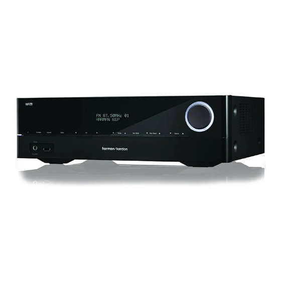
Harman Kardon
Avr 161/230
5.1 CHANNEL 85 Watt per channel A/V RECEIVER
REMOTE CONTROL FUNCTIONS
Released EU2013
CONTENTS
3
EXPLODED VIEW AND PARTS
5
BIAS ADJUSTMENT
7
PARTS LIST
9
SEMICONDUCTOR PINOUTS
10
PCB DRAWINGS
11
12
13
Harman Consumer Group, Inc.
8500 Balboa Boulevard
Northridge, California 91329
Service Manual
14
15
16
50
156
165
166
167
Rev 1.1, 03/2016
Advertisement
Table of Contents

Subscribe to Our Youtube Channel
Related Manuals for Harman Harman/kardon AVR 161


Summary of Contents for Harman Harman/kardon AVR 161
-
Page 1: Service Manual
REAR PANEL CONNECTORS BIAS ADJUSTMENT REMOTE CONTROL FUNCTIONS PARTS LIST PROCESSOR RESET SEMICONDUCTOR PINOUTS TROUBLESHOOTING PCB DRAWINGS SPECIFICATIONS BLOCK DIAGRAMS PACKAGE DRAWING WIRING DIAGRAM DISASSEMBLY SCHEMATIC DIAGRAMS Released EU2013 Harman Consumer Group, Inc. Rev 1.1, 03/2016 8500 Balboa Boulevard Northridge, California 91329... - Page 2 Harman Kardon AVR 161 Service Manual AVR 1710, AVR 171, AVR 171/230C AVR 1610, AVR 161, AVR 161/230C Audio/video receiver Owner’s Manual ® Page 2 of 178...
- Page 3 Harman Kardon AVR 161 Service Manual Front-Panel Controls Front-Panel Controls tuning Mode button (AVr 1710/AVr 1610)/ channel Volume Adjust button button rdS button (AVr 171/ AVr 161) power power Front-panel Volume Indicator button Sensor display knob headphone Jack/ left/right up/down buttons/...
- Page 4 Auto Select, Virtual, Stereo, hArMAn nSp, Movie, Music and Video game. to change the specific surround-sound note: You can use the System Setup menu to set the AVr to automatically enter mode within the category, use the Surround Mode Select buttons.
- Page 5 Harman Kardon AVR 161 Service Manual Rear-Panel Connectors Rear-Panel Connectors AVR 1710/AVR 171 digital Audio connectors Fan Vents radio Antenna network hdMI output hdMI/Mhl Input hdMI Input power cord connectors connector connectors connector connectors (AVr 1710) Subwoofer Speaker Analog Video...
- Page 6 Harman Kardon AVR 161 Service Manual Rear-Panel Connectors Rear-Panel Connectors, continued HDMI Input connectors: An hdMI connection transmits digital audio and video signals ® between devices. If your source devices have hdMI connectors, using them will provide the best possible video and audio performance quality. Since the hdMI cable carries...
- Page 7 Harman Kardon AVR 161 Service Manual System Remote Control Functions System Remote Control Functions Ir transmitter zone 2 button power off button (AVr 1710/AVr 171 only) Mute button power on button Source Selector buttons AVr button Surround Modes button oSd/Menu button...
- Page 8 Surround Modes button: press this button to access the Surround Modes submenu. Select a surround-mode category: Auto Select, Virtual Surround, Stereo, hArMAn nSp, Transport Control buttons: these buttons are used to control source devices. Movie, Music or game. when you select the category, it is highlighted and the surround Previous Channel button: when tV is the selected source, press this button to switch mode changes.
- Page 9 Software Update: If a software upgrade is released for your AVr, installation instructions will be available in the product Support section of the web site or from harman kardon customer service. At that time, you may use this submenu to install the upgrade software.
-
Page 10: Troubleshooting
• A mplifier is in protection mode due to possible short • C heck all speaker wires at speaker and AVR circuit connections for crossed wires • A mplifier is in protection mode due to internal • C ontact your local Harman Kardon service center problems no sound from center or surround speakers • I ncorrect surround mode • S elect a surround mode other than stereo • P rogram material is monophonic • M ono programs contain no surround information • I ncorrect speaker configuration... - Page 11 Harman Kardon AVR 161 Service Manual Specifications Specifications AM Tuner Section Audio Section Frequency range: 520 – 1710khz (AVr 1710/AVr 1610) 522 – 1620khz (AVr 170/AVr 160) Stereo power: AVr 1710/AVr 171: 100w per channel, Signal-to-noise ratio: 38db two channels driven @ 6/8 ohms, 1khz, usable sensitivity (loop): 500µV...
- Page 12 Harman Kardon AVR 161 Service Manual AVR161/230 2. Package Drawing 1. Instruction manual ass'y - Accessories(CQXAVR161/230) MANUAL ASS'Y FM 1 POLE ANT(UL) POLY BAG AM LOOP ANTENNA ASS'Y BATTERY ASS'Y CORD , POWER(EUR) REMOCON MICROPHONE ASS'Y SHEET,QUICK START GUIDE SNOW PAD (L)
- Page 13 Harman Kardon AVR 161 Service Manual DISASSEMBLY AVR161/230 1. Removing the Top Cabinet 3. Removing the Rear Panel Remove the Screws Remove the Screws 18 19 4. Removing the Main PCB Remove the Screws 2. Removing the Front Panel Remove the Screws...
- Page 14 Harman Kardon AVR 161 Service Manual AVR161/230 EXPLODED VIEW 40-5 42-4 42-3 42-2 40-2 REMARK NO DESCRIPTION PARTS NO. Q,ty KNOB,VOLUME CBN1A269B65 40-1 INDICATOR,VOLUME CGL1A300 BADGE, HARMAN/KARDON CGB1A255Z 40-4 WINDOW,FIP CGU2A410A25J BADGE,AVR161 CGB1A260Z FILTER,FIP CMZ1A145 42-1 JACK,COVER CGR1A555B63 KNOB,STANDBY CBT2A1064...
-
Page 15: Bias Adjustment
Harman Kardon AVR 161 Service Manual AMPLIFIER SECTION BIAS ADJUSTMENT Measurement condition .No input signal or volume position is minium. .Do not adjust at FM/AM Standard value .Ideal current = 48mA (±7%) .Ideal DC Voltage = 22.5mA (±7%) DC VOLTMETER ; Connect to... -
Page 16: Parts List
COVER , JACK AVR1510 CGWAVR161/230 FRONT PANEL ASS'Y ...3 CBT2A1064 KNOB , STANDBY ...3 CBT2A1065 KNOB , BACK ...3 CGB1A255Z BADGE , HARMAN/KARDON ...3 CGB1A260Z BADGE , AVR161 ...3 CGL1A265Y INDICATOR , POWER AVR155 ...3 CGR1A538G5 ORNAMENT , RING ...3... - Page 17 Harman Kardon AVR 161 Service Manual Level Ref# Component Description Drawing No ...3 COP12502E AVR1610 FRONT PCB ASS'Y ..6 C911 CCUS1H104KC CAP, CHIP(1608, 50V/0.1uF) ..6 C912 CCUS1H104KC CAP, CHIP(1608, 50V/0.1uF) ..6 C923 CCUS1H681JA CAP, CHIP(1608, 50V/680pF) ..6 C924 CCUS1H681JA CAP, CHIP(1608, 50V/680pF) ..6...
- Page 18 Harman Kardon AVR 161 Service Manual Level Ref# Component Description Drawing No ...3 COP12502E AVR1610 FRONT PCB ASS'Y ..6 R361 CRJ10DJ1R0T RES, CHIP(1608/5%/1ohm) 1608 SIZE ..6 R362 CRJ10DJ1R0T RES, CHIP(1608/5%/1ohm) 1608 SIZE ..6 R363 CRJ10DJ103T RES, CHIP(1608/5%/10Kohm) 00200-0096 ..6 R364 CRJ10DJ4R7T RES, CHIP(1608/5%/4.7ohm)
- Page 19 Harman Kardon AVR 161 Service Manual Level Ref# Component Description Drawing No ...3 COP12502E AVR1610 FRONT PCB ASS'Y ..6 R926 CRJ10DJ104T RES, CHIP(1608/5%/100Kohm) 00200-0097 ..6 R931 CRJ10DJ104T RES, CHIP(1608/5%/100Kohm) 00200-0097 ..6 R932 CRJ10DJ104T RES, CHIP(1608/5%/100Kohm) 00200-0097 ..6 R933 CRJ10DJ221T RES, CHIP(1608/5%/220ohm) 00200-0101 ..6...
- Page 20 Harman Kardon AVR 161 Service Manual Level Ref# Component Description Drawing No ...3 COP12502E AVR1610 FRONT PCB ASS'Y ..4 BN73 CJP06GB142ZB PIN HEADER(6P, 2.54mm) ..4 BN76 CWB1C207380H6001 WIRE ASS'Y (7P,2.0mm,380mm,Shield_ANGLE)_usb ..4 BN78 CWB1B005100HC WIRE ASS'Y Locking (YH) (5P,2MM,100MM,26#) ..4 CN72...
- Page 21 Harman Kardon AVR 161 Service Manual Level Ref# Component Description Drawing No COP12510E AVR1610 BT PCB ASS'Y ..7 C1142 CCEC1CMVG100T CAP,ALUMINUM ELECTROLYTIC (16V/10uF) ..7 IC1100 CNVBM840-AVR161 MODULE, BLUETOOTH SPEC 4.0 ..7 IC1102 CVIPCM5100PWR I.C , 2CH DAC(32BIT,384KHZ,TSSOP-20P) ..7 L1130 CLZ9R005V FERRITE CHIP BEAD(1608/60R, CB03YTYH600) ..7 RN1100...
- Page 22 Harman Kardon AVR 161 Service Manual Level Ref# Component Description Drawing No COP12504F AVR161/230 DIGITAL PCB ASS'Y (EUR) ..7 C1021 CCUI1C104KC CAP, CHIP(1005, 16V/0.1uF) ..7 C1022 CCUS0J475KC CAP, CHIP(1608, 6.3V/4.7uF, MURATA GRM18) GRM188R60J475KE19D ..7 C1023 CCUS0J475KC CAP, CHIP(1608, 6.3V/4.7uF, MURATA GRM18) GRM188R60J475KE19D ..7 C1024...
- Page 23 Harman Kardon AVR 161 Service Manual Level Ref# Component Description Drawing No COP12504F AVR161/230 DIGITAL PCB ASS'Y (EUR) ..7 C1159 CCUS0J225KC CAP, CHIP(1608, 6.3V/2.2uF) ..7 C1162 CCUS1H680JA CAP, CHIP(1608, 50V/68pF) ..7 C1163 CCUS1H103KC CAP, CHIP(1608, 50V/0.01uF) 1608 SIZE ..7 C1164 CCUS1H104KC CAP, CHIP(1608, 50V/0.1uF)
- Page 24 Harman Kardon AVR 161 Service Manual Level Ref# Component Description Drawing No COP12504F AVR161/230 DIGITAL PCB ASS'Y (EUR) ..7 C1374 CCUS1H104KC CAP, CHIP(1608, 50V/0.1uF) ..7 C1375 CCUS1H104KC CAP, CHIP(1608, 50V/0.1uF) ..7 C1377 CCUS1H104KC CAP, CHIP(1608, 50V/0.1uF) ..7 C1378 CCUS1H104KC CAP, CHIP(1608, 50V/0.1uF) ..7 C1379...
- Page 25 Harman Kardon AVR 161 Service Manual Level Ref# Component Description Drawing No COP12504F AVR161/230 DIGITAL PCB ASS'Y (EUR) ..7 L1001 CLZ9R005V FERRITE CHIP BEAD(1608/60R, CB03YTYH600) ..7 L1002 CLZ9R005V FERRITE CHIP BEAD(1608/60R, CB03YTYH600) ..7 L1006 CLZ9R005V FERRITE CHIP BEAD(1608/60R, CB03YTYH600) ..7 L1007...
- Page 26 Harman Kardon AVR 161 Service Manual Level Ref# Component Description Drawing No COP12504F AVR161/230 DIGITAL PCB ASS'Y (EUR) ..7 R1061 CRJ10DJ472T RES, CHIP(1608/5%/4.7Kohm) 00200-0087 ..7 R1062 CRJ10DJ472T RES, CHIP(1608/5%/4.7Kohm) 00200-0087 ..7 R1063 CRJ10DJ472T RES, CHIP(1608/5%/4.7Kohm) 00200-0087 ..7 R1064 CRJ10DJ220T RES, CHIP(1608/5%/22ohm) ..7 R1065...
- Page 27 Harman Kardon AVR 161 Service Manual Level Ref# Component Description Drawing No COP12504F AVR161/230 DIGITAL PCB ASS'Y (EUR) ..7 R1305 CRJ10DJ272T RES, CHIP(1608/5%/2.7Kohm) ..7 R1307 CRJ10DJ272T RES, CHIP(1608/5%/2.7Kohm) ..7 R1309 CRJ10DJ392T RES, CHIP(1608/5%/3.9Kohm) ..7 R1310 CRJ10DJ472T RES, CHIP(1608/5%/4.7Kohm) 00200-0087 ..7 R1311...
- Page 28 Harman Kardon AVR 161 Service Manual Level Ref# Component Description Drawing No COP12504F AVR161/230 DIGITAL PCB ASS'Y (EUR) ..7 R1515 CRJ10DJ152T RES, CHIP(1608/5%/1.5Kohm) 00200-0119 ..7 R1516 CRJ10DJ682T RES, CHIP(1608/5%/6.8Kohm) 1608 SIZE ..7 R1517 CRJ10DJ0R0T RES, CHIP(1608/5%/0ohm) 00200-0090 ..7 R1518 CRJ10DJ332T RES, CHIP(1608/5%/3.3Kohm)
- Page 29 Harman Kardon AVR 161 Service Manual Level Ref# Component Description Drawing No COP12504F AVR161/230 DIGITAL PCB ASS'Y (EUR) ..7 C1112 CCUS1H104KC CAP, CHIP(1608, 50V/0.1uF) ..7 C1113 CCUS1H220JA CAP, CHIP(1608, 50V/22pF) ..7 C1114 CCUS1H220JA CAP, CHIP(1608, 50V/22pF) ..7 C1115 CCUI1C104KC CAP, CHIP(1005, 16V/0.1uF) ..7 C1116...
- Page 30 Harman Kardon AVR 161 Service Manual Level Ref# Component Description Drawing No COP12504F AVR161/230 DIGITAL PCB ASS'Y (EUR) ..7 C1258 CCUS1H104KC CAP, CHIP(1608, 50V/0.1uF) ..7 C1261 CCUC1A226KC CAP, CHIP(2012, 10V/22uF) ..7 C1262 CCUS1H103KC CAP, CHIP(1608, 50V/0.01uF) 1608 SIZE ..7 C1264 CCUS1H103KC CAP, CHIP(1608, 50V/0.01uF)
- Page 31 Harman Kardon AVR 161 Service Manual Level Ref# Component Description Drawing No COP12504F AVR161/230 DIGITAL PCB ASS'Y (EUR) ..7 C1518 CCUS1H391JA CAP, CHIP(1608, 50V/390pF) ..7 C1520 CCUS1H104KC CAP, CHIP(1608, 50V/0.1uF) ..7 C1523 CCEC1CMVG100T CAP,ALUMINUM ELECTROLYTIC (16V/10uF) ..7 C1524 CCUS1H104KC CAP, CHIP(1608, 50V/0.1uF) ..7 C1527...
- Page 32 Harman Kardon AVR 161 Service Manual Level Ref# Component Description Drawing No COP12504F AVR161/230 DIGITAL PCB ASS'Y (EUR) ..7 JK1005 CJJ9H008Y JACK, HDMI(TYPE-A, SMT-19P) ..7 JK1006 CJJ9H008Y JACK, HDMI(TYPE-A, SMT-19P) ..7 JK1100 CJJ9L026Z JACK , RJ-45 With TR (SMT) ..7 L1003...
- Page 33 Harman Kardon AVR 161 Service Manual Level Ref# Component Description Drawing No COP12504F AVR161/230 DIGITAL PCB ASS'Y (EUR) ..7 R1004 CRJ06IJ473T RES, CHIP(1005/5%/47Kohm) RM04JC47K ..7 R1005 CRJ06IJ473T RES, CHIP(1005/5%/47Kohm) RM04JC47K ..7 R1021 CRJ10DJ104T RES, CHIP(1608/5%/100Kohm) 00200-0097 ..7 R1022 CRJ06IJ103T RES, CHIP(1005/5%/10Kohm) RM04JC10K ..7 R1024...
- Page 34 Harman Kardon AVR 161 Service Manual Level Ref# Component Description Drawing No COP12504F AVR161/230 DIGITAL PCB ASS'Y (EUR) ..7 R1144 CRJ10DJ104T RES, CHIP(1608/5%/100Kohm) 00200-0097 ..7 R1146 CRJ10DJ105T RES, CHIP(1608/5%/1Mohm) 00200-0095 ..7 R1148 CRJ10DJ101T RES, CHIP(1608/5%/100ohm) 00200-0100 ..7 R1149 CRJ10DJ105T RES, CHIP(1608/5%/1Mohm) 00200-0095 ..7 R1150...
- Page 35 Harman Kardon AVR 161 Service Manual Level Ref# Component Description Drawing No COP12504F AVR161/230 DIGITAL PCB ASS'Y (EUR) ..7 R1356 CRJ10DJ330T RES, CHIP(1608/5%/33ohm) 00200-0118 ..7 R1357 CRJ10DJ330T RES, CHIP(1608/5%/33ohm) 00200-0118 ..7 R1358 CRJ10DJ103T RES, CHIP(1608/5%/10Kohm) 00200-0096 ..7 R1359 CRJ10DJ330T RES, CHIP(1608/5%/33ohm) 00200-0118 ..7 R1360...
- Page 36 Harman Kardon AVR 161 Service Manual Level Ref# Component Description Drawing No COP12504F AVR161/230 DIGITAL PCB ASS'Y (EUR) ..7 R1477 CRJ10DJ0R0T RES, CHIP(1608/5%/0ohm) 00200-0090 ..7 R1478 CRJ10DJ0R0T RES, CHIP(1608/5%/0ohm) 00200-0090 ..7 R1480 CRJ10DJ103T RES, CHIP(1608/5%/10Kohm) 00200-0096 ..7 R1481 CRJ10DJ103T RES, CHIP(1608/5%/10Kohm) 00200-0096 ..7 R1483...
- Page 37 Harman Kardon AVR 161 Service Manual Level Ref# Component Description Drawing No COP12506F AVR161/230 MAIN PCB ASS'Y ..6 C1750 CCUS1H101JA CAP, CHIP(1608, 50V/100pF) ..6 C1751 CCUS1H101JA CAP, CHIP(1608, 50V/100pF) ..6 C1771 CCUS1H223KC CAP, CHIP(1608, 50V/0.022uF) ..6 C1773 CCUS1H223KC CAP, CHIP(1608, 50V/0.022uF) ..6...
- Page 38 Harman Kardon AVR 161 Service Manual Level Ref# Component Description Drawing No COP12506F AVR161/230 MAIN PCB ASS'Y ..6 R1796 CRJ10DJ473T RES, CHIP(1608/5%/47Kohm) 00200-0185 ..6 R1797 CRJ10DJ392T RES, CHIP(1608/5%/3.9Kohm) ..6 R1798 CRJ10DJ392T RES, CHIP(1608/5%/3.9Kohm) ..6 R1799 CRJ10DJ392T RES, CHIP(1608/5%/3.9Kohm) ..6 R1800...
- Page 39 Harman Kardon AVR 161 Service Manual Level Ref# Component Description Drawing No COP12506F AVR161/230 MAIN PCB ASS'Y ..6 R918 CRJ14CJ473T RES, CHIP(3216/5%/47Kohm) ..6 R919 CRJ14CJ473T RES, CHIP(3216/5%/47Kohm) ..6 R920 CRJ14CJ473T RES, CHIP(3216/5%/47Kohm) ..6 R925 CRJ10DJ103T RES, CHIP(1608/5%/10Kohm) 00200-0096 ..6 R928...
- Page 40 Harman Kardon AVR 161 Service Manual Level Ref# Component Description Drawing No COP12506F AVR161/230 MAIN PCB ASS'Y ..5 C815 CCKT1H331KB CAP, CERAMIC(50V/330pF/K) CKB 1H 331K 04 FK5 ..5 C817 CCEA2AH100T CAP, ELECT(100V/10uF) ..5 C819 CCBS1H271KBT CAP , CERAMIC(270PF/50V) CH UP025 B271K-A-B Z ..5...
- Page 41 Harman Kardon AVR 161 Service Manual Level Ref# Component Description Drawing No COP12506F AVR161/230 MAIN PCB ASS'Y ..5 Q820 CVTKSC1845FTA NPN, TO-92, LOW NOISE, HFE:300-600, FAILCHILD KSC1845FTA ..5 Q961 HVTKTA1024YT KTA1024-Y-AT/P ..5 R501 CRD20TJ433T RES, CARBON(1/5W,43Kohm,J) 43K OHM 1/5W J ..5...
- Page 42 Harman Kardon AVR 161 Service Manual Level Ref# Component Description Drawing No COP12506F AVR161/230 MAIN PCB ASS'Y ..5 R594 CRD20TJ561T RES, CARBON(1/5W,560ohm,J) ..5 R596 CRD20TJ561T RES, CARBON(1/5W,560ohm,J) ..5 R597 CRD20TJ561T RES, CARBON(1/5W,560ohm,J) ..5 R598 CRD20TJ561T RES, CARBON(1/5W,560ohm,J) ..5 R599 CRD20TJ561T RES, CARBON(1/5W,560ohm,J) ..5...
- Page 43 Harman Kardon AVR 161 Service Manual Level Ref# Component Description Drawing No COP12506F AVR161/230 MAIN PCB ASS'Y ..5 R726 CRG2SANJR47RT RES, M-OXIDE FILM(2W/0.47ohm) ..5 R727 CRG2SANJR47RT RES, M-OXIDE FILM(2W/0.47ohm) ..5 R728 CRG2SANJR47RT RES, M-OXIDE FILM(2W/0.47ohm) ..5 R729 CRG2SANJR47RT RES, M-OXIDE FILM(2W/0.47ohm) ..5...
- Page 44 Harman Kardon AVR 161 Service Manual Level Ref# Component Description Drawing No COP12506F AVR161/230 MAIN PCB ASS'Y ..5 R954 CRD20TJ102T RES, CARBON(1/5W,1Kohm,J) ..5 R955 CRD20TJ564T RES, CARBON(1/5W,560Kohm,J) ..5 R961 CRD20TJ331T RES, CARBON(1/5W,330ohm,J) ..5 R962 CRD20TJ273T RES, CARBON(1/5W,27Kohm,J) ..5 R990 CRG1SANJ100RT RES, M-OXIDE FILM(1W/10ohm) ..5...
- Page 45 Harman Kardon AVR 161 Service Manual Level Ref# Component Description Drawing No COP12506F AVR161/230 MAIN PCB ASS'Y ..4 Q882 HVTKTC3423Y T.R , PRE DRIVE KTC3423-Y-U/PH ..4 Q883 HVTKTC3423Y T.R , PRE DRIVE KTC3423-Y-U/PH ..4 Q884 HVTKTC3423Y T.R , PRE DRIVE KTC3423-Y-U/PH ..4...
- Page 46 Harman Kardon AVR 161 Service Manual Level Ref# Component Description Drawing No ...3 COP12509F AVR161/230 SMPS PCB ASS'Y ..6 D917 CVDMM1Z16H DIODE , ZENER(16V/0.5W, SOD-123) ..6 D918 CVDMM1Z16H DIODE , ZENER(16V/0.5W, SOD-123) ..6 D922 CVD1N4448W DIODE , FAST SWITCHING(0.5W, SOD-123) ..6...
- Page 47 Harman Kardon AVR 161 Service Manual Level Ref# Component Description Drawing No ...3 COP12509F AVR161/230 SMPS PCB ASS'Y ..6 R954 CRJ18AJ472T RES, CHIP(2012/5%/4.7Kohm) 0805 5% ..6 R955 CRJ14CF5602T RES, CHIP(3216/1%/56Kohm) ..6 R956 CRJ18AJ473T RES, CHIP(2012/5%/47Kohm) 0805 5% ..6 R957 CRJ18AJ181T...
- Page 48 Harman Kardon AVR 161 Service Manual Level Ref# Component Description Drawing No ...3 COP12509F AVR161/230 SMPS PCB ASS'Y ..5 ET95 CJT1A026 PLATE , EARTH(TRONIC ELECTRONICS) ..5 FH91 KJCFC5S HOLDER , FUSE ..5 FH92 KJCFC5S HOLDER , FUSE ..5 IC99 CVIL78L24AB...
- Page 49 Harman Kardon AVR 161 Service Manual Level Ref# Component Description Drawing No ...3 COP12509F AVR161/230 SMPS PCB ASS'Y ..4 L924 CLZ9Z090Z COIL , CHOKE(7UH) ..4 L925 CLZ9Z090Z COIL , CHOKE(7UH) ..4 L928 CLZ9Z090Z COIL , CHOKE(7UH) ..4 PC91 CVIEL817B I.C , PHOTO COUPLER EL817B ..4...
- Page 50 Harman Kardon AVR 161 Service Manual HOMI(HK) COMPANY LTD. Specifications for Approval of 15 Page 50 of 178...
- Page 51 Harman Kardon AVR 161 Service Manual Page 51 of 178...
- Page 52 Harman Kardon AVR 161 Service Manual Page 52 of 178...
- Page 53 Harman Kardon AVR 161 Service Manual Page 53 of 178...
- Page 54 Harman Kardon AVR 161 Service Manual SEMICONDUCTOR KTC3423 TECHNICAL DATA TRIPLE DIFFUSED NPN TRANSISTOR AUDIO FREQUENCY AMPLIFIER APPLICATION. FEATURES High Breakdown Voltage : V =150V(Min.). Low Output Capacitance : C =5.0pF(Max.). High Transition Frequency : f =120MHz(Typ.). Complementary to KTA1360.
- Page 55 Harman Kardon AVR 161 Service Manual KTC3423 COMMON EMITTER COMMON EMITTER Ta=25 C Ta=25 C =10V I =50µA COLLECTOR-EMITTER VOLTAGE V COLLECTOR CURRENT I (mA) CE(sat) COMMON COMMON EMITTER EMITTER Ta=25 C Ta=100 C Ta=25 C Ta=0 C 0.05 COLLECTOR CURRENT I...
- Page 56 Harman Kardon AVR 161 Service Manual KTC3423 C , C - V f=1MHz COMMON EMITTER Ta=25 C Ta=25 C =30V =10V REVERSE VOLTAGE V (V) COLLECTOR CURRENT I (mA) SAFE OPERATING AREA SINGLE NONREPETITIVE PULSE Pc - Ta Ta=25 C I MAX.
-
Page 57: Technical Data
Harman Kardon AVR 161 Service Manual SEMICONDUCTOR KTC812T TECHNICAL DATA EPITAXIAL PLANAR NPN TRANSISTOR FOR MUTING AND SWITCHING APPLICATION. FEATURES High Emitter-Base Voltage : V =25V(Min.) DIM MILLIMETERS High Reverse h 2.9 0.2 : Reverse h =150(Typ.) (V =-2V, I =-4mA) 1.6+0.2/-0.1... - Page 58 Harman Kardon AVR 161 Service Manual SEMICONDUCTOR KTA1360 TECHNICAL DATA TRIPLE DIFFUSED PNP TRANSISTOR AUDIO FREQUENCY AMPLIFIER APPLICATION. FEATURES High Voltage : V =-150V. Low Output Capacitance : C =5.0pF(Max.). High Transition Frequency : f =120MHz(Typ.) Complementary to KTC3423. MILLIMETERS 8.3 MAX...
- Page 59 Harman Kardon AVR 161 Service Manual KTA1360 COMMON COMMON EMITTER EMITTER Ta=25 C Ta=25 C -300µA =-10V -200µA I =-100µA -0.5 -100 COLLECTOR-EMITTER VOLTAGE V COLLECTOR CURRENT I (mA) CE(sat) COMMON EMITTER COMMON EMITTER Ta=25 C =-5V Ta=100 C Ta=25 C Ta=-25 C -0.5...
- Page 60 Harman Kardon AVR 161 Service Manual KTA1360 Pc - Ta SAFE OPERATING AREA -300 MAX(PULSE) -100 MAX(CONTINUOUS) SINGLE NONREPETITIVE PULSE Ta=25 C CURVES MUST BE DERATED LINEARLY WITH INCREASE IN TEMPERATURE -100 -300 AMBIENT TEMPERATURE Ta ( C) COLLECTOR-EMITTER VOLTAGE V 2003.
- Page 61 Harman Kardon AVR 161 Service Manual Page 61 of 178...
- Page 62 Harman Kardon AVR 161 Service Manual Page 62 of 178...
- Page 63 Harman Kardon AVR 161 Service Manual Page 63 of 178...
- Page 64 Harman Kardon AVR 161 Service Manual KSC1845 Audio Frequency Low Noise Amplifier • Complement to KSA992 TO-92 1. Emitter 2. Collector 3. Base NPN Epitaxial Silicon Transistor Absolute Maximum Ratings =25°C unless otherwise noted Symbol Parameter Value Units Collector-Base Voltage...
- Page 65 Harman Kardon AVR 161 Service Manual Typical Characteristics µ µ =1.4 µ =1.2 µ =1.0 µ µ µ =0.8 µ µ =0.6 µ µ =0.4 µ µ µ =0.2 µ [V], COLLECTOR-EMITTER VOLTAGE [V], COLLECTOR-EMITTER VOLTAGE Figure 1. Static Characteristic Figure 2.
- Page 66 Harman Kardon AVR 161 Service Manual Typical Characteristics (Continued) = 6V Pulse Test 0.01 [V], BASE-EMITTER VOLTAGE C], CASE TEMPERATURE Figure 7. Collector Current vs. Base-Emitter Voltage Figure 8. Power Derating ©2002 Fairchild Semiconductor Corporation Rev. B2, November 2002 Page 66 of 178...
- Page 67 Harman Kardon AVR 161 Service Manual APPROVED July-14-2008 Page 67 of 178...
-
Page 68: Absolute Maximum Ratings
Harman Kardon AVR 161 Service Manual KSA992 Audio Frequency Low Noise Amplifier • Complement to KSC1845 TO-92 1. Emitter 2. Collector 3. Base PNP Epitaxial Silicon Transistor Absolute Maximum Ratings =25°C unless otherwise noted Symbol Parameter Ratings Units Collector-Base Voltage... - Page 69 Harman Kardon AVR 161 Service Manual Typical Characteristics -1.0 = -1.2 µ = -24 µ = -1.2 µ = -20 µ = -1.0 µ -0.8 = -16 µ = -0.8 µ -0.6 = -12 µ = -0.6 µ = -8 µ...
- Page 70 Harman Kardon AVR 161 Service Manual Typical Characteristics (Continued) C], AMBIENT TEMPERATURE Figure 7. Power Derating ©2004 Fairchild Semiconductor Corporation Rev. B2, August 2004 Page 70 of 178...
- Page 71 Harman Kardon AVR 161 Service Manual APPROVED July-14-2008 Page 71 of 178...
- Page 72 Harman Kardon AVR 161 Service Manual ISAHAYA ELECTRONICS CORPORATION Page 72 of 178...
- Page 73 Harman Kardon AVR 161 Service Manual ISAHAYA ELECTRONICS CORPORATION Page 73 of 178...
- Page 74 Harman Kardon AVR 161 Service Manual ISAHAYA ELECTRONICS CORPORATION Page 74 of 178...
- Page 75 Harman Kardon AVR 161 Service Manual Page 75 of 178...
- Page 76 Harman Kardon AVR 161 Service Manual Page 76 of 178...
- Page 77 Harman Kardon AVR 161 Service Manual Page 77 of 178...
- Page 78 Harman Kardon AVR 161 Service Manual ISAHAYA ELECTRONICS CORPORATION Page 78 of 178...
- Page 79 Harman Kardon AVR 161 Service Manual ISAHAYA ELECTRONICS CORPORATION Page 79 of 178...
- Page 80 Harman Kardon AVR 161 Service Manual 〈 Transistor〉 R T 1 N 1 4 4 X SERIES Transistor With Resistor For Switching Application Silicon NPN Epitaxial Type DESCRIPTION OUTLINE DRAWING UNIT: mm RT1N144X is a one chip transistor RT1N144U RT1N144C with built-in bias resistor,PNP type is RT1P144X.
- Page 81 Harman Kardon AVR 161 Service Manual 〈 Transistor〉 R T 1 N 1 4 4 X SERIES Transistor With Resistor For Switching Application Silicon NPN Epitaxial Type MAXIMUM RATING (Ta=25℃) RATING SYMBOL PARAMETER UNIT RT1N144T2 RT1N144U RT1N144M RT1N144C RT1N144S V...
- Page 82 Harman Kardon AVR 161 Service Manual 〈 Transistor〉 R T 1 N 1 4 4 X SERIES Transistor With Resistor For Switching Application Silicon NPN Epitaxial Type DC FORWARD CURRENT GAIN COMMON EMITTER OUTPUT VS COLLECTOR CURRENT 1000 VCE=5V IB=0.10mA Ta=25℃...
- Page 83 Harman Kardon AVR 161 Service Manual HOMI(HK) COMPANY LTD. Specifications for Approval of 15 Page 83 of 178...
- Page 84 Harman Kardon AVR 161 Service Manual LM7900 Imagis Co., Ltd. 1. Overview Description LM7900 series of fixed output negative voltage regulators are intended as complement to LM7800 series devices. These negative regulators are available in the same even-voltage options as the LM7800 devices Features •...
- Page 85 Harman Kardon AVR 161 Service Manual LM7800 Imagis Co., Ltd. 1. Overview Description The voltage regulators are designed as fixed-voltage regulator for a wide variety of applications Including local,on-card regulation. Although designed primarily as a fixed voltage regulator, these devices can be used with external components to obtain adjustable voltages and currents Features •...
- Page 86 Harman Kardon AVR 161 Service Manual Page 86 of 178...
- Page 87 Harman Kardon AVR 161 Service Manual Page 87 of 178...
- Page 88 Harman Kardon AVR 161 Service Manual Page 88 of 178...
- Page 89 Harman Kardon AVR 161 Service Manual Page 89 of 178...
- Page 90 Harman Kardon AVR 161 Service Manual Page 90 of 178...
- Page 91 Harman Kardon AVR 161 Service Manual Page 91 of 178...
- Page 92 Harman Kardon AVR 161 Service Manual ESMT/EMP EML3418 1.3MHz 2A, Synchronous Step-Down Regulator General Description Features EML3418 is designed with high efficiency step Achieve 95% efficiency down DC/DC converter for portable devices Input Voltage : 2.5V to 5.5V applications. It features with extreme low...
- Page 93 Harman Kardon AVR 161 Service Manual ESMT/EMP EML3418 Connection Diagram Order information TDFN-8 Package EML3418-00FF08NRR Adj Operation FF08 TDFN-8 Package RoHS & Halogen Free Rating: -40 to 85°C Package in Tape & Reel EML3418-00SE08GRR/NRR SOP-8FD Package Adj Operation SE08 SOP-8FD package RoHS (Pb Free) Rating: -40 to 85°C...
- Page 94 Harman Kardon AVR 161 Service Manual ESMT/EMP EML3418 Package Configuration SOP-8 Adjustable Pin Functions Pin # Pin Name Function Feedback Pin. Receives the feedback voltage from an external (Adjustable) resistive divider across the output. Output Voltage Pin. An internal resistive divider divides the output (Fixed voltage down for comparison to the internal reference voltage.
- Page 95 Harman Kardon AVR 161 Service Manual DB1514A 1.5A, Low Dropout Regulator with Power Good DESCRIPTION FEATURES The DB1514A is a very low dropout voltage linear Input Voltage Range: 2.5V to 6.0V regulator which can operate from the input Low Quiescent Current: Typ. 300uA @ voltages as low as 2.5V and is capable of...
- Page 96 Harman Kardon AVR 161 Service Manual DB1514A PIN DESCRIPTION PIN NO SYMBOL DESCRIPTION 8-TDFN 8-SOP-EP Open Drain Power-Good (PG) Output. Enable Input. Input Supply Voltage Pin. Output pin Feedback Pin. Connect to output through a voltage-divider to set the output. Recommended that the tolerance of feedback resistors is below 1%.
- Page 97 Harman Kardon AVR 161 Service Manual DB1230 3A, 700KHz, Synchronous Step-down Converter DESCRIPTION FEATURES The DB1230 is a high frequency synchronous 4.5V to 16V operating input range. rectified step-down regulator which integrates an High-side 110 mΩ, low-side 85 mΩ 110mΩ high-side power MOSFET and an 85mΩ...
- Page 98 Harman Kardon AVR 161 Service Manual DB1230 PIN DESCRIPTION PIN NO. SYMBOL DESCRIPTION Enable pin. For automatic start-up, please leave it open and in case of on/off control, there should be pull-down resistor.(10K~100Kohm) Feedback pin. External resistors are connected between OUT and GND to set the regulated output voltage based on 0.8V reference.
- Page 99 Harman Kardon AVR 161 Service Manual DB1510B 1A, 0.8V Dropout LDO Regulator DESCRIPTION FEATURES DB1510B low-dropout linear regulator Input Voltage Range: 2.2V to 6.0V operates from input voltages as low as 2.2V and Quiescent Current: Typ. 400uA are able to deliver up to 1A of continuous output Current limit : Min.
- Page 100 Harman Kardon AVR 161 Service Manual DB1510B PIN DESCRIPTION PIN NO SYMBOL DESCRIPTION TO-252 (I) TO-252 (II) 8-TDFN SOT-223 (I) SOT-223 (II) Input Voltage 2, TAB Ground 2, TAB 5, 6 Output Voltage 2, 4, 7, 8 No Connection PIN CONFIGURATION...
- Page 101 Harman Kardon AVR 161 Service Manual Page 101 of 178...
- Page 102 Harman Kardon AVR 161 Service Manual Page 102 of 178...
- Page 103 Harman Kardon AVR 161 Service Manual Page 103 of 178...
- Page 104 Harman Kardon AVR 161 Service Manual Page 104 of 178...
- Page 105 Harman Kardon AVR 161 Service Manual Page 105 of 178...
- Page 106 Harman Kardon AVR 161 Service Manual Page 106 of 178...
- Page 107 Harman Kardon AVR 161 Service Manual Page 107 of 178...
-
Page 108: Product Description
Harman Kardon AVR 161 Service Manual ® Product Specification BM840 Stereo Solution Module Features: Qualified Bluetooth Spec 4.0 Compliant Class 2 type Output Power Support A2DP 1.2,AVRCP V1.4,HSP 1.2 and HFP 1.6 Profiles April 2012 Secure simple pairing, CSR's proximity pairing and CSR's proximity connection HFP v1.6 includes wideband speech and mSBC... -
Page 109: Product Specification
Harman Kardon AVR 161 Service Manual ® Product Specification Pin Configurations Ground Ground AIO0 Bi-directional Analogue programmable input / output line PIO12 Bi-directional Programmable Input/Output Line Alternative function: ■ QSPI_FLASH_CS#: serial quad I/O flash chip select ■ I2C_WP: I²C bus memory write protect line... - Page 110 Harman Kardon AVR 161 Service Manual ® Product Specification Typically connected to VBUS (USB supply) as Section 12 shows. CHG_EXT External battery charger control. External battery charger transistor base control when using external charger boost. Otherwise leave unconnected. VBAT_SENSE Battery charger sense input.
- Page 111 Harman Kardon AVR 161 Service Manual ® Product Specification Recommended Layout patterns: Spec-BM840-V1.1 Page 5 of 7 www.sunitec.com.tw Page 111 of 178...
-
Page 112: General Description
Harman Kardon AVR 161 Service Manual Data Sheet 600mA LOW DROPOUT LINEAR REGULATOR 600mA LOW DROPOUT LINEAR REGULATOR AP1117M AP2317 LOW DROPOUT LINEAR REGULATOR AZ1117C General Description Features The AZ1117C is a low dropout three-terminal regula- · Current Limit: 1.0A (Typ.) tor. - Page 113 Harman Kardon AVR 161 Service Manual Data Sheet 600mA LOW DROPOUT LINEAR REGULATOR 600mA LOW DROPOUT LINEAR REGULATOR AP1117M AP2317 LOW DROPOUT LINEAR REGULATOR AZ1117C Pin Configuration D Package (TO-252-2 (2)) (TO-252-2 (1)) INPUT INPUT OUTPUT OUTPUT ADJ/GND ADJ/GND (TO-252-2 (3))
- Page 114 Harman Kardon AVR 161 Service Manual Description The Atmel AT45DB321D is a 2.5V or 2.7V, serial interface, sequential access flash memory ideally suited for a wide variety of digital voice-, image-, program code-, and data-storage applications. The AT45DB321D supports the Atmel RapidS serial interface for applications requiring very high speed operations.
- Page 115 Harman Kardon AVR 161 Service Manual Table 1-1. Pin Configurations Asserted Symbol Name and Function State Type Input Chip Select: Asserting the CS pin selects the device. When the CS pin is deasserted, the device will be deselected and normally be placed in the standby mode (not deep power- down mode), and the output pin (SO) will be in a high-impedance state.
- Page 116 Harman Kardon AVR 161 Service Manual 128M Single Data Rate Synchronous DRAM PIN CONFIGURATION (TOP VIEW) DQ15 VddQ VddQ VssQ VssQ DQ14 DQ13 VssQ VssQ VddQ VddQ DQ12 DQ11 VddQ VddQ VssQ VssQ DQ10 VssQ VssQ VddQ VddQ DQML DQMU...
- Page 117 Harman Kardon AVR 161 Service Manual 128M Single Data Rate Synchronous DRAM Clock: CLK is driven by the system clock. All SDRAM input signals are sampled on the positive edge of CLK. CLK also increments the internal burst counter and controls the output registers.
- Page 118 Harman Kardon AVR 161 Service Manual 2N7002K SEMICONDUCTOR N Channel MOSFET TECHNICAL DATA ESD Protected 2000V INTERFACE AND SWITCHING APPLICATION. FEATURES ESD Protected 2000V. MILLIMETERS High density cell design for low R DS(ON) 2.93 0.20 Voltage controlled small signal switch.
- Page 119 Harman Kardon AVR 161 Service Manual DATA SHEET MOS FIELD EFFECT TRANSISTOR µ PA672T N-CHANNEL MOS FET ARRAY FOR SWITCHING The µ PA672T is a super-mini-mold device provided PACKAGE DIMENSIONS (in millimeters) with two MOS FET elements. It achieves high-density +0.1...
- Page 120 Harman Kardon AVR 161 Service Manual Page 120 of 178...
- Page 121 Harman Kardon AVR 161 Service Manual Page 121 of 178...
- Page 122 Harman Kardon AVR 161 Service Manual Page 122 of 178...
- Page 123 Harman Kardon AVR 161 Service Manual Page 123 of 178...
- Page 124 Harman Kardon AVR 161 Service Manual Page 124 of 178...
- Page 125 Harman Kardon AVR 161 Service Manual STM32F205xx, STM32F207xx Pinouts and pin description Pinouts and pin description Figure 9. STM32F20x LQFP64 pinout 64 63 62 61 60 59 58 57 56 55 54 53 52 51 50 49 17 18 19 20 21 22 23 24...
- Page 126 Harman Kardon AVR 161 Service Manual Pinouts and pin description STM32F205xx, STM32F207xx Figure 11. STM32F20x LQFP100 pinout 1. RFU means “reserved for future use”. 34/147 Doc ID 15818 Rev 5 Page 126 of 178...
- Page 127 Harman Kardon AVR 161 Service Manual STM32F205xx, STM32F207xx Pinouts and pin description Figure 12. STM32F20x LQFP144 pinout 1. RFU means “reserved for future use”. Doc ID 15818 Rev 5 35/147 Page 127 of 178...
- Page 128 Harman Kardon AVR 161 Service Manual Pinouts and pin description STM32F205xx, STM32F207xx Figure 13. STM32F20x LQFP176 pinout 1. Package not in production and available for development only. 2. RFU means “reserved for future use”. 36/147 Doc ID 15818 Rev 5...
- Page 129 Harman Kardon AVR 161 Service Manual STM32F205xx, STM32F207xx Pinouts and pin description Figure 14. STM32F21xxx UFBGA176 ballout PG14 PG13 PC12 PA15 PA14 PA13 PG15 PG12 PG11 PG10 PC11 PC10 PA12 VDD_3 VBAT VDD_11 VDD_10 VDD_15 PA11 PC13- PI8- BOOT0 VSS_11...
- Page 130 Harman Kardon AVR 161 Service Manual Pinouts and pin description STM32F205xx, STM32F207xx Table 5. STM32F20x pin and ball definitions Pins Main Other Pin name function Alternate functions functions (after reset) TRACECLK/ FSMC_A23 / I/O FT ETH_MII_TXD3 I/O FT TRACED0/FSMC_A19 TRACED1/FSMC_A20 /...
- Page 131 Harman Kardon AVR 161 Service Manual STM32F205xx, STM32F207xx Pinouts and pin description Table 5. STM32F20x pin and ball definitions (continued) Pins Main Other Pin name function Alternate functions functions (after reset) 22 28 PF10 I/O FT PF10 FSMC_INTR ADC3_IN8 E9 12 23 29 G1...
- Page 132 Harman Kardon AVR 161 Service Manual Pinouts and pin description STM32F205xx, STM32F207xx Table 5. STM32F20x pin and ball definitions (continued) Pins Main Other Pin name function Alternate functions functions (after reset) USART2_RX/TIM5_CH4 / TIM9_CH2 / TIM2_CH4 / 17 G7 26 37 47 R2...
- Page 133 Harman Kardon AVR 161 Service Manual STM32F205xx, STM32F207xx Pinouts and pin description Table 5. STM32F20x pin and ball definitions (continued) Pins Main Other Pin name function Alternate functions functions (after reset) 51 61 M8 SS_6 SS_6 52 62 N8 DD_6...
- Page 134 Harman Kardon AVR 161 Service Manual Pinouts and pin description STM32F205xx, STM32F207xx Table 5. STM32F20x pin and ball definitions (continued) Pins Main Other Pin name function Alternate functions functions (after reset) I2C3_SMBA / TIM12_CH2/ 86 M13 I/O FT DCMI_D0 TIM5_CH1_ETR /...
- Page 135 Harman Kardon AVR 161 Service Manual STM32F205xx, STM32F207xx Pinouts and pin description Table 5. STM32F20x pin and ball definitions (continued) Pins Main Other Pin name function Alternate functions functions (after reset) 61 85 104 M14 PD14 I/O FT PD14 FSMC_D0/TIM4_CH3...
- Page 136 Harman Kardon AVR 161 Service Manual Pinouts and pin description STM32F205xx, STM32F207xx Table 5. STM32F20x pin and ball definitions (continued) Pins Main Other Pin name function Alternate functions functions (after reset) USART1_RTS / CAN1_TX/ 45 C1 71 104 123 B15...
- Page 137 Harman Kardon AVR 161 Service Manual STM32F205xx, STM32F207xx Pinouts and pin description Table 5. STM32F20x pin and ball definitions (continued) Pins Main Other Pin name function Alternate functions functions (after reset) TIM3_ETR/UART5_RX 54 C7 83 116 144 D12 I/O FT...
- Page 138 Harman Kardon AVR 161 Service Manual Pinouts and pin description STM32F205xx, STM32F207xx Table 5. STM32F20x pin and ball definitions (continued) Pins Main Other Pin name function Alternate functions functions (after reset) I2C1_SMBA/ CAN2_RX / OTG_HS_ULPI_D7 / 57 A5 91 135 163 A6...
- Page 139 Harman Kardon AVR 161 Service Manual SiI9573 and SiI9575 Port Processor Advance Data Sheet Silicon Image, Inc. Pin Diagram Pin diagram is subject to change. Figure 2 shows the pin assignments of the SiI957n port processor. The Target Pin Descriptions section describing the pin functions begins on page 16.
-
Page 140: Device Information
Harman Kardon AVR 161 Service Manual PCM5100, PCM5101, PCM5102 SLAS764 – MAY 2011 www.ti.com DEVICE INFORMATION TERMINAL FUNCTIONS, PCM510x PCM510X (top view) Table 2. TERMINAL FUNCTIONS, PCM510x TERMINAL DESCRIPTION NAME CPVDD Charge pump power supply, 3.3V CAPP Charge pump flying capacitor terminal for positive rail... - Page 141 Harman Kardon AVR 161 Service Manual tenatative NJM8080 DUAL OPERATIONAL AMPLIFIER ■ GENERAL DESCRIPTION ■ PACKAGE OUTLINE NJM8080 is the dual operational amplifier, specially designed for improving the tone control, which is most suitable for the audio application. Featuring noiseless, higher gain bandwidth, high output current and...
- Page 142 Harman Kardon AVR 161 Service Manual Page 142 of 178...
- Page 143 Harman Kardon AVR 161 Service Manual MX25L8006E MX25L1606E PIN CONFIGURATIONS 16-PIN SOP (300mil) for MX25L1606E only 8-PIN SOP (200mil, 150mil) HOLD# SCLK SI/SIO0 SO/SIO1 HOLD# SCLK SI/SIO0 SO/SIO1 8-PIN PDIP (300mil) 8-LAND WSON (6x5mm), USON (4x4mm) SO/SIO1 HOLD# HOLD# SO/SIO1...
- Page 144 Harman Kardon AVR 161 Service Manual Page 144 of 178...
- Page 145 Harman Kardon AVR 161 Service Manual Page 145 of 178...
- Page 146 Harman Kardon AVR 161 Service Manual M24C64-W M24C64-R M24C64-F M24C32-W M24C32-R M24C32-F 64 Kbit and 32 Kbit Serial I²C bus EEPROM Feature summary Two-Wire I C serial interface Supports 400kHz Protocol Single supply voltage: – 2.5 to 5.5V for M24Cxx-W –...
-
Page 147: List Of Figures
Harman Kardon AVR 161 Service Manual M24Cxx-W, M24Cxx-R, M24Cxx-F List of figures List of figures Figure 1. Logic diagram ............6 Figure 2. - Page 148 Harman Kardon AVR 161 Service Manual Summary description M24Cxx-W, M24Cxx-R, M24Cxx-F Summary description These I C-compatible electrically erasable programmable memory (EEPROM) devices are organized as 8192 × 8 bits (M24C64-x) and 4096 × 8 bits (M24C32-x). Figure 1. Logic diagram...
- Page 149 Harman Kardon AVR 161 Service Manual M24Cxx-W, M24Cxx-R, M24Cxx-F Summary description Figure 2. DIP, SO, TSSOP and UFDFPN connections M24C64-x M24C32-x V CC V SS AI01845d 1. See Package mechanical section for package dimensions, and how to identify pin-1. 7/34...
- Page 150 Harman Kardon AVR 161 Service Manual Signal description M24Cxx-W, M24Cxx-R, M24Cxx-F Signal description 2.0.1 Serial Clock (SCL) This input signal is used to strobe all data in and out of the device. In applications where this signal is used by slave devices to synchronize the bus to a slower clock, the bus master...
- Page 151 Harman Kardon AVR 161 Service Manual M24Cxx-W, M24Cxx-R, M24Cxx-F Signal description Supply voltage (V 2.3.1 Operating supply voltage V Prior to selecting the memory and issuing instructions to it, a valid and stable V voltage within the specified [V (min), V...
- Page 152 Harman Kardon AVR 161 Service Manual Signal description M24Cxx-W, M24Cxx-R, M24Cxx-F Figure 5. C bus protocol START STOP Input Change Condition Condition START Condition STOP Condition AI00792B Table 2. Device select code Device Type Identifier Chip Enable Address Device Select Code 1.
- Page 153 Harman Kardon AVR 161 Service Manual ESMT M12L16161A (2Q) (Preliminary) SDRAM 512K x 16Bit x 2Banks Synchronous DRAM FEATURES GENERAL DESCRIPTION The M12L16161A is 16,777,216 bits synchronous high data JEDEC standard 3.3V power supply rate Dynamic RAM organized as 2 x 524,288 words by 16 bits,...
- Page 154 Harman Kardon AVR 161 Service Manual Page 154 of 178...
- Page 155 Harman Kardon AVR 161 Service Manual Page 155 of 178...
- Page 156 Harman Kardon AVR 161 Service Manual Page 156 of 178...
- Page 157 Harman Kardon AVR 161 Service Manual Page 157 of 178...
- Page 158 Harman Kardon AVR 161 Service Manual Page 158 of 178...
- Page 159 Harman Kardon AVR 161 Service Manual Page 159 of 178...
- Page 160 Harman Kardon AVR 161 Service Manual Page 160 of 178...
- Page 161 Harman Kardon AVR 161 Service Manual Page 161 of 178...
- Page 162 Harman Kardon AVR 161 Service Manual Page 162 of 178...
- Page 163 Harman Kardon AVR 161 Service Manual Page 163 of 178...
- Page 164 Harman Kardon AVR 161 Service Manual AVR161 Block Diagram AVR161 Block Diagram To HDMI / Milan/BT SPDIF & Analog Audio I2S I/F By Upgrade UART UART & GPIO DAI 1 DA0 2 CS49834 CS49834 UART GPIO DAI 2 DSP Controls Main MCU Main MCU IR In X 1 STM32F205ZFT6 STM32F205ZFT6 Trigger out I2S Out GPIO GPIO Optical In CS42528 CS42528 X 1...
-
Page 165: Block Diagrams
Harman Kardon AVR 161 Service Manual AVR161 Block Diagram AVR161 Block Diagram HDMI/MHL 1 HDMI O t HDMI Out SII9573 SII9573 HDMI 2/3/4/5 HDMI HDMI Repeater Repeater BT Module BT Module BT BM840 BM840 BlueTooth AZ4580 AZ4580 Antenna Audio Out Audio Out Ethernet RJ‐45... -
Page 166: Wiring Diagram
Harman Kardon AVR 161 Service Manual WIRING DIAGRAM AC IN POWER CORD TYPE DIGITAL B'D 230V : IEC Removable CN1100 F-USB REAR PANEL WF1401 WF1500 WF1400 1.25mm pitch 1.0mm pitch 1.25mm pitch 3.96mm Pitch CN90 JACK B'D SMPS B'd WF31 1.25mm pitch... -
Page 167: Schematic Diagrams
Harman Kardon AVR 161 Service Manual MHL PORT +3.3V_TX AVDD33 XTAL_VCC33 +1.3V_TX AVDD13 R1006 OPEN EN_RX1_PWR VOUT TDVDD13 APVCC13 L1003 L1005 L1006 R1017 L1002 R1007 0_NC L1008 ST+5V_HDMI HCB1608KF-600T30 HCB1608KF-600T30 L1010 HCB1608KF-600T30 HCB1608KF-600T30 HCB1608KF-600T30 OPEN R1018 HCB1608KF-600T30 +5VH1 R1019 IC1001... - Page 168 Harman Kardon AVR 161 Service Manual USB Switch Part AVR161/230 NET_3.3V NET_3.3V USB_ OE L1112 L1113 USB_SEL MCU_USB_DM NET_3.3V MCU_USB_DP CHGND CHGND R1100 L1111 CHGND CHGND C1100 NET_1.2V 10V/22uF C1101 CHGND CHGND L1110 L1114 0.01uF NET_3.3V IC1100 NET_3.3V CVIISL54220IUZ-T L1109 NET_1.2V...
- Page 169 Harman Kardon AVR 161 Service Manual 2012.03.01 L1201 R1212 FROM SMPS R1208 CLZ9Z014Z R1209 R1213 L1202 R1210 CLZ9Z014Z R1211 R1214 L1203 R1265 PW_GND AGND CLZ9Z014Z R1215 POWER_DOWN POWER_DOWN C1212 +5V_DC/DC DC/DC (DSP +1.0V) AMP_VCC_ON AMP_VCC_CONT ST+5V R1255 0.01uF FROM SMPS...
- Page 170 Harman Kardon AVR 161 Service Manual C1300 R1300 100P R1301 +3V3_DC 4.7K AGND R1303 2.7K AGND From Volume R1305 C1304 C1303 2.7K 10/16V R1304 R1306 AD_LIN 150P C1306 R1308 CODEC_MUTE AD_RIN R1332 10/16V DIR_RESET R1307 C1305 R1309 R1310 +5VD_DSP 2.7K...
- Page 171 Harman Kardon AVR 161 Service Manual HDMI CEC_PART CUP12456Z +3.3VC ST+5V +3.3VC R1400 IC1404 CVIDB1510BT3TR33 L1401 R1461 VIN OUT * MODEL CLZ9R005Z CRJ10DJ0R0T CHGND C1400 USA : R1475 Option 0.1_NC Q1400 R1401 +3.3VC +3.3VC EUR : R1474 INC2001AC1 CEC_OUT CHGND...
- Page 172 Harman Kardon AVR 161 Service Manual +12V DC PROTECTOR R940=1.5K 12.12.17 Q1510 Operating: +5.0V~ , -5.0V~ R1568 RT1P144 CURRENT_DET OC_DETECT R1580 POWER_FAIL POWER_MUTE * 3 Step Detect * MMBT5551 MMBT5551 DC_PROTECT R1504 Q1517 R1503 Q1511 Q1512 3.8A : VCC 45V->41V...
- Page 173 Harman Kardon AVR 161 Service Manual Page 173 of 178...
- Page 174 Harman Kardon AVR 161 Service Manual Page 174 of 178...
- Page 175 Harman Kardon AVR 161 Service Manual Bluetooth_BM840 NC / OPTIONS T13 BT_LRCK T12 BT_DO T11 BT_BLCK +3.3V_BT +3.3V_BT T1 1.8V_SMPS R1118 C1104 CHGND CHGND +3.3V_BT +3.3V_BT CHGND +5V_BT +5V_BT BT_STATUS TO CODEC BT_STATUS_PAIR AGND BT_AUDIO_EN BT_R- CHIP ANT BT_R+ R1113 Origin:ACA-5036-A2-CC-S 2.4g antenna...
- Page 176 Harman Kardon AVR 161 Service Manual AVR1X10/AVR1X1 SMPS SCHEMATIC DIAGRAM HS92 D942 R997 R999 R963 TF93 EER424220 HEAT SINK Division : C928, C936 Division : C937, C939 FCU20A40 J901 J902 (400V/20A) 1710, 171 : 63V 2200uF 1710, 171 : 63V 470uF...
- Page 177 AVR1510_MAIN_MP_CUP12506Z_A_121224.sch-1 - Thu Dec 27 14:38:02 2012 Harman Kardon AVR 161 Service Manual SR-CH C-CH R634 +VCC R631 +VCC SIG00 SIG00 DC_PROTECT 18(1/4W) 18(1/4W) Q660 Q657 2SD2389 2SD2389 CJJ5R004Y JK91_ Q858 A1360Y R524 C574 Q504 Q874 R521 C571 Q501 SIG24...
- Page 178 AVR1510_MAIN_MP_CUP12506Z_A_121224.sch-2 - Thu Dec 27 14:38:04 2012 Harman Kardon AVR 161 Service Manual BN61 CWB03 C1712 C1713 16V/100uF 16V/100uF R1793 HPL-OUT L-OUT R1703 VOL-L J916 J917 R1790 FUNC_MUTE C3A206 C3A206 +12V FUNC_MUTE NJM2068MDTE1 R1829 100K 100K R1828 50V/100uF C1744 50V/100uF...
Need help?
Do you have a question about the Harman/kardon AVR 161 and is the answer not in the manual?
Questions and answers