
Subscribe to Our Youtube Channel
Related Manuals for Harman AMX DXLINK DX-TX-4K60


Summary of Contents for Harman AMX DXLINK DX-TX-4K60
- Page 1 HARDWARE REFERENCE MANUAL DXLINK™ TWISTED PAIR 4K60 TRANSMITTER/RECEIVER DX-TX-4K60, DX-RX-4K60 AV FOR AN IT WORLD...
- Page 2 Important Safety Instructions READ these instructions. KEEP these instructions. HEED all warnings. FOLLOW all instructions. DO NOT use this apparatus near water. CLEAN ONLY with dry cloth. DO NOT block any ventilation openings. Install in accordance with the manufacturer's instructions. DO NOT install near any heat sources such as radiators, heat registers, stoves, or other apparatus (including amplifiers) that produce heat.
- Page 3 Warnings ESD Warning: The icon to the left indicates text regarding potential danger associated with the discharge of static electricity from an outside source (such as human hands) into an integrated circuit, often resulting in damage to the circuit. WARNING: To reduce the risk of fire or electrical shock, do not expose this apparatus to rain or moisture. WARNING: No naked flame sources - such as candles - should be placed on the product.
- Page 4 -- Consult the dealer or an experienced radio/TV technician for help. Changes or modifications not expressly approved by the party responsible for compliance could void the user's authority to operate the equipment. Caution: Changes or modifications not expressly approved by Harman could void the user’s authority to operate the equipment.
-
Page 5: Table Of Contents
CONTENTS INTRODUCTION ....................................3 OVERVIEW ..........................................3 FEATURES ..........................................3 PACKAGE CONTENTS ......................................4 SPECIFICATIONS ........................................5 DX-TX-4K60 ........................................5 DX-RX-4K60 ........................................6 TRANSMISSION DISTANCE ................................... 7 PANEL DESCRIPTION ......................................7 DX-TX-4K60 TRANSMITTER ..................................7 DX-RX-4K60 RECEIVER ....................................8 PINOUT INFORMATION .................................. 10 RS232 ............................................. - Page 6 SEND COMMANDS TO CONTROL A DEVICE ............................36 TELNET CONTROL ......................................37 WEB UI CONTROL ......................................37 WEB UI CONTROL ..................................... 39 PREPARATIONS BEFORE LOGGING INTO WEB UI ..........................39 WEB UI OF DX-TX-4K60 ....................................40 WEB INTRODUCTION ....................................40 WEB UI OF DX-RX-4K60 ....................................
-
Page 7: Introduction
Introduction Overview The Transmitters and Receiver are designed for transmission of an HDMI signal over twisted pair cable up to 328 feet (100 m). Functionality is briefly described below. DX-TX-4K60 The DX-TX-4K60 is an HDMI transmitter with 4K@60Hz 4:4:4 and HDCP 2.2 compatibly. It receives an HDMI signal and an audio signal from a source device. -
Page 8: Package Contents
The 232 port (RS-232 serial) supports bidirectional transfer of serial data between Central Controller and TX/RX (Endpoint Mode); The IR port supports bidirectional transfer of IR data between Central Controller and RX (Endpoint Mode); The DX-TX-4K60 transmitter supports HDMI loop out for connecting a local display; ... -
Page 9: Specifications
Specifications DX-TX-4K60 Technical 1 x HDMI IN, 1 x Audio IN, 1 x HDMI OUT, 1 x ICS LAN 10/100, 1 x IR RX, Input/Output 1 x IR TX, 1 x RS-232, 1 x DXLINK, 1 x USB HOST, 1 x USB, 1 x DC 12V IN Input Signal Type HDMI with 4K@60Hz 4:4:4 HDCP 2.2 VESA:... -
Page 10: Dx-Rx-4K60
±8kV (Air-gap discharge) ±5kV (Contact discharge) Surge Protection Voltage: ±1 kV Power Supply DC 12V 3A or powered by Enova DGX Switchers/DVX Switchers Power Consumption Local 12V Power Supplied: 12.5W (Maximum) Power over DXLink Supplied: 13.0W Device Dimension 220mm x 25mm x 160mm /8.66’’ x 0.98’’ x 6.30’’ (Without Mounting Brackets) (W x H x D) Product Weight Approx. -
Page 11: Transmission Distance
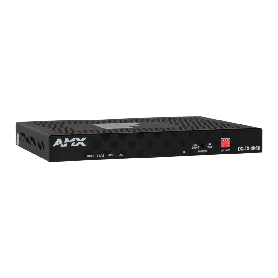
Transmission Distance Cable Type Range Supported Video 1080P@60Hz, 48bpp 1080P@60Hz,3D Cat 6 70m/230ft 4K@30Hz, 4:4:4, 32bpp Cat 6a/7 100m/330ft 4K@60Hz, 4:2:0, 32bpp 4K@60Hz, 4:4:4, 24bpp Hardware Description DX-TX-4K60 Transmitter Front View STATUS LED LINK LED USB MODE POWER LED HDCP LED DIP SWITCH ID Pushbutton POWER LED: On indicates when the Transmitter is powered on. -
Page 12: Dx-Rx-4K60 Receiver
AUDIO IN: Audio input, 3.5mm Mini-Stereo Jack. HDMI OUT: Connect to an HDMI display. Support digital video and embedded digital audio. ICS LAN 10/100: RJ45 port, TCP/IP Port. For ethernet 10/100 connectivity (receive commands or download upgrade file). IR RX: Connect to an IR receiver provided. - Page 13 HOST: USB Type-B connector. Connect to a USB host device. NOTE: When you want to connect USB devices to the Host PC of the receiver, ensure the USB Mode Switch on front panel is set to “USB HOST” position. USB: USB Type-A connector.
-
Page 14: Pinout Information
Pinout Information RS232 Connects to a RS232 device with the 3-pole, 3.5mm captive screw connectors. Wire as shown below: Twisted Pair cable The pinout in the following picture is for twisted pair cable that connects to the ICS LAN 10/100 connector (on modules only) or to the DXLink connector on all Transmitters and Receivers. -
Page 15: Rj-45 Leds
RJ-45 LEDs ICS LAN 10/100 Connector LEDs (DXLINK Modes only) The following information applies to the LEDs on the ICS LAN 10/100 connector on DXLink modules. Note that #1 Toggle must be set to ON or ICS LAN functionality will not be provided. Yellow LE D Green LED ICS LAN 10/100 Connector LEDs... -
Page 16: Quick Reference Tables For Modes
Quick Reference Tables for Modes The modes listed in the following three tables are those supported by DXLink Transmitters and Receivers. The Quick Reference Tables are intended to help users navigate the many modes available for system setup and use. For complete information on any of the modes listed, see the relevant sections or chapter referenced at the end of the Descriptions. - Page 17 Quick Reference Table - Modes for Handling Addressing/Networking Mode Description Ethernet Modes Speed/Duplex Mode: (continued) This mode configures the LAN driver to calculate its speed as either 10 or 100 and to communicate in either half- or full-duplex. Ethernet Mode discovery and configuration information is available through ...
- Page 18 Quick Reference Table - Modes for Handling Video Processing Mode Description Scaling Scaling Modes refer to how the system alters or maintains a source device’s resolution as it is passed along to the destination device. The Scaling Mode can be set through RX Web UI, with SEND_COMMANDs, or through DGX Configuration Software when scaling is being done via an Enova DXLink Output Board.
-
Page 19: Dip Switch Function
DIP Switch Function The DIP Switch is located on the front panel of DX-TX-4K60 and DX-RX-4K60, the functions is descripted as follows. #1 Toggle is used for enabling/disabling the physical ICS LAN 10/100 port. #2 Toggle is used for setting Modules to either automatically or manually determine the DXLink Mode. ... -
Page 20: Toggle Settings
type of DXLink equipment they are connected to and will automatically self-configure to be in one of two DXLink Modes based on the connection: Extender Mode – This mode is automatically selected when a TX and RX are connected directly to each other (a standalone pair). -
Page 21: Scenarios / Dip Switch Settings Table
Scenarios / DIP Switch Settings Table The table below contains the most common scenarios for setting up Transmitter and Receiver as a standalone pair or with other equipment. Find the scenario in the table that you want to use and then set the Dip switches accordingly. A detailed explanation of functions for each toggle is provided above and on the previous page. -
Page 22: Installation And Wiring
Installation and Wiring Installation Note: Before installation, please ensure the kit is disconnected from the power source. Steps to install the device in a suitable location: Attach the installation brackets to the enclosure using the screws provided in the package. The bracket is attached to the enclosure as shown. - Page 23 network and connect the PC to ICSLAN port on the other receiver or transmitter. RS232 Pass-Through: Connect an RS232 device to RS232 port of transmitter or receiver. Connect the transmitter and receiver to the DC 12V power adapters provided. Endpoint Mode (Standalone) A standalone DXLink TX/RX pair are connected directly to each other but, in addition, either the TX or RX is connected to a NetLinx Central Controller via a LAN or directly to the Controller.
- Page 24 Extender Mode (Standalone) Display Local Area Network (Public) HDMI IN HDMI LOOP OUT Transmitter Cat x Receive r HDMI OUT Display Endpoint Mode (Standalone) Display Local Area Network (Public) NetLinx Central Controller HDMI IN HDMI LOOP OUT Transmitter Cat x Receiver HDMI OUT Display...
-
Page 25: Netlinx Binding Of Dxlink Modules With An Enova Dgx Switcher
Endpoint Mode (Switcher) Cat x HDM I IN Cat x Transmitter Receive r HDM I OUT Display NetLinx Binding of DXLink Modules with an Enova DGX Switcher NOTE: If a DXLink module has been configured for auto-setup mode and then auto-setup mode has been disabled, the unit may take longer to appear in NetLinx Studio than expected (1-2 minutes). -
Page 26: Avoiding Network (Ethernet) Loops
Avoiding Network (Ethernet) Loops CAUTION: Be careful not to create a network (Ethernet) loop. Only one connection to a Public LAN is permitted within a switching system with DXLink support. Network loops must be avoided. Example In the example in following figures, a network loop was created when the Enova DGX switcher was connected to a Public LAN and one of its DXLink 4K Receivers was connected to the same LAN. -
Page 27: Configuring Usb For Use With A Dgx Or Dvx
INDICATOR LEDS Normal POWER UP INDICATES HDCP Indicator Yellow (On/Blinking) HDCP-protected content is being transmitted or not RX-Scaling Blue or Off Scaling on or off NetLinx Link/Act Green (ON/Blinking- #3 Toggle Off) Active LAN connection to an AMX Network or receiving Ethernet data packets Configuring USB for use with a DGX or DVX The USB Modes can be set by USB DIP Switch on the front panel of the transmitter/receiver. -
Page 28: Id Pushbutton Operation
ID Pushbutton Operation The ID Pushbutton is located on the right front of DXLink Modules The ID Pushbutton can be used to perform five types of initial configuration settings: Toggle between DHCP and static IP addressing (see below) Assign a device address Reset the unit to factory default settings, which affects the parameters but not the firmware version Restore the unit to its factory firmware image, which affects both the firmware version and the parameters Show IP Address (OSD) - Page 29 (4) In the ID Mode section, enter the Device and System numbers that you want assigned to the device in the appropriate text boxes. (5) Click Start Identify… to place the named system in ID Mode. The button changes to “Cancel Identify Mode” (click to cancel ID Mode). The text box below the button displays a “Waiting...Press Cancel to Quit”...
- Page 30 the faster blink rate. (2) At the point that the blink rate increases, release the ID Pushbutton to enter and start reset to factory default settings mode. (3) Reset factory default settings mode will start and the Link and Status LEDs will turn off. (4) Once the factory settings are reset, the Link and Status LEDs will return to normal operation.
-
Page 31: Id Pushbutton Boot States And Led Behavior
Access to Field Update Mode Use a USB drive to upgrade firmware (Including Kernel/APP of ARM, APP of STMCU, APP of EP, APP of 6488, APP of DSC module) through the USB (Type-A) port. For details, see “Upgrade the firmware through USB Port” in the FIRMWARE UPGRADE section of this document. -
Page 32: Rs232 And Ir Operations
RS232 and IR Operations The RS232 and IR ports have multiple modes according to the three DXLink connection modes. RS232 Operations The RS232 (serial) ports are the 3-position screw terminal blocks (see “Pin Information” Section) on the rear of the modules. -
Page 33: Ir Operations
Flow Control”): (1) Wire the RS232 connectors on Modules according to the pinout directly (see “Pin Information” Section) above the connector. (2) Use the command to enable this port on Transmitter and Receiver Modules (complete Serial SEND_COMMAND programming information is available on “APPENDIX C: ICSP Commands” section). IR Operations The IR ports are the 3.5mm port on the rear panel of the modules. - Page 34 independently from the routing of the video signals). For additional information on Endpoint Mode, see “Installation and Wiring” section. For IR SEND_COMMANDs, see “APPENDIX C: ICSP Commands” section. See the diagram “Serial Data Transfer and IR Flow Control”. IMPORTANT: When a Transmitter and Receiver are used as a standalone pair, IR control is passed through directly in Extender Mode, when #2 Toggle is set to OFF (default).
-
Page 35: Network Configuration
Network Configuration IMPORTANT: If DXLink Modules are connected to an Enova DGX 100 Series Switcher using auto-setup, see the “Hardware Reference Manual – Enova DGX 100 Series Digital Medial Switchers” for network configuration information. NOTE: If a DXLink Module has been configured for auto-setup mode and then auto-setup mode has been disabled in the switcher, the unit may take longer to appear in NetLinx Studio than expected (1-2 minutes). -
Page 36: Tcp/Ip Address Configuration
and other network parameters). Should the attempt fail, the Module will then configure itself for a link-local address. DXLink Modules utilize a modified link-local addressing procedure. The first address to be tried is a known address in the link-local space: 169.254.2.2. That address will be probed, and if unclaimed will be used by the DXLink Module. -
Page 37: Netlinx Programing
NetLinx Programing Advanced users may also choose to control the DX-TX/RX-4K60 through NetLinx Studio via the ICS LAN 10/100 port on endpoint mode (standalone mode). Or connect the devices to DGX or DVX switcher in endpoint mode (switcher). NOTE: For additional information on using NetLinx Studio, refer to the WebConsole & Programming Guide – NX-Series Controllers (available at www.amx.com). -
Page 38: Send Commands To Control A Device
Send Commands to control a device Click "Diagnostics" on the menu bar, choose "Control a Device". A window will display as follows, enter the device number, Port number, and System number in Device, Port, System boxes according to the previous section, and enter a command in the textbox, and click "Send To Device". -
Page 39: Telnet Control
Telnet Control Choose the device you want to control, right click, then choose “TELNET Window”->“Launch TELNET window via NetLinx Studio”, enter the telnet window, input telnet commands in this window to control the device. NOTE: More Commands, please refer to “APPENDIX B: Telnet Commands” section. At the prompt (>), type the Telnet command and press Enter. -
Page 40: Send Commands To Control A Device
Device number DXLink Transmitter Ports 1-14 on DX-TX-4K60 Get detail information about installation, see “Wiring” part of “Installation and Wiring” Section. Launch NetLinx Studio and open the Online Tree. Bind the target device to the integrated Central Controller: select and right-click the DX-TX-4K60/DX-RX-4K60: from the context sensitive menu, select “Network Bind/Unbind Device”... -
Page 41: Telnet Control
Telnet Control Choose the device you want to control, right click, then choose “TELNET Window”->“Launch TELNET window via NetLinx Studio”, enter the telnet window, input telnet command in this window to control the device. NOTE: More Commands, please refer to “APPENDIX B: Telnet Commands” section. At the prompt (>), type the Telnet command and press Enter. - Page 42 Hardware Reference Manual...
-
Page 43: Web Ui Control
Web UI Control The Web UIs designed for the DX-TX-4K60 and DX-RX-4K60 allow basic controls and advanced settings of the device. The Web UI page can be accessed through NetLinx Studio or through a browser with latest version, e.g. Chrome, Firefox, Safari, Opera, Edge, etc. -
Page 44: Web Ui Of Dx-Tx-4K60
Web UI of DX-TX-4K60 Input the password then Login to enter the following page. The default password is “admin”. The main page includes five submenus: Video, Audio, Control, Network, and System. Web Introduction Logout Click the icon to return to the login page. Video (1) HDCP Settings Set HDCP Compliance enable or disable. - Page 45 Click to set HDMI Loop Out video mute/unmute. The default setting is Unmute. (3) General This section shows the current EDID, and allows you select EDID Mode, Preferred EDID, Save EDID and Load EDID. Resolution: Shows the resolution of current input signal. ...
- Page 46 (4) HDR Mode This section allows you to select HDR mode to HDR 10 or None. The default setting is None. Audio This Section allows you to set Audio Priority auto or manual, Audio Source selection, and set Audio format. Audio Priority: Set Audio Priority to Auto/Manual.
- Page 47 Control This section includes DXLINK Modes, CEC Setting, RS232 Setting, IR Settings parts. Hardware Reference Manual...
- Page 48 (1) DXLINK Mode Endpoint: Click to set the device to Endpoint mode. Extender: Click to set the device to Extender Mode. NOTE: When the device is in Endpoint Mode, the CEC, RS232 and IR Settings are in NetLinx mode and can’t be set ...
- Page 49 (3) RS232 Setting Mode: Select RS232 control mode. When the endpoint is set to Extender mode, the default setting is Passthrough. In passthrough mode, all RS232 signals pass through between the RS232 transmitter and receiver. When set to Local mode the following items can be configured: Manual Power On/Off: After set the commands of Power On/Off, click ON/OFF to send the commands to the ...
- Page 50 (4) IR Setting When the DXLINK Mode is set to Extender Mode: Mode: Select IR control mode. The default setting is Passthrough. In Passthrough mode IR signals are passed through from IR transmitter to IR receiver. When the mode is set to Local, the following items can be configured: Manual Power On/Off: After setting Power On/Off commands and finish IR learning, click to turn on/off the ...
- Page 51 Network This Section allows you to set Network. IP Mode: DHCP: When enabled, the IP address will be assigned automatically by the DHCP server connected. Static: When enabled, set up the IP address manually. Mac Address: Show mac address of the device. ...
- Page 52 System This section includes ten submenus to get system status and configure system items. (1) Firmware Version This section shows the firmware version of the device. Hardware Reference Manual...
- Page 53 (2) ICSP Parameter Controller URL In this column, users can set ICSP parameters. Connection Mode: Includes four options of NDP, Auto IP, URL/TCP, URL/UDP. The default setting is NDP. Controller URL: Input the connected Central Controller’s URL. System Number: Use the Online Tree to determine it. By default, it is disabled to configure. ...
- Page 54 SSH Account is used to configure the SSH connection on/off, username and password of the account. For SSH Account, the default username is admin, the default password is password. Apply: Click to perform the settings. It will perform reboot the device to take effect. ...
-
Page 55: Web Ui Of Dx-Rx-4K60
Apply: Click “Apply”, it will perform to reboot the device to take effect. (9) Device Configuration Save Config: Click to save the current configuration as a bin file to local PC. Load Config: Click to load the saved configuration bin file. ... -
Page 56: Web Ui Introduction
Web UI Introduction Video (1) General Scaling Mode: Select Scaling mode. The default setting is Auto. Auto: Auto Mode will configure the scaler settings based on EDID information received from the connected display. Manual: Manual Mode allows the user to configure the output resolution of the video that will be transmitted ... - Page 57 to the destination device. Bypass Mode: Bypass Mode enables the receiver to pass video without alteration by the internal scaler. Resolution: When setting scaling mode to Manual, select the resolution from the drop-down menu. Show only EDID Display Supported (DS): Click to select the item to change the resolution menu according the ...
- Page 58 Video Mute: Click to mute/unmute the video. The default setting is Unmute. Video Freeze: Click to freeze/unfreeze the video. The default setting is Unfreeze. Test Patten: Click to select test Patten from the drop-down menu. The default setting is NONE. ...
- Page 59 OSD Color: Set OSD display color from the drop-down menu. The default setting is white characters on black background. OSD Position: Set OSD display position on the display. The default setting is Top Left. (6) Image Adjustments This section allows you to adjust the brightness and contrast of the image. Brightness: Slide the button to adjust the brightness of the image.
- Page 60 Control (1) DXLINK Mode Endpoint: Click to set the device to Endpoint mode. Extender: Click to set the device to Extender Mode. NOTE: When the device is in Endpoint Mode, the CEC, RS232, and IR Settings are configured through NetLinx and can’t ...
- Page 61 (2) CEC Settings This section is used to set CEC settings parameters. Mode: Select CEC mode. When the endpoint is set to Extender mode, the default CEC Mode is Passthrough. In passthrough mode, all CEC commands are passed through between source and sink. When the mode is set to passthrough, the CEC function is Passthrough.
- Page 62 third-party device. Auto Power On/Off: Set Auto Power On/Off. The default setting is ON. Delay Time: When Auto Power On/Off is set to ON, Choose Auto Control time to send power off command time. For example, if the time is set to 2 minutes, when the output has no signal for more than 2 minutes, the device will power off automatically.
- Page 63 2min. Power On: Enter the IR command to turn on the third-party device. Power Off: Enter the IR command to turn off the third-party device. Note: IR Learning Steps under Local Mode: Connect IR Receiver cable to IR RX port. Press Power On/Off button on remote controller.
- Page 64 System (1) Firmware Version This section shows the current firmware version. Hardware Reference Manual...
- Page 65 (2) ICSP Parameter Controller URL In this column, users can set ICSP parameter. Connection Mode: Includes four options of NDP, Auto IP, URL/TCP, URL/UDP. The default setting is NDP. Controller URL: Input the connected Central Controller’s URL. System Number: Use the Online Tree to determine it. By default, it is disabled to configure. ...
- Page 66 (5) SSH Account SSH Account is used to configure the SSH connection on/off, username and password of the account. For SSH Account, the default username is admin, the default password is password. Apply: Click to perform the settings. It needs to reboot the device to take effect. ...
- Page 67 (8) Login Password This section allows you to change login password. Apply: Click to save the settings. The default password is “admin”. (9) Device Configuration Save Config: Click to save the current configuration as a bin file to local PC. ...
-
Page 68: Firmware Upgrade
Firmware Upgrade DX-TX-4K60 and DX-RX-4K60 can use ‘KIT’ files or ‘.swu’ files for firmware upgrade. Upgrade Firmware through NetLinx Before You Start Verify that you have the latest version of NetLinx Studio on your PC. If the version is not the latest – Use the Web Update option in NetLinx Studio’s Help menu to obtain the latest version. -
Page 69: Upgrade The Firmware Through Usb Port
NOTE: Use the Online Device Tree to determine the device’s assigned IDs, if it has been changed. Click Send to upgrade the firmware on the DXLink-TX-4K60/DX-RX-4K60. The Power LED blinks during the process for upgrading the firmware (this is normal). ... -
Page 70: Appendix A: Factory Default Configuration
APPENDIX A: Factory Default Configuration Factory Default Configuration Hardware Default Setting Switcher Setting TX - USB Host, USB Mode Switcher RX - USB Device 4-Pin DIP Switcher 0000 (O-OFF,1-ON) Software Default Parameters Parameter Value MAC Address As set in factory Serial Number As set in factory Ethernet Mode... - Page 71 Factory Default Configuration SSH Username " " (blank, no username) SSH Password " " (blank, no password) Telnet Username " " (blank, no username) Telnet Password " " (blank, no password) Standalone Webserver Password admin Transmitter Only VIDIN_RES_AUTO ENABLE VIDIN_EDID ALL RESOLUTIONS VIDIN_PREF_EDID 4096X2160,30...
-
Page 72: Appendix B: Telnet Commands
… … > >device status 32002:1:0 Displays device status of a specified device, port, system (<D:P:S>). Device Status ------------- Device 32002 Harman International, DX-TX-4K60, V1.2.11 contains 14 Ports Channels:255 Levels:8 MaxStringLen=2048 Types=8 bit MaxCommandLen=1024 Types=8 bit The following input channels are... - Page 73 Command Description Example >get config Displays the current connection settings. Device number: 7010 Connection Settings -------------------------------- Mode: NDP System Number: 2155 Central Controller IP/URL: 192.168.43.83 Central Controller Port: 1319 Username: The username of telnet Password: The password is not displayed IP Settings -------------------------------- HostName: DXL-RX-36d0110...
- Page 74 Command Description Example >get ethernet mode Displays the current LAN configuration. GET ETHERNET MODE Ethernet mode is auto. Displays the device’s friendly name (for NDP). GET FRIENDLY >get ip Show the IP configuration of this device. The device displays its D:P:S, Host Name, Type HostName DXL-RX-36d0110 (DHCP or Static), IP Address, Subnet Mask, Type DHCP...
- Page 75 Command Description Example >ping 192.168.29.209 Pings an address (IP or URL), to test network connectivity to and confirms the presence of 192.168.29.209 is alive. PING [ADDRESS] another networked device. > The syntax matches to the PING application in Windows or Linux. >REBOOT Reboots the device.
- Page 76 Command Description Example new settings. NOTE: These changes do not require a reboot to take effect. >set dns Sets the DNS configuration of the DXLink Transmitter or Receiver, only as applied to Static -- Enter New Values or just hit Enter IP Mode (DNS settings in DHCP Mode are to keep current settings -- received from the DHCP server).
- Page 77 Command Description Example >set ip Sets the IP configuration of a specified device. Enter a Host Name, Type (DHCP or Fixed), IP Address, Subnet Mask, and Gateway IP Address. --- Enter New Values or just hit Enter IMPORTANT: Host Names may only contain to keep current settings --- ASCII letters “a”...
- Page 78 Command Description Example the change to take effect. NOTE: This command requires a reboot to enable new settings. IMPORTANT: If you set the Telnet port to “0” to disable it, you will need to reset it with a SEND_COMMAND in NetLinx Studio Shows the Central Controller connection log for SHOW CONNECTION LOG the device.
-
Page 79: Appendix C: Icsp Commands
APPENDIX C: ICSP Commands DX-TX-4K60 Description Command Example Video SEND_COMMANDs are sent to Port 7 Command: Command: SEND_COMMAND <DEV>, SEND_COMMAND "'?VIDIN_STATUS'" VIDEO_INPUT_1,"'?VIDIN_STATUS'" Return: Return: VIDIN_STATUS-<status> VIDIN_STATUS-VALID SIGNAL Description: Description: Request the status of the video input on There is a Valid signal on input HDMI port. ?VIDIN_STATUS the Transmitter. - Page 80 Description Command Example Variables: ENABLE - Default, the preferred resolution for video input port is generated by comparing HDMI loop port EDID and DXLink port EDID (Smart EDID) DISABLE - the preferred resolution is manually defined by VIDIN_EDID Command: Command: SEND_COMMAND...
- Page 81 Description Command Example Command: Command: SEND_COMMAND <DEV>,"'?VIDIN_EDID'" SEND_COMMAND VIDEO_INPUT_1,"'?VIDIN_EDID'" Return: Return: VIDIN_EDID-<source> VIDIN_EDID-MIRROR OUT 1 Description: Description: Request the EDID source is in active status on video input port. Current active EDID is Copy from sink display on DXLink port for video input port. Variables: ?VIDIN_EDID source =...
- Page 82 Description Command Example Command: Command: SEND_COMMAND <DEV>,"'VIDIN_HDR- SEND_COMMAND dvTX,"'VIDIN_HDR- <HDR10|NONE>'" HDR10'"" Return: Return: VIDIN_HDR-<HDR10 | NONE> VIDIN_HDR-HDR10 VIDIN_HDR Description: Description: Set Input EDID to support HDR10 or Set input EDID with HDR10 video support to NONE. be enabled. Variables: NONE (Default): no HDR is supported ...
- Page 83 Description Command Example 2C 2D 2F 30 31 01 23 09 07 07 1A 36 80 A0 70 38 1F 40 30 20 35 00 40 84 63 00 00 1A 46 37 80 70 72 38 22 40 70 C8 35 00 40 84 63 00 00 1C D1 3D 80 80 72 B0 26 40 78 C8 36 00 40 E8 63 00 00 1C 28 3C 80 A0 70 B0 23 40 30 20 36 00 40 E8...
- Page 84 Description Command Example Command: Command: SEND_COMMAND SEND_COMMAND <DEV>,"'VIDIN_FORMAT-< HDMI | VIDEO_INPUT_1,"'VIDIN_FORMAT-DVI'" DVI >'" Return: VIDIN_FORMAT Return: VIDIN_FORMAT-DVI VIDIN_FORMAT-< HDMI | DVI > Description: Description: Set DVI format to HDMI Input port. Set the video format on the Transmitter Command: Command: SEND_COMMAND SEND_COMMAND <DEV>,"'?VIDIN_FORMAT'"...
- Page 85 Description Command Example Command: Command: SEND_COMMAND <DEV>, SEND_COMMAND "'?VIDOUT_SCALE'" VIDEO_OUTPUT_1,"'?VIDOUT_SCALE'" Return: Return: VIDOUT_SCALE-<mode> VIDOUT_SCALE-BYPASS ?VIDOUT_SCALE Description: Description: Requests the current Scaling Mode that Scaler mode is set to Bypass. the Transmitter is set to. Variables: mode = BYPASS, DOWNSTREAM CEC SEND_COMMANDs are sent to Port 6 and Port 9 Command: Command: SEND_COMMAND...
- Page 86 Description Command Example Command: Command: SEND_COMMAND SEND_COMMAND <DEV>,"VIDOUT_CEC_MAKEACTIVE'" dxTX,"'VIDOUT_CEC_MAKEACTIVE'" VIDOUT_CEC_MAKE Return: Return: ACTIVE VIDOUT_CEC_MAKEACTIVE VIDOUT_CEC_MAKEACTIVE Description: Description: Set sink TV to turn on and make this Set sink TV to turn on and make this HDMI to HDMI to be connected the active source. be connected to the active source.
- Page 87 Description Command Example Audio SEND_COMMANDs are sent to Port 7 Command: Command: SEND_COMMAND SEND_COMMAND dvTX,"'AUDIN_DIGITAL- <DEV>,"'AUDIN_DIGITAL-<format>'" AC3'" Return: Return: AUDIN_DIGITAL-<format> AUDIN_DIGITAL- AAC Description: Description: Set the audio format of EDID for the Set audio format of input EDID to AAC Audio specified Audio input port.
- Page 88 Description Command Example Command: Command: SEND_COMMAND <DEV>, SEND_COMMAND VIDEO_IN_1, "'AUDIN_FORMAT_AUTO-<ENABLE | "'AUDIN_FORMAT_AUTO-ENABLE'" DISABLE>'" Return: Return: AUDIN_FORMAT_AUTO-ENABLE AUDIN_FORMAT_AUTO-<ENABLE | Description: DISABLE> Auto detecting and selecting the audio AUDIN_FORMAT_A Description: source between HDMI Embedded Audio or Set audio source format to automatically External Analog audio is set to enable.
- Page 89 Description Command Example Variables: format = HDMI (Default) ANALOG, IR SEND_COMMANDs are sent to Port 3 (IR TX port) Function channel Generate the IR or serial command assigned to that channel 1-255 Command: Command: SEND_COMMAND <DEV>,"'CAROFF'" SEND_COMMAND IR_1,"'CAROFF'" Return: Return: CAROFF CAROFF CAROFF...
- Page 90 Description Command Example programmed, the module performs the following steps: Transmits IR signals for Enter (IR code 21). Waits for the time set with the CTOF command to elapse. Command: Command: SEND_COMMAND <DEV>,"'CP',<code>" SEND_COMMAND IR_1,"'CP',2" Description: Halt and clear all active or buffered IR commands, and then send a single IR pulse.
- Page 91 Description Command Example Command: Command: SEND_COMMAND <DEV>,"'GET BAUD'" SEND_COMMAND dvRXRS232,"'GET BAUD'" GET BAUD Description: Description: Get the IR port’s current The port responds with: communication parameters. Port <port #>, <baud>, <parity>, <data>, <stop> Command: Command: SEND_COMMAND <DEV>,"'GET MODE'" SEND_COMMAND IR_1,"'GET MODE'" Description Description: The port responds with:...
- Page 92 Description Command Example Set the IR/Serial ports for IR or Serial- controlled devices to either IR, Serial, or Data mode. Variables: Valid response: mode = IR (standard IR output with carrier) SERIAL (IR without carrier and waveform inverted) DATA (1-way serial/TTL) Command: Command: SEND_COMMAND <DEV>,"'SP',<code>"...
- Page 93 Description Command Example the 'B9MON' command. Disables 9-bit in 232 mode. By default, this returns the Communication settings on the serial port to the last programmed parameters. Command: Command: B9MON SEND_COMMAND SOMEDEVICE_1,"'B9MON'" Description Description: Override and set the current Reset the SOMEDEVICE port’s communication settings and communication parameters to nine data bits B9MON...
- Page 94 Description Command Example Command: Command: SEND_COMMAND <DEV>,"'ESCSEQON'" SEND_COMMAND dvRX,"'ESCSEQON'" Description: Description: ESCSEQON Enables SEND_STRING escape sequences. Enable SEND_STRING escape sequences (see the "SEND_STRING Escape Sequences" section. Command: Command: SEND_COMMAND <DEV>,"'GET BAUD'" SEND_COMMAND dvRXRS232,"'GET BAUD'" Description: Description: GET BAUD Get the RS-232 (serial) port’s current The port responds with: communication parameters.
- Page 95 Description Command Example Command: Command: SEND_COMMAND <DEV>,"'SET BAUD SEND_COMMAND DEVICE_1,"'SET BAUD <baud>,<parity>,<data>, <stop>'" 115200,N,8,1'" Description: Description: Use either of these commands to set the Set the DEVICE_1 port’s communication serial communication parameters. parameters to 115,200 baud, no parity, 8 data bits, and 1 stop bit. SET BAUD NOTE: DXLink Receivers only support RS- (shown in s)
-
Page 96: Dx-Rx-4K60
Description Command Example Command: Command: SEND_COMMAND SEND_COMMAND RS232_1,"'27,19,10'" <DEV>,"'27,19,<time>'" Description: Description: Insert a 10-millisecond delay before 27, 19 Insert a time delay before transmitting characters to the RS232_1 transmitting the next character device. Variables: time = 1 to 255, (measured in 1 millisecond increments) DX-RX-4K60 Description... - Page 97 Description Command Example Variables: Valid responses: pattern = OFF, RED, GREEN, BLUE Command: Command: SEND_COMMAND SEND_COMMAND <DEV>,"'?VIDOUT_TESTPAT'" dvRX,"'?VIDOUT_TESTPAT'" Return: Return: VIDOUT_TESTPAT-<pattern> VIDOUT_TESTPAT-RED ?VIDOUT_TESTPAT Description: Description: Request the test pattern setting on the The test pattern setting on the video output Receiver.
- Page 98 Description Command Example Command: Command: SEND_COMMAND SEND_COMMAND dvRX,"'VIDOUT_LOGO- <DEV>,"'VIDOUT_LOGO-<mode>'" DRAG BOTTOM LEFT'" Return: Return: VIDOUT_LOGO-<mode> VIDOUT_LOGO-DRAG BOTTOM LEFT Description: Description: VIDOUT_LOGO Set the LOGO move mode of the video Set the LOGO move mode from Center to blanking for the specified video port bottom left.
- Page 99 Description Command Example Command: Command: SEND_COMMAND SEND_COMMAND <DEV>,"'VIDOUT_RES_REF- VIDEO_OUTPUT_1,"'VIDOUT_RES_REF- <horizontal>x<vertical>,<refresh- 3840x2160,60'" rate>'" Return: Return: VIDOUT_RES_REF-3840x2160,60 VIDOUT_RES_REF- Description: <horizontal>x<vertical>,<refresh-rate> HDMI out resolution is 3840x2160@60. Description: Set the resolution and refresh rate of the video through the Receiver, and set Scalar mode to be MANUAL mode Variables: Variables: horizontal = An integer value...
- Page 100 Description Command Example Command: Command: SEND_COMMAND <DEV>, SEND_COMMAND "'?VIDOUT_RES_REF'" VIDEO_OUTPUT_1,"'?VIDOUT_RES_REF'" Return: Return: VIDOUT_RES_REF- VIDOUT_RES_REF-3840x2160,60 <horizontal>x<vertical>,<refresh-rate> Description: Description: HDMI out resolution is 3840x2160@60. Request the resolution and refresh rate of the video through the Receiver. ?VIDOUT_RES_REF Variables: <horizontal>x<vertical>,<refresh- rate> 4096x2160,60 4096x2160,30 …...
- Page 101 Description Command Example YUV444 Command: Command: SEND_COMMAND <DEV>, SEND_COMMAND "'?VIDOUT_COLOR_SPACE'" dvRX,"'?VIDOUT_COLOR_SAPCE'" Return: Return: VIDOUT_COLOR_SPACE-<format> VIDOUT_COLOR_SPACE-RGB Description: Description: ?VIDOUT_COLOR_SPAC Request the scaler output color space The scaler output color space is RGB. for receiver. Variables: format = RGB (Default) YUV444 Command: Command: SEND_COMMAND SEND_COMMAND...
- Page 102 Description Command Example Command: Command: SEND_COMMAND <DEV>, SEND_COMMAND "'?VIDOUT_MUTE'" SWITCHER,"'?VIDOUT_MUTE'" Return: Return: ?VIDOUT_MUTE VIDOUT_MUTE<ENABLE|DISABLE> VIDOUT_MUTE-DISABLE Description: Description: Request the setting for the Mute Video mute mode is disable preference applied to the image from the Receiver. Command: Command: SEND_COMMAND SEND_COMMAND <DEV>,"'VIDOUT_MUTE-<ON|OFF>'"...
- Page 103 Description Command Example Command: Command: SEND_COMMAND SEND_COMMAND <DEV>,"'VIDOUT_SLEEP_DELAY- SWITCHER,"'VIDOUT_SLEEP_DELAY-60'" <timer>'" Return: Return: VIDOUT_SLEEP_DELAY-60 VIDOUT_SLEEP_DELAY-<timer> VIDOUT_SLEEP_DELAY Description: Description: Set HDMI TMDS sleep delay to be 60 when Set the TMDS clock behavior when no no output signal. output signal on HDMI out. Variables: timer = [0…32737] (Default =30) Command:...
- Page 104 Description Command Example Command: Command: SEND_COMMAND SEND_COMMAND <DEV>,"'VIDOUT_CONTRAST-<value>'" dvRX,"'VIDOUT_CONCTRST-75'" Return: Return: VIDOUT_CONTRAST-<value> VIDOUT_CONTRAST-75 VIDOUT_CONTRAST Description: Description: Set the contrast setting on the specified Set Video Contrast to 75. video output port. Variables: value = [0…100], default = 50 and 50 is bypass for video input contrast Command: Command:...
- Page 105 Description Command Example Command: Command: SEND_COMMAND <DEV>, SEND_COMMAND "'?VIDOUT_OSD_COLOR-<color>'" dvRX ,"'?VIDOUT_OSD_COLOR-BLACK'" Return: Return: VIDOUT_OSD_COLOR-<color> VIDOUT_OSD_COLOR-BLACK Description: Description: Set the On-Screen Display (OSD) color Set OSD Color on video output port to scheme on the display connected to the BLACK VIDOUT_OSD_COLOR specified video port.
- Page 106 Description Command Example BTM LEFT Command: Command: SEND_COMMAND <DEV>, SEND_COMMAND "'?VIDOUT_OSD_POS'" dvRX ,"'?VIDOUT_OSD_POS'" Return: Return: VIDOUT_OSD_POS-<position> VIDOUT_OSD_POS-TOP RIGHT Description: Description: Request the On-Screen Display (OSD) OSD position on video output port is TOP position on the display connected to the RIGHT ?VIDOUT_OSD_POS specified video port.
- Page 107 Description Command Example Command: Command: SEND_COMMAND SEND_COMMAND <DEV>,"'?VIDOUT_HDCP'" VIDEO_INPUT_1,"'?VIDOUT_HDCP'" Return: Return: VIDOUT_HDCP-<mode> VIDOUT_HDCP-FOLLOW Description: Description: Get HDCP compliance setting of the Video output with HDCP encryption following ?VIDOUT_HDCP specified video output port. sink display. (NOTE: There is one exception, if sink display is Non-HDCP compliance, Variables: works as HDCP repeater, as it is illegal to mode =...
- Page 108 Description Command Example CEC SEND_COMMANDs are sent to Port 6 Command: Command: SEND_COMMAND SEND_COMMAND <DEV>,"VIDOUT_CEC_POWER- <DEV>,"'VIDOUT_CEC_POWER-OFF'" <ON|OFF>'" Return: VIDOUT_CEC_POWER Return: VIDOUT_CEC_POWER-OFF VIDOUT_CEC_POWER-<ON|OFF> Description: Description: Set power status to OFF on sink display. Set power status to on/off on the sink display.
- Page 109 Description Command Example Command: Command: SEND_COMMAND SEND_COMMAND <DEV>,"'CEC_DISP_AUTO- <DEV>,"'CEC_DISP_AUTO-<ON|OFF>'" OFF'" Return: Return: 'CEC_DISP_AUTO-<ON|OFF> CEC_DISP_AUTO-OFF CEC_DISP_AUTO Description: Description: Set power control of sink display Set the function to OFF for power control of automatically according to detect active sink display automatically. input signal and its own power boot-up state.
- Page 110 Description Command Example Command: Command: SEND_COMMAND <DEV>, SEND_COMMAND dxDev, "'?AUDOUT_MUTE'" "'?AUDOUT_MUTE'" Return: Return: AUDOUT_MUTE-DISABLE ?AUDOUT_MUTE AUDOUT_MUTE-<ENABLE|DISABLE> Description: Description: Audio mute mode is disable. Request the setting for the Mute preference of the audio from the Receiver. Command: Command: SEND_COMMAND SEND_COMMAND dvRX,"'AUDOUT_FORMAT- <DEV>,"'AUDOUT_FORMAT-<format>'"...
- Page 111 Description Command Example IR SEND_COMMANDs are sent to Port 3 (IR TX port) Function Channel Generate the IR or serial command assigned to that channel 1-255 Command: Command: SEND_COMMAND <DEV>,"'CAROFF'" SEND_COMMAND IR_1,"'CAROFF'" Return: Return: CAROFF CAROFF CAROFF Description: Disable the IR carrier signal until a 'CARON' Send Command is received.
- Page 112 Description Command Example Command: Command: SEND_COMMAND <DEV>,"'CTOF',<time>" SEND_COMMAND IR_1,"'CTOF',10" Description: Set the duration of the Off time (no signal) between IR pulses for channel and IR function transmissions. Off time settings are stored in non-volatile memory. CTOF This command sets the delay time between pulses generated by the 'CH' or 'XCH' send commands in tenths of seconds.
- Page 113 Description Command Example Command: Command: SEND_COMMAND <DEV>,"'IROFF'" SEND_COMMAND IR_1,"'IROFF'" IROFF Description: Description: Halt and clear all active or buffered IR Immediately halt and clear all IR output commands being output on the designated signals on the IR_1 port. port. Command: Command: SEND_COMMAND <DEV>,"'SET BAUD SEND_COMMAND DEVICE_1,"'SET BAUD...
- Page 114 Description Command Example code = IR code value 1 to 252 (253 to 255 reserved). Command: Command: SEND_COMMAND <DEV>,"'XCH SEND_COMMAND IR_1,"'XCH,30'" <channel>'" Return: Description: XCH 30 Transmit the selected channel IR codes in the format/pattern set by the XCHM command. Variables: Valid response: channel = 0 to 999.
- Page 115 Description Command Example This command works in conjunction with the 'B9MOFF' command. Enables 9-bit in 232 mode. Command: Command: SEND_COMMAND <DEV>,"'CHARD- SEND_COMMAND dvRXRS232,"'CHARD- <time>'" 10'" Description: Description: Set the delay time among all transmitted Set the delay time to 1-millisecond among CHARD characters to the value specified (in 100 all transmitted characters.
- Page 116 Description Command Example Command: Command: SEND_COMMAND <DEV>,"'RXCLR'" SEND_COMMAND dvRXRS232,"'RXCLR'" RXCLR Description: Description: Clear all characters in the receive buffer Clear all characters in the receive buffer waiting to be sent to the Central waiting to be sent to the Central Controller.
-
Page 117: Dx-Tx-4K60&Dx-Rx-4K60 Commands
SEND_STRING Escape Sequences are sent to Port 1 The DXLink Modules support several special SEND_STRING escape sequences. If any of the character combinations listed below are found anywhere within a SEND_STRING program instruction, they will be treated as a command and not the literal characters. Use the ESCSEQON and ESCSEQOFF NetLinx SEND_COMMANDS to control whether these are active or not. - Page 118 Description Command Example Command: Command: SEND_COMMAND <DEV>, "'REBOOT'" SEND_COMMAND 5002:1:0, "'REBOOT'" Return: Return: REBOOT REBOOT SEND_COMMAND 5002:1:0, Description: "'REBOOT'" Cause a warm reboot. Description: Cause a warm reboot. Command: Command: LED-DIS SEND_COMMAND DEVICE_1,"'LED- DIS'" Description: LED-DIS Description: Disable all LEDs to the right of the Program port.
- Page 119 Description Command Example Command: Command: SEND_COMMAND <DEV>,"'?DXLINK'" SEND_COMMAND dvRX,"'?DXLINK'" Return: Return: ?DXLINK DXLINK-<EXTENDER/ENDPOINT> DXLINK-EXTENDER Description: Description: Request the current mode for the TX or RX. Current DXLINK MODE is extender. Command: Command: SEND_COMMAND <DEV>,"'ICSLAN- SEND_COMMAND dvRX,"'ICSLAN- <ENABLE|DISABLE>'" ENABLE'" Return: Return: ICSLAN ICSLAN-<ENABLE|DISABLE>...
- Page 120 Description Command Example Command: Command: SEND_COMMAND <DEV>,"'PERSISTAV'" SEND_COMMAND dvRX,"'PERSISTAV'" Return: Return: PERSISTAV PERSISTAV Description: PERSISTAV Used to save the Receiver’s Power On Scaler settings/mode to the DGX DXLink Output Boards for DGX Configuration Software. Not required to save A/V settings to the receiver.
-
Page 121: Warranty Terms And Conditions
Warranty Terms and Conditions For the following cases AMX shall charge for the service(s) claimed for the products if the product is still remediable and the warranty card becomes unenforceable or inapplicable. The original serial number (specified by AMX) labeled on the product has been removed, erased, replaced, defaced or is illegible. - Page 122 © 2021 Harman. All rights reserved. SmartScale, NetLinx, Enova, AMX, AV FOR AN IT WORLD, and HARMAN, and Last Revised: their respective logos are registered trademarks of HARMAN. Any other company or brand name referenced may be trademarks/registered trademarks of their respective companies.
Need help?
Do you have a question about the AMX DXLINK DX-TX-4K60 and is the answer not in the manual?
Questions and answers