Table of Contents
Advertisement
Quick Links
Advertisement
Table of Contents

Related Manuals for Harman AMX IRIS


Summary of Contents for Harman AMX IRIS
- Page 1 IN STR U CT IO N MAN U AL I R I S IR/SERIAL DATA CAPTURE DEVICE...
- Page 2 IMPORTANT SAFETY INSTRUCTIONS READ these instructions. KEEP these instructions. HEED all warnings. FOLLOW all instructions. DO NOT use this apparatus near water. CLEAN ONLY with dry cloth. DO NOT block any ventilation openings. Install in accordance with the manufacturer's instructions. DO NOT install near any heat sources such as radiators, heat registers, stoves, or other apparatus (including amplifiers) that produce heat.
-
Page 3: Table Of Contents
Table of Contents Table of Contents IRIS Infrared/Serial Data Capture Unit ............4 Overview ........................... 4 Specifications ........................4 Front and Rear Panel Components ................... 5 Using the IRIS ....................6 Capturing HC Functions ....................6 Capturing HC functions in default mode ....................6 Capturing HC functions in SP mode ....................... -
Page 4: Iris Infrared/Serial Data Capture Unit
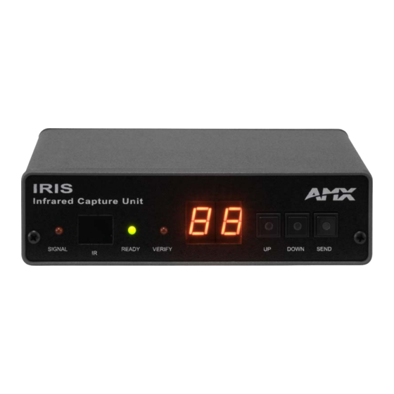
IRIS Infrared/Serial Data Capture Unit IRIS Infrared/Serial Data Capture Unit Overview The IRIS Infrared Capture Unit (FG5448) is a stand-alone, self contained unit used to capture infrared (IR) or wired-IR function signals from a hand-held remote controller. Hand controllers (HCs) are used to control a wide variety of audiovisual equipment that includes monitors, VCRs, TVs, and CD players. -
Page 5: Front And Rear Panel Components
IRIS Infrared/Serial Data Capture Unit Front and Rear Panel Components IR window Alphanumeric display SIGNAL LED SIGNAL READY VERIFY DOWN SEND SEND button READY LED DOWN button VERIFY LED UP button 8-pin data connector RS-232 12 V connector DB-9 connector RS-232 6-pin RJ-11 connector WIRED RS-232... -
Page 6: Using The Iris
Using the IRIS Using the IRIS Capturing HC Functions The two modes you can use to capture HC functions are default and special function. You use default mode, which is automatically set when you connect power to the IRIS unit, to capture the majority of HC functions. The table below shows the IRIS unit settings for default mode. -
Page 7: Display Characters And P Mode Settings
Using the IRIS Simultaneously press and release the , and pushbuttons to toggle the P mode setting On and Off. The display DOWN SEND then shows an On or Off message indicating the new P mode setting and then immediately exits the P mode. You can activate multiple P modes to capture an HC function;... -
Page 8: Cables And Adapters
Using the IRIS Cables and Adapters Depending on your IREdit programming configuration, one or more cables may be required. Connectors are shown from the wiring side. FIG. 2 shows a computer-to-Axcess Control System (DB-25 to DB-9) wiring diagram; FIG. 3 shows a computer-to-Axcess Central Controller (DB-9-to-DB-9) wiring diagram. -
Page 9: Troubleshooting
Troubleshooting Troubleshooting Overview This section provides product solutions to common problems. E1 or ER messages The Er/E1 message appears when there is a communication problem with the PC and not an error in capturing the IR functions. E1 or Er Messages Problem Solution: A Hand Control can’t seem to capture... - Page 10 © 2016 Harman. All rights reserved. Metreau, NetLinx, AMX, AV FOR AN IT WORLD, HARMAN, and their respective logos are registered trademarks of Last Revised: HARMAN. Oracle, Java and any other company or brand name referenced may be trademarks/registered trademarks of their respective companies.
Need help?
Do you have a question about the AMX IRIS and is the answer not in the manual?
Questions and answers