
Related Manuals for Sollae Systems CIE-H10


Summary of Contents for Sollae Systems CIE-H10
- Page 1 8ports Remote I/O Controller CIE-H10 User’s Manual Version 3.1 Sollae Systems Co., Ltd. http://www.ezTCP.com...
- Page 2 CIE-H10 User’s Manual Ver. 3.1 To all residents of the European Union Important environmental information about this product This symbol on this unit or the package indicates that disposal of this unit after its lifecycle could harm the environment. Do not dispose of the unit as unsorted municipal waste;...
-
Page 3: Table Of Contents
CIE-H10 User’s Manual Ver. 3.1 Contents Contents ............................- 2 - Introduction ..........................- 5 - 1.1 Introduction ................................- 5 - 1.2 Application Examples ............................- 5 - 1.3 Components ................................. - 7 - 1.4 Specification ................................. - 8 - 1.4.1 H/W specification ............................. - Page 4 CIE-H10 User’s Manual Ver. 3.1 5.1 MODBUS/TCP ..............................- 24 - 5.1.1 Related Parameters ..........................- 24 - 5.1.2 Modbus/TCP Slave Mode ........................- 25 - 5.1.3 Modbus/TCP Master Mode ....................... - 25 - 5.1.4 TCP Connection Modes ........................- 26 - 5.1.5 Initial Output Value ..........................
- Page 5 CIE-H10 User’s Manual Ver. 3.1 7.3.2 Using ezManager ........................... - 49 - Additional Functions ......................- 51 - 8.1 Security ................................- 51 - 8.1.1 Restriction of Access (ezTCP Firewall) ..................- 51 - 8.1.2 Setting Password ............................ - 51 - 8.2 Option Tab Functions ............................
-
Page 6: Introduction
HTTP, Modbus/TCP, serialized Modbus/TCP and Macro mode can be used for these functions. The CIE-H10 can be used in another way because it equipped operation as a serial device server. - Page 7 CIE-H10 User’s Manual Ver. 3.1 Serialized Modbus/TCP Figure 1-2 serialized Modbus/TCP Internet Switch Figure 1-3 internet switch Serial Switch Figure 1-4 serial switch Sollae Systems Co., Ltd. - 6 - http://www.ezTCP.com...
-
Page 8: Components
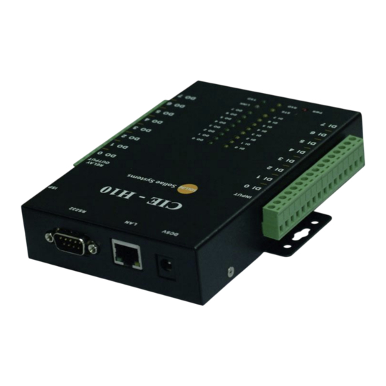
CIE-H10 User’s Manual Ver. 3.1 Macro mode Figure 1-5 macro mode Serial Device Server Figure 1-6 serial device server Components The CIE-H10’s body 5V Power Adapter RS232C Cable for PC (option) Adapter for DIN rail (option) ... -
Page 9: Specification
CIE-H10 User’s Manual Ver. 3.1 Specification 1.4.1 H/W specification Input Power 5V (±10%) Power Current Consumption 510mA typical Size 153mm x 126mm x 32mm Weight Approximately 530g ARM7 Core Digital Input 8 ports with photo couplers Digital Output 8 ports with relays... -
Page 10: Interface
Interface 1.5.1 Input Ports Because each of the CIE-H10’s input ports are isolated by photo-couplers, users don’t need to be worried about the polarity. The circuit of the input port is shown in the figure below. The [EXTERNAL INPUT1] and [EXTERNAL INPUT2] port should be interfaced with the user device. -
Page 11: Output Ports
CIE-H10 User’s Manual Ver. 3.1 1.5.2 Output Ports The output ports of the CIE-H10 are interfaced to relays as shown below. The [EXTERNAL OUTPUT1] and [EXTERNAL OUTPUT2] port should be interfaced with the user device. EXTERNAL OUTPUT1 EXTERNAL OUTPUT2 VCC_5V... -
Page 12: Rs232 Port (Db9M)
CIE-H10 User’s Manual Ver. 3.1 1.5.3 RS232 Port (DB9M) The CIE-H10 has an RS232 port supporting from 300 bps to 230,400 bps. This port is for connecting users’ serial devices to Ethernet (TCP/IP) including the “Serialized Modbus/TCP”. Pin Assignment... -
Page 13: Ethernet Interface
CIE-H10 User’s Manual Ver. 3.1 1.5.4 Ethernet Interface An RJ45 connector is for the network interface of the CIE-H10. You can use a UTP cable. It automatically senses 10Mbits or 100Mbits Ethernet. It also provides auto MDI/MDIX function that can automatically sense 1:1 cable or cross over cable. -
Page 14: System Led
There is an ISP switch located on the side of the product. It is a switch that will allow the CIE-H10 to be operated as serial configuration mode or ISP mode. If the switch is pressed between 20ms and 1s, the CIE-H10 changes the mode into the serial configuration mode. -
Page 15: Installation And Test
Figure 2-1 the connection between H10 and a PC 2.1.1 Setting Network Aera This step is for setting both the CIE-H10 and your PC to be located the same network. If only they are, the TCP connection between them can be established. - Page 16 MS Windows and this is comfortable to use because it doesn’t need installation process. First, search your CIE-H10 via network. All the values of parameters are set to the default values in the factory. To apply it to your system, proper values should be set via ezManager.
-
Page 17: Test Operation
Test operation 2.2.1 Modbus/TCP Test This is for checking the operation of Input and output ports of the CIE-H10 via Modbus/TCP. In this instruction, offered Modbus/TCP test program was used. Run ezManager. Then, you can show the window like the figure below. - Page 18 Modbus/TCP test Figure 2-4 Modbus/TCP test ① Input the IP address of the CIE-H10 ② Input the local port for Modbus/TCP of the CIE-H10 In a local area network, ① and ② steps can be omitted. ③ Try to connect by pressing [Connect] button ④...
-
Page 19: Http Test With A Web Browser
2.2.2 HTTP Test with a WEB browser This is for testing the operation of Input and output ports of the CIE-H10 via HTTP. The test was implemented with a WEB browser. You can use WEB browsers such as MS Internet Explorer, Google Chrome and Mozilla Firefox. -
Page 20: Configuration
3.1.1 Configuration via LAN Checklists Make sure of the connection between your PC and the CIE-H10 via Ethernet. If they are in the same network, [MAC Address search] button can be used. If they aren’t, only [IP Address search] is allowed to use. -
Page 21: Configuration Via Serial
3.1.2 Configuration via Serial Checklists Make sure of the connection between your PC and the CIE-H10 using a RS232 cross cable. The CIE-H10 has to be operating in the [Serial Configuration] mode. You make the CIE-H10 operates in the serial configuration mode by pressing the ISP- button less than 1 second. -
Page 22: At Command
In the AT command mode, you can change some parameters through the serial port. Checklists Make sure of the connection between your PC and the CIE-H10 using a RS232 cross cable. All the parameters of the serial port between the CIE-H10 and the Terminal of your PC should be the same. -
Page 23: Operation Modes
CIE-H10 User’s Manual Ver. 3.1 Operation Modes What is the Operation Mode? Each of three operation modes are designed for specific purposes, and those are as follows: Normal mode This mode is for normal data communication and has 5 different communication modes. -
Page 24: Comparison Of The Each Mode
Boolean Algebra. WEB(HTTP) Users can monitor and control the CIE-H10 via HTTP serial-Ethernet converter The CIE-H10 can be used as a serial-Ethernet converter. There are four communication modes in this operation. Table 4-3 comparison of four communication modes modifying... -
Page 25: Methods For I/O Control
CIE-H10 User’s Manual Ver. 3.1 Methods for I/O control MODBUS/TCP The CIE-H10 supports Modbus/TCP. By using this protocol, it remotely monitors and controls I/O devices. To use this method, users’ application should support this protocol. 5.1.1 Related Parameters Table 5-1 Modbus/TCP related parameters... -
Page 26: Modbus/Tcp Slave Mode
According to the standard Modbus/TCP users can use a Modbus/TCP manager to control and monitor their I/O devices. Like this standard, you can set the CIE-H10 to the [Slave] item to [Slave] mode. The [Passive] connection would be better than the [Active] in this mode and the [Peer Port] should be 502. -
Page 27: Tcp Connection Modes
I/O ports of the CIE-H10 through the RS232 port. Note that if you are using this mode, you can’t control the output ports of the CIE-H10 with HTTP or Modbus/TCP. And also, the TCP and UDP data communication for serial devices cannot be activated. -
Page 28: Macro Mode
CIE-H10 User’s Manual Ver. 3.1 Macro Mode This mode let users set the values of the output ports with simple macros. The CIE-H10 reflects the values according to the macro expressions which are configured by users in advance. It will be useful when users set the output values automatically from combinations of inputs. -
Page 29: Expression Example
CIE-H10 User’s Manual Ver. 3.1 5.3.3 Expression example Here are some examples. In the expressions, spaces between the two operands will be ignored. Table 5-5 an example of equation Perform OR for i0 and i1. i0 + i1 Spaces in between two operands may be ignored... -
Page 30: Web (Http)
If passwords for the CIE-H10 are designated, the following window will be popped up. Figure 5-1 authentication with password ① the CIE-H10 does not care the [User name]. (You don’t have to fill the box) ② [Password] should be the same with password which is set through the ezManager. -
Page 31: Uploading Users' Web Page
If you cannot use this function, you should upgrade the version of boot even though your CIE-H10 has the latest version of F/W. For more information about the upgrading boot, please refer to the “CIE-H10_upgrading Boot and F/W” document on the [Download] >>... -
Page 32: Communication Modes
TCP Server In this mode, the CIE-H10 functions as a TCP server. The CIE-H10 waits for a TCP connection from remote hosts. Once a host tries to connect to the CIE-H10, it responses to that request. After the connection is established, the CIE-H10 converts the raw data from the serial port to TCP/IP packets and sends the packets to the network and vice versa. -
Page 33: An Example
CIE-H10 User’s Manual Ver. 3.1 6.1.2 An Example An example as a TCP server Figure 6-1 TCP server Table 6-2 descriptions of each state Point State H10 is waiting for request segments of a TCP connection ① Remote host has sent a request (SYN) segment Processes of the connection ②... -
Page 34: Tcp Client
[Peer Address] and [Peer Port]. Under situation that the TCP server works fine with the specific port, the connection will be established. After then, the CIE-H10 converts the raw data from the serial port to TCP/IP data and sends them to the network and vice versa. -
Page 35: An Example
CIE-H10 User’s Manual Ver. 3.1 DNS IP Address [DNS IP Address] needs when users use host name instead of the IP address on the [Peer Port] parameter. 6.2.2 An Example An example of TCP client Figure 6-2 time chart for a situation that [Event Byte] is set to 0... - Page 36 In the TCP client mode, the [TCP Server] check option is activated. If you check this option, the CIE-H10 operates as the TCP server/client mode. In this mode, the CIE- H10 can establish a TCP connection both actively and passively without changing any setting.
- Page 37 CIE-H10 User’s Manual Ver. 3.1 Fig 6-4 time chart for activating [TCP Server] option Table 6-6 descriptions of each state Point State H10 is waiting for request segments of a TCP connection ① The connection has been established H10 is on line and processes of the disconnection ②...
-
Page 38: At Command
CIE-H10 User’s Manual Ver. 3.1 AT Command AT command is a mode which users control the CIE-H10 with AT command like controlling modem. In this mode, active and passive TCP connections are available. And users are allowed to configure some environmental parameters with extended commands. -
Page 39: Examples
Processes of the TCP connection ③ TCP connection has been established The CIE-H10 sends “CONNECT” message to the serial port Most of the response messages from the serial port of the CIE-H10 are omitted on above figure. Sollae Systems Co., Ltd. - Page 40 Processes of the TCP connection ② The TCP connection has been established. The CIE-H10 sends “CONNECT” message to the serial port. For more information about this, please refer to the “ATC mode” on the [Download] >> [Technical Documents] menu of our web site.
-
Page 41: Udp
[Block Size] means the size of a block in UDP mode. Its unit is byte. The size of bytes are come into the serial port, the CIE-H10 sends them as one block to the network. The maximum value could be 1460 bytes. -
Page 42: Examples
CIE-H10 User’s Manual Ver. 3.1 6.4.2 Examples Block Size: 5 bytes / Data Frame Interval: 1s (100 * 10ms) Figure 6-7 time chart for block size is 5 bytes and Data Frame Interval is 1s Table 6-10 descriptions of each state... - Page 43 ③ H10 updates host 2 to peer host H10 can communicate with remote host 2 The data “ABC”, “DE”, “FGH” are from the serial port of the CIE-H10 in the above figure. Sollae Systems Co., Ltd. - 42 -...
-
Page 44: System Management
Upgrading Firmware 7.1.1 Firmware Firmware is a type of software for operation of the CIE-H10. If there are needs for adding function or fixing bugs, the firmware will be modified and released. We recommend that users keep use the latest released firmware. - Page 45 CIE-H10 User’s Manual Ver. 3.1 Checking firmware file and Sending Figure 7-2 sending firmware file ① Check if the name and path of the firmware file are correct ② Click the [Send] button ③ Confirm the completed message Sollae Systems Co., Ltd.
-
Page 46: Changing Webpage
② Click the [Change F/W / HTML] button to run TFTP client ③ Select the [Change HTML] radio button ④ Input the IP address of the CIE-H10 to the [Local IP Address] text box ⑤ Press the [Open Firmware / HTML] button and choose the HTML file Sollae Systems Co., Ltd. - Page 47 CIE-H10 User’s Manual Ver. 3.1 Checking firmware file and Sending Figure 7-4 sending firmware file ① Check if the name and path of the firmware file are correct ② Click the [Send] button ③ Confirm the completed message Sollae Systems Co., Ltd.
-
Page 48: Status Monitoring
Status Monitoring 7.3.1 Using TELNET Once the [TELNET] option is activated, users can remotely log in to the CIE-H10. If a password is set, users should input the password. After then, messages from the CIE-H10 appear like the figure below. - Page 49 CIE-H10 User’s Manual Ver. 3.1 st sio “st sio” command displays the number of bytes for the serial port. Figure 7-7 “st sio” command st uptime “st uptime” command shows amount of time since H10 has booted up.
-
Page 50: Using Ezmanager
CIE-H10 User’s Manual Ver. 3.1 7.3.2 Using ezManager Status of the CIE-H10 can be monitored by [Status] button on ezManager. By using the [Refresh Every 1 Second] option in the status window, the status is automatically updated in every second. - Page 51 Password This text box is activated when the CIE-H10 has a password. If users want to close the TCP connection, this password has to be correctly filled. Refresh Every 1 Second.
-
Page 52: Additional Functions
The maximum length is 8 bytes of Alphabet or number. When you want to revoke all of these restrictions, change the mode of the CIE-H10 to the ISP mode. All restrictions are removable and communication with ezManager is revoked in the ISP mode. -
Page 53: Option Tab Functions
8.2 Option Tab Functions 8.2.1 Notify IP Change The CIE-H10 can be a TCP server even though it is assigned the IP address automatically. Using [Notify IP Change] function, it sends its IP address with the host name to the specific server. -
Page 54: Sending Mac Address
CIE-H10 User’s Manual Ver. 3.1 8.2.2 Sending MAC Address [Sending MAC Address] is a function that the CIE-H10 sends its MAC address to the remote host right after the connection is established. By using this function, a server can identify multiple devices with the information. - Page 55 Figure 8-4 debugging message window ① Pull down menu for selecting a network adapter ② Place for showing received debugging messages from the CIE-H10 over the network ③ Auto update to display the latest captured file on the screen of ②...
-
Page 56: Serial Port Tab Functions
RTS/CTS when the states are changed. 8.3.2 Disable TCP Transmission Delay - ② If you use this option, CIE-H10 sends the data from the serial port to Ethernet as quickly as possible. 8.3.3 Data Frame Interval - ③... -
Page 57: Tcp Server / Client Mode - ⑤
The CIE-H10 gives output values to the output ports after the amount of time has set in the [Delay]. If users set the value of [Delay] to 0, the CIE-H10 gives the output value to the output port immediately. The unit used for the [Delay] is 1ms. However, because the accuracy is only guaranteed in 10ms, the designated values are rounded down in units of 10ms. -
Page 58: Self-Test In Trouble
CIE-H10 User’s Manual Ver. 3.1 Self-Test in Trouble When users are in trouble with the CIE-H10, make sure of the following steps first. Searching problem with ezManager Confirming types of configuration utility The CIE-H10 can be configured by ezManager. -
Page 59: Connection Problem Over Modbus/Tcp
Under this circumstance, users should ask the person in charge of their network to release ports which will be used. (Ex: TCP 502, UDP 50005) Operation Mode A TCP connection is not possible when the CIE-H10 is operating in the ISP or Serial Configuration mode. Connection Mode To make a TCP connection, both a server (passive mode) and a client (active mode) should exist. -
Page 60: Communication Problem Over Modbus/Tcp
CIE-H10 User’s Manual Ver. 3.1 Communication Problem over Modbus/TCP Checking Modbus/TCP parameters Check all the related parameters that [Unit ID], [Input Port Base Address], [Output Port Base Address], [Poll Interval] and [Notify Input change]. Checking which mode is using In case of MACRO or serialized Modbus/TCP, you can control the outputs of the CIE- H10. -
Page 61: Technical Support, Warranty And Precaution
10 Technical Support, Warranty and Precaution 10.1 Technical Support If you have any question regarding operation of the product, visit Customer Support FAQ corner and the message board on Sollae Systems’ web site or send us an email at the following address: E-mail: support@eztcp.com... -
Page 62: Precaution
Do not use the product for a purpose that requires exceptional quality and reliability relating to user’s injuries or accidents – aerospace, aviation, health care, nuclear power, transportation, and safety purposes. Sollae Systems is not responsible for any accident or damage occurring while using the product. Sollae Systems Co., Ltd. -
Page 63: History
CIE-H10 User’s Manual Ver. 3.1 11 History Date Version Comment Author 2007.03.22 ○ Initial touch 2007.06.11 ○ Initial Release 2007.06.28 ○ Add Security Function 2007.06.29 ○ Correct Maximum Input Port Voltage 2007.07.16 ○ Change English Expressions by JJS 2007.09.03 ○ Add Telnet COM Port Control Option 2007.09.19... - Page 64 CIE-H10 User’s Manual Ver. 3.1 ○ The description of the CIE-H10 has been changed. 2010.08.30 Roy LEE ○ Major icons have been inserted on the front cover. ○ Descriptions about input/output ports have been added. 2011.01.20 ○ Diagram of “Macro mode” has been added.
Need help?
Do you have a question about the CIE-H10 and is the answer not in the manual?
Questions and answers