Table of Contents
Advertisement
Advertisement
Table of Contents

Related Manuals for Ridder RB50EPLUS


Summary of Contents for Ridder RB50EPLUS
- Page 1 Product Manual Ridder RB50Eᵖˡᵘˢ Tube motor Original Product Manual 265041EN - 2017.06 - V01 Ridder Drive Systems Lorentzstraat 36-38 3846 AX Harderwijk P.O. Box 360 3840 AJ Harderwijk the Netherlands T +31 (0)341 416 854 F +31 (0)341 416 611...
-
Page 2: Table Of Contents
8.2 Maintenance and cleaning RB50Eᵖˡᵘˢ tube motor and accessories 8.3 Maintenance and cleaning roller-screen system 9. SERVICE 9.1 Troubleshooting 9.2 Technical support 10. ENVIRONMENT 10.1 Waste disposal 10.2 Decommissioning and removal Ridder Drive Systems T +31 (0)341 416 854 F +31 (0)341 416 611 I www.ridder.com... -
Page 3: Guidelines, Standards And Conditions
1. GUIDELINES, STANDARDS AND CONDITIONS 1.1 Applicable guidelines and standards The Ridder RB50Eᵖˡᵘˢ tube motor complies with the provisions of the European guidelines that follow: Machinery Directive 2006/42/EC | Low Voltage Directive 2006/95/EC | EMC Directive 2004/108/EC The harmonized standards (or parts of these standards) that follow are applicable:... -
Page 4: Precautions And Safety Instructions
Work without professional competence or not obeyed warning instructions could cause injury and/or material damage. • Ridder is not responsible for injury, material damage or consequential damage if accessories that Ridder did not make are used. If you do not obey the safety instructions that follow it can be dangerous and cause injury. -
Page 5: Residual Risks
Because of the forces in the systems (in which the tube motor is installed), Ridder cannot be sure that there will be no injury to persons or damage to the system. -
Page 6: Product Details
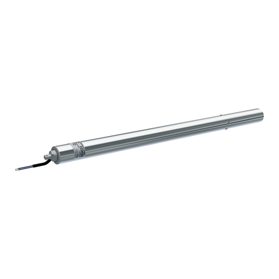
3.1 Description The Ridder RB50Eᵖˡᵘˢ tube motor is built-in to a 50 mm aluminium tube (wall thickness 1.5 mm) and suitable for use with 50 mm winding tubes. Because it is built-in it is possible to wind around the full width of the tube motor. -
Page 7: Application
Components RB50Eᵖˡᵘˢ tube motors To operate the roller-screen system more components are necessary to complete the drive system. The illustration and table that follow show an overview of the Ridder components that are applicable to the RB50Eᵖˡᵘˢ tube motor. Position Description RB50Eᵖˡᵘˢ... -
Page 8: Dimensions
Thermal protection < 120 °C (248 °F) Applicable for intermittent duty, duty class S2, a maximum of 10 Duty Cycle (kb) minutes Environment Protection rating IP55 Ridder Drive Systems T +31 (0)341 416 854 F +31 (0)341 416 611 I www.ridder.com... -
Page 9: Identification
Make sure that the correct equipment and tools are used. During mechanical installation an adjusting switch can be used, if necessary, to operate the tube motor. §7.2 gives more information about the adjusting switch. Ridder Drive Systems T +31 (0)341 416 854 F +31 (0)341 416 611 I www.ridder.com... -
Page 10: Installation - Conditions And Starting Points
Put the cable-carrier bracket (8) and tube motor (1) in the correct position for the related installation side of the roller screen. REFER TO §4.4/4.5. This prevents more subsequent work. Ridder Drive Systems T +31 (0)341 416 854 F +31 (0)341 416 611 I www.ridder.com... - Page 11 Sloped building-structure • If the building structure is sloped Ridder recommends to put the tube motor and guiding system at the highest position. This makes sure that water can flow away from the tube motor along the roller screen when it is winded up.
-
Page 12: Installation Guiding Profile And Guiding Unit
The highest point possible of the guiding unit (2) is related to the width of the purlin (A). Refer to illustration 4.3.4. Ridder Drive Systems T +31 (0)341 416 854 F +31 (0)341 416 611 I www.ridder.com... - Page 13 4.3.1 4.3.2 6.5mm (4x) 4.3.3 10.5 6.5 (4x) 19.5 4.3.4 Ridder Drive Systems T +31 (0)341 416 854 F +31 (0)341 416 611 I www.ridder.com...
- Page 14 Drill the holes at the correct positions for the related installation side of the roller screen. This prevents more subsequent work. REFER TO §4.4/4.5. 4.3.5 4.3.6 4.3.7 Ridder Drive Systems T +31 (0)341 416 854 F +31 (0)341 416 611 I www.ridder.com...
- Page 15 Make sure that the guiding unit (2) is put onto the guiding profile (3) before installation. REFER TO ILLUSTRATION 4.3.2. This prevents more subsequent work. 4.3.8 4.3.9 4.3.10 Ridder Drive Systems T +31 (0)341 416 854 F +31 (0)341 416 611 I www.ridder.com...
-
Page 16: Attach The Tube Motor To The Guiding Unit
6. Put the split pin (19) in the hole of ø 4mm. 7. Use the split pin (19) and safety the assembly. 4.4.1 (C-C) (C-C) Ridder Drive Systems T +31 (0)341 416 854 F +31 (0)341 416 611 I www.ridder.com... -
Page 17: Attach The Cable Carrier
3. Use the screws (7.1) or bolts (7.1) to install the cable-carrier mounting-bracket (7). 4. Use the pop-rivets (5) to attach the end connector (FCP) to the cable-carrier mounting-bracket (7). 4.5.2 Ridder Drive Systems T +31 (0)341 416 854 F +31 (0)341 416 611 I www.ridder.com... - Page 18 (6). Attach this end (6) to the end connector (MCP) at the cable-carrier bracket (8). 7. Attach the other end of the cable carrier (6) to the end connector (FCP) at the cable-carrier mounting-bracket (7). 4.5.3 Ridder Drive Systems T +31 (0)341 416 854 F +31 (0)341 416 611 I www.ridder.com...
-
Page 19: Attach The Coupling Piece To The Tube Motor
This distance is temporarily necessary when the cord (20.1) is pulled through the winding tube (17). Refer to step 2 of §4.7. 4.6.1 550037 (P20) *550039: <194 mm <120* Ridder Drive Systems T +31 (0)341 416 854 F +31 (0)341 416 611 I www.ridder.com... -
Page 20: Attach The Screen Cloth And Winding Tube
Compared to the winding tube (17), this tube does not have a groove for the screen cloth (20). • First attach the screen cloth (20) to the building structure. Make sure that it does not fold! Ridder Drive Systems T +31 (0)341 416 854 F +31 (0)341 416 611 I www.ridder.com... - Page 21 7. Use a pop-rivet pliers to attach the pop-rivet (18). 8. Drill the holes for the other three pop-rivets (18). 9. Use the pop-rivet pliers to attach the other three pop-rivets (18). 4.7.5 Ridder Drive Systems T +31 (0)341 416 854 F +31 (0)341 416 611 I www.ridder.com...
-
Page 22: Connect Instructions
• Do not connect other electrical equipment (lamps, relays and such) directly to the connection cables of the motor. • Isolate all poles, with a minimum contact separation of 3 mm per pole (EN 60335), from the mains voltage. Ridder Drive Systems T +31 (0)341 416 854 F +31 (0)341 416 611 I www.ridder.com... - Page 23 Parallel connection of RB50Eᵖˡᵘˢ tube motors with electronic limit-switch systems is possible. Always make sure that the load is less than the maximum switch-contact load for the switch installation (relay controls, switches and such). Ridder Drive Systems T +31 (0)341 416 854 F +31 (0)341 416 611 I www.ridder.com...
-
Page 24: Wiring Diagram: Single
(relay controls, switches and such). To change the direction-of-rotation of RB50Eᵖˡᵘˢ tube motor: Interchange the two phase wires (black and brown). Ridder Drive Systems T +31 (0)341 416 854 F +31 (0)341 416 611 I www.ridder.com... -
Page 25: Wiring Diagram: Parallel
(relay controls, switches and such). To change the direction-of-rotation of RB50Eᵖˡᵘˢ tube motor: Interchange the two phase wires (black and brown). Ridder Drive Systems T +31 (0)341 416 854 F +31 (0)341 416 611 I www.ridder.com... -
Page 26: User Instructions
If the maximum duty cycle is ignored this can cause malfunctions. Because of this the tube motor can become defective. Ridder Drive Systems T +31 (0)341 416 854 F +31 (0)341 416 611 I www.ridder.com... -
Page 27: Operation
• An RB50Eᵖˡᵘˢ tube motor can be operated by a Ridder MotorControl RMC50 control unit. • The primary use of Ridder RB50Eᵖˡᵘˢ tube motors will be in automated roller-screen systems. An RMC50 control unit is compatible with an Automatic Control System (ACS) to make operation together possible. -
Page 28: Special Tools And Equipment
The pulse counter makes sure that: • The tube motor stops at an end position • The tube motor stops (as a safety precaution) if there is an overload. Ridder Drive Systems T +31 (0)341 416 854 F +31 (0)341 416 611 I www.ridder.com... -
Page 29: Setting The End Positions
At this time the limit-switch system and the range of travel of the RB50Eᵖˡᵘˢ tube motor are set. Disconnect the tube motor from the adjusting switch. Connect the tube motor to the control box. Ridder Drive Systems T +31 (0)341 416 854 F +31 (0)341 416 611 I www.ridder.com... -
Page 30: Erasing One End Position
“double click”. Release the two buttons. Click - Click Obey the procedure in §7.4 to set the erased end position again! Ridder Drive Systems T +31 (0)341 416 854 F +31 (0)341 416 611 I www.ridder.com... -
Page 31: Erasing Two End Positions At The Same Time
“double click”. Release the two buttons. Click - Click Obey the procedure in §7.4 to set the erased end positions again! Ridder Drive Systems T +31 (0)341 416 854 F +31 (0)341 416 611 I www.ridder.com... -
Page 32: Maintenance Instructions
8.2 Maintenance and cleaning RB50Eᵖˡᵘˢ tube motor and accessories Minimum maintenance For the Ridder RB50Eᵖˡᵘˢ tube motor and accessories not much maintenance is necessary. But it is important that the user does regular checks for a correct operation of the tube motor and its components. -
Page 33: Service
Cause 6 1 thru 5 do not give a solution to the problem. The cause is unknown. Solution 6 Contact your supplier or the manufacturer. Ridder Drive Systems T +31 (0)341 416 854 F +31 (0)341 416 611 I www.ridder.com... -
Page 34: Technical Support
9.2 Technical support For technical support contact your local After Sales contact person. You can find your local After Sales contact person on our website at www.ridder.com. Ridder Drive Systems T +31 (0)341 416 854 F +31 (0)341 416 611 I www.ridder.com... -
Page 35: Environment
10. ENVIRONMENT 10.1 Waste disposal Discard products of Ridder Drive Systems after their lifespan and obey the applicable national and/ or local regulations. 10.2 Decommissioning and removal Decommissioning and removal is only permitted to approved personnel. Ridder Drive Systems T +31 (0)341 416 854 F +31 (0)341 416 611 I www.ridder.com... - Page 36 www.ridder.com...
Need help?
Do you have a question about the RB50EPLUS and is the answer not in the manual?
Questions and answers