Table of Contents
Advertisement
Operation Manual
You must read the Usage and Safety Precautions before use.
© 2019 ZOOM CORPORATION
Copying or reprinting this manual in part or in whole without permission is prohibited.
Product names, registered trademarks and company names in this document are the property of their respective companies. All trademarks and registered
trademarks in this document are for identification purposes only and are not intended to infringe on the copyrights of their respective owners.
Proper display is not possible on grayscale devices.
Advertisement
Table of Contents

Subscribe to Our Youtube Channel
Related Manuals for Zoom L-8 LiveTrack


Summary of Contents for Zoom L-8 LiveTrack
- Page 1 Operation Manual You must read the Usage and Safety Precautions before use. © 2019 ZOOM CORPORATION Copying or reprinting this manual in part or in whole without permission is prohibited. Product names, registered trademarks and company names in this document are the property of their respective companies. All trademarks and registered trademarks in this document are for identification purposes only and are not intended to infringe on the copyrights of their respective owners.
-
Page 2: Operation Manual Overview
Recording from copyrighted sources, including CDs, records, tapes, live performances, video works and broadcasts, without permission of the copyright holder for any purpose other than personal use is prohibited by law. Zoom Corporation will not assume any responsibility related to infringements of copyrights. -
Page 3: Introduction
Introduction Thank you very much for purchasing a ZOOM LiveTrak combines a compact digital mixer with a multitrack recorder and a USB audio interface, so it can be used for a variety of applications, including for podcasting and streaming, as a PA for small groups, as a live per- formance mixer, and for stage performances and music production. -
Page 4: Table Of Contents
Contents Operation Manual overview �������������� 2 Projects ������������������������ 66 Changing project names ���������������� 66 Introduction ����������������������� 3 Deleting projects ��������������������� 68 Contents ������������������������� 4 Protecting projects �������������������� 69 Checking project information ������������� 70 Names and functions of parts ������������ 5 Checking, deleting and moving to marks ������... -
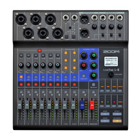
Page 5: Names And Functions Of Parts
Names and functions of parts Input channel section ⑩ LINE input jack ① MIC/LINE input jack ⑪ LINE input indicator ⑫ Smartphone connection indicator ⑬ USB indicator ⑭ INPUT SEL button ⑮ Smartphone connection jack ② 48V switch ③ −26dB switch ④... - Page 6 ④ Hi-Z switch Use to switch the input impedance of the MIC/LINE input jack (1 or 2). Turn it on ( ) when connecting a guitar or bass guitar. ⑤ GAIN knob Use to adjust the input gain of the mic preamp. The range of adjustment depends on the on/off status of the MIC/LINE input jack switch (Hi-Z on channels 1–2 or −26dB on channels 3–6).
- Page 7 ⑪ LINE input indicator This lights when the LINE input is enabled. ⑫ Smartphone connection indicator This lights when the Smartphone connection jack is enabled. ⑬ USB indicator This lights when the input of audio return signals output from a computer is enabled. ⑭...
-
Page 8: Channel Strip Section
CHANNEL STRIP section ① EFX knob ④ HIGH knob ⑤ MID knob ② PAN knob ⑥ LOW knob ③ LOW CUT button ① EFX knob The amount that can be sent to the EFX bus can be set from −∞ to +10 dB. ②... - Page 9 Send effect (SEND EFX) section ① EXT RTN MUTE button ② EFX RTN level meters ③ EFX RTN fader ① EXT RTN MUTE button This mutes or unmutes the signal sent from the built-in effect. To mute the signal, press this button to light it. ②...
-
Page 10: Output Section
Output section ② MASTER OUT PHONES jack ③ MASTER OUT PHONES knob ④ MONITOR OUT PHONES A–C jacks ① MASTER OUT XLR jacks ⑤ MONITOR OUT knobs A–C ⑥ MONITOR OUT A–C switches ⑦ MASTER REC/PLAY button ⑧ MASTER MUTE button ⑨... - Page 11 ⑤ MONITOR OUT knobs A–C Use to adjust the volumes of the signals output from the MONITOR OUT PHONES A–C jacks. ⑥ MONITOR OUT A–C switches These switch the signals output from the MONITOR OUT PHONES A–C jacks. Status Explanation MASTER The same signals as those output from the MASTER OUT jacks are output.
- Page 12 Display, function and mode section ① Display ② Selection encoder ③ Function buttons ④ MIXER mode button ⑥ EFFECT mode button ⑦ RECORDER mode button ⑤ SCENE mode button ① Display This shows the status of the selected mode and other information. ( → “Function buttons and display appear- ance in each mode”...
- Page 13 Function buttons and display appearance in each mode █ MIXER mode ① MASTER and MIX A–C buttons ⑤ SOUND PAD settings button ② MIX COPY button ③ MIX PASTE button ④ AUDIO I/F button ① MASTER and MIX A–C buttons The signal balance set using the channel faders can be switched as layers according to the outputs you want to show and adjust.
- Page 14 ① ② Item Explanation ① Selected mix This highlights the selected mix. ② Remaining battery charge This shows the remaining battery charge. When the remaining battery charge (when battery-powered) becomes low, replace the batteries or connect an AC adapter.
-
Page 15: Effect Mode
█ EFFECT mode ① Effect type buttons ① Effect type buttons The currently selected effect type appears lit. Press a button to change the effect. The selected effect will be shown on the display. Its parameters can be changed using the Selection encoder. ( →... - Page 16 █ SCENE mode ① 1–7 buttons ② RESET button ① 1–7 buttons Use these buttons to select the scene used to save the current mixer settings and to recall saved scenes. Press these buttons to open screens where SAVE, RECALL and CANCEL can be selected. ②...
- Page 17 █ RECORDER mode ② FF button ③ TEMPO button ④ SETTING button ① REW button ⑧ OVERDUB button ⑤ STOP button ⑥ PLAY button ⑦ REC button ① REW button Press to move to the previous mark. Press when at the beginning to move to the previous project. Press and hold to search backward. (The longer pressed, the faster the speed becomes.) ②...
- Page 18 ⑦ REC button This puts the recorder in recording standby. • During recording, it lights red. • When recording is paused, it blinks red. ⑧ OVERDUB button This sets whether recording is overdubbed in the current project or whether a new project is created and new recording conducted.
-
Page 19: Back
Back ① POWER switch ② SD card slot ① POWER switch This turns the power on and off. Switch to ON to turn the power on. Switch to OFF to turn the power off. When the POWER switch setting is changed to OFF, the current mixer settings are automatically saved in the and in the settings file in the project folder on the SD card. -
Page 20: Bottom
Bottom ① Micro USB port ② Battery compartment cover ① Micro USB port This Micro USB 2.0 port can be used to connect an AC adapter or computer. A mobile battery, for example, can also be connected to run on bus power. ②... -
Page 21: Equipment Connection Examples
Equipment connection examples Podcasting Mics with tabletop stands Headphones Computer Smartphone Bottom... -
Page 22: Live Pa System
Live PA system Vocal mic Drum mics Keyboard Electric bass Performer headphones Electric guitar When connecting a passive electric guitar or electric bass to channel 1 or 2, press switch. Operator Powered speakers headphones... -
Page 23: Preparations
Preparations Providing power Using an AC adapter Connect the cable of the dedicated AD-17 AC adapter to the Micro USB port. Bottom Plug the dedicated AC adapter into an outlet. HINT • When connected to a computer, power can be supplied by USB. •... -
Page 24: Using Batteries
Using batteries Open the battery compartment cover on the bottom of the product and insert 4 AA batteries. Replace the battery cover. NOTE • Use only one type of battery (alkaline, NiMH or lithium) at a time. • If the remaining battery power indicator drops to 0, turn the power off immediately and install new batteries. •... -
Page 25: Turning The Power On And Off
Turning the power on and off Turning the power on Input and output connectors GAIN knobs Channel, EFX RTN and MASTER faders POWER switch Confirm that the output devices connected to the are turned off. Confirm that is set to OFF. Set all knobs and faders to their minimum values. -
Page 26: Turning The Power Off
Connect instruments, mics, speakers and other equipment. HINT Equipment connection examples ( → “Equipment connection examples” on page to ON. Turn on the output devices connected to the NOTE on. ( → • When using a passive guitar or bass guitar, connect it to channel 1 or 2, and turn “Top”... -
Page 27: Using The Setting Screen
Using the SETTING screen Use the SETTING screen to make recorder function settings, for example. This is an explanation of the basic operations. Open the SETTING screen: Press , and then press This opens the SETTING screen. Select setting items and parameters: Turn This moves the cursor. -
Page 28: Mixer
Mixer Outputting input sounds from output devices MASTER OUT (PHONES) knob GAIN knobs and SIG indicators MUTE buttons Channel faders Master fader to adjust the input signals while inputting sound from instruments and mics. NOTE Set them so that the SIG indicators do not light red. SIG indicator Turn off (unlit) for the MASTER and the channels with sound you want to output. - Page 29 Switching channel 7 and 8 inputs Channels 7 and 8 can use the following inputs. LINE input Use the input jacks to connect line level equipment. For example, connect a keyboard or audio device. Smartphone input (channel 8 only) A smartphone can be input in stereo using channel 8. When podcasting, this enables input from a connected smartphone of guests participating remotely.
-
Page 30: Adjusting The Tone And Panning
Adjusting the tone and panning Channel strip section buttons To enable tone and panning adjustment on a channel, press to light it. Use the knobs and buttons in the channel strip section to adjust the tone and panning. Adjusting the tone: Adjusting the panning: HINT Details about each knob and button ( →... -
Page 31: Using The Built-In Effects
Using the built-in effects has 8 types of send effects that can be used in 1 effect channel. EFX knob Display Selection encoder SEL buttons EFX RETURN MUTE Function buttons button EFFECT mode button EFX RTN fader Press so that it lights. The currently selected effect type is shown on the display. - Page 32 to adjust the effect parameters. • Adjust parameter: Turn • Select parameter: Press NOTE are listed here ( → The parameters of each effect type that can be adjusted using “Send effect specifi- cations” on page 111).
-
Page 33: Using Scene Functions
Using scene functions Scene functions can be used to save up to 7 sets of current mixer settings as scenes and to recall these saved settings at any time. Display Selection encoder SCENE 1–7 buttons RESET button SCENE mode button ... - Page 34 NOTE • The can store 7 scenes. • If a button that already has a scene saved is selected, that scene will be overwritten. • The following items are saved with scenes. – Fader positions (each channel, EFX 1/2 RTN and MASTER) –...
- Page 35 Resetting mixer settings Press so that it lights. This opens the SCENE screen. Press Turn to select RECALL, and press The current mixer settings are reset to their factory defaults. To not reset the scene, turn , select CANCEL, and press...
-
Page 36: Setting Signals Output From Monitor Out A-C
Setting signals output from MONITOR OUT A–C The MONITOR OUT A–C jacks can be set to output the same mix as the MASTER OUT or different mixes. MONITOR OUT knobs MONITOR OUT switches Display Selection encoder MASTER and MIX A–C buttons MIX COPY button MIX PASTE button MIXER mode button... - Page 37 Adjusting the MONITOR OUT A–C volumes Turn for MONITOR OUT A–C. Selecting MONITOR OUT A–C output signals Use the MONITOR OUT switch for an output to select its output signal. Output mixes set with MIX A–C Output same mix as MASTER NOTE •...
- Page 38 Press This copies the mix from the source to the destination.
-
Page 39: Connecting Smartphones
Connecting smartphones has a smartphone connection jack. By connecting a smartphone to this jack using a 4-contact mini-plug (TRRS) cable, the audio signal from the smartphone can be input on channel 8. Moreover, the mix out- put signal can be input to the smartphone. This feature enables guests to participate in podcasts by phone. Smartphone Audio signal from mix output signal... -
Page 40: Recording And Playback
Recording and playback Preparing to record Inserting SD cards POWER switch SD card slot to OFF. Open the SD card slot cover, and insert an SD card all the way into the slot. To remove an SD card, push it further into the slot and then pull it out. NOTE •... - Page 41 Creating new projects manages recording and playback data in units called projects. Display Selection encoder SETTING button RECORDER mode button Press so that it lights. This opens the RECORDER screen. Press so that it lights. This opens the SETTING screen. to select PROJECT >...
-
Page 42: Recording/Overdubbing And Playing Recordings
Recording/overdubbing and playing recordings has recorder functions that enable simultaneous recording of up to 12 tracks and simultaneous play- back of up to 10 tracks. The input signals of each channel and the master fader output signal can be recorded and played. ... - Page 43 Press to stop recording. NOTE • The channel 7 and 8 recording tracks are stereo. • Punching in/out ( → “Redoing parts of recordings (punching in/out)” on page • Starting recording automatically ( → “Starting recording automatically” on page • Capturing audio before recording starts ( → “Pre-recording before recording starts”...
-
Page 44: Adding Marks
Adding marks Adding marks at desired positions with the recorder makes moving to those positions easy. Display Selection encoder FF button REW button RECORDER mode button Adding marks during recording and playback Press so that it lights. This opens the RECORDER screen. Press during recording/playback. -
Page 45: Redoing Parts Of Recordings (Punching In/Out)
Redoing parts of recordings (punching in/out) Punching in/out is a function that can be used to rerecord parts of already recorded tracks. "Punching in" is switching track status from playback to recording. "Punching out" is switching track status from recording to playback. -
Page 46: Mixing Down Tracks
Mixing down tracks A final stereo mix can be recorded to the master track. Signals are sent to the master track after passing through the master fader. Display MASTER REC/PLAY REW button button STOP button OVERDUB button REC button PLAY button RECORDER mode button ... - Page 47 Playing the master track Press so that it lights. This opens the RECORDER screen. Press the MASTER repeatedly until it lights green. Press NOTE • To stop master track playback, press MASTER repeatedly until it becomes unlit. • When the master track is playing, other tracks will not be played back. •...
-
Page 48: Starting Recording Automatically
Starting recording automatically Recording can be started and stopped automatically in response to the level after passing through the master fader. Display Selection encoder SETTING button REC button RECORDER mode button Master fader and level meters Press so that it lights. This opens the RECORDER screen. - Page 49 Press to light it and start recording standby. The MASTER level meters will blink at the level that will cause automatic recording to start. HINT Recording starts automatically when the input exceeds the set level (shown by the MASTER level meters). Recording can be set to stop automatically when the input goes below a set level.
-
Page 50: Pre-Recording Before Recording Starts
Pre-recording before recording starts Input signals can be captured for up to 2 seconds before recording is started (pre-recording). Setting this in advance can be useful when a performance starts suddenly, for example. Display Selection encoder SETTING button RECORDER mode button Press so that it lights. -
Page 51: Selecting Projects For Playback
Selecting projects for playback Projects saved on SD cards can be loaded. Display Selection encoder SETTING button RECORDER mode button Press so that it lights. This opens the RECORDER screen. Press so that it lights. This opens the SETTING screen. to select PROJECT >... -
Page 52: Sound Pad Functions
SOUND PAD functions Audio files (WAV format) can be assigned to the SOUND PAD 1-6 buttons. Press one to play the assigned file. The level and playback method can be set for each pad. These are useful, for example, for playing effect sounds dur- ing podcasting and streaming as well as during live theater and music performances. -
Page 53: Assigning Audio Files To Sound Pad Buttons
Assigning audio files to SOUND PAD buttons Built-in sounds and audio files saved on an SD card can be assigned to SOUND PAD buttons. Moreover, the can record sounds directly for assignment to SOUND PAD buttons. (The MASTER mix sound is recorded.) Display Selection encoder SOUND PAD settings button... - Page 54 Turn to select the SOUND PAD (1–6) for sound file assignment, and press HINT A SOUND PAD can also be selected for audio file assignment by pressing it. Turn to select SOUND ASSIGN, and press To assign a built-in sound: Turn to select PRESET SOUND, and press To assign an audio file stored on an SD card:...
- Page 55 Directly recording and assigning sounds to SOUND PAD buttons Press so that it lights. This opens the MIXER screen. Press so that it lights. This opens the SOUND PAD screen. Turn to select the SOUND PAD (1–6) for sound file assignment, and press HINT A SOUND PAD can also be selected for audio file assignment by pressing it.
- Page 56 NOTE • The recorded audio file is saved to the “SOUND_PAD” folder with a name that combines the pad number, date and a sequential number. (File name example: P1_0101_001.WAV) • Up to 1000 can be saved. • The sample rate of the audio file depends on the sample rate set on the •...
-
Page 57: Changing Sound Pad Playback Methods
Changing SOUND PAD playback methods For each SOUND PAD, the sound playback method used when it is pressed can be changed. Display Selection encoder SOUND PAD settings button MIXER mode button Press so that it lights. This opens the MIXER screen. Press so that it lights. - Page 58 Turn to select the playback method, and press Setting Explanation Press the SOUND PAD to play the file once to its end and then stop. ONE SHOT Press the SOUND PAD during playback to restart playback from the beginning. Pressing the pad alternately starts and stops playback. Loop playback will continue LOOP until stopped.
-
Page 59: Changing Sound Pad Playback Levels
Changing SOUND PAD playback levels For each SOUND PAD, volume levels used when it is pressed can be changed. Display Selection encoder SOUND PAD settings button MIXER mode button Press so that it lights. This opens the MIXER screen. Press so that it lights. - Page 60 Turn to adjust the volume, and press The audio level can be set to −∞ or in a range from −48.0 to +10.0 dB (in 0.5dB increments).
-
Page 61: Metronome
Metronome metronome has adjustable volume, a selectable sound, and a precount function. The volume can also be adjusted separately for each output. Metronome settings are saved separately with each project. Enabling the metronome Display Selection encoder SETTING button RECORDER mode button Press so that it lights. -
Page 62: Changing Metronome Settings
Changing metronome settings Display Selection encoder SETTING button TEMPO button PLAY button RECORDER mode button Changing the metronome tempo Press so that it lights. This opens the RECORDER screen. Press so that it lights. The current tempo is shown on the display. Do one of the following to change the tempo. - Page 63 Press so that it lights. This opens the SETTING screen. to select METRONOME > PRE COUNT. Turn to select the precount behavior, and press Setting Explanation No precount will sound. 1–8 Before recording/playback, the precount will sound for the set number of times (1–8). Before recording/playback, the precount will sound as shown below.
- Page 64 HINT The options are BELL, CLICK, STICK, COWBELL and HI-Q. NOTE to play the metronome and check the sound. Changing the metronome pattern Press so that it lights. This opens the RECORDER screen. Press so that it lights. This opens the SETTING screen. to select METRONOME >...
- Page 65 to select METRONOME > LEVEL > MASTER or MONITOR OUT A–C. Turn to adjust the volume, and press HINT Set from 0 to 100. NOTE Press to play the metronome and check the volume.
-
Page 66: Projects
Projects manages recording and playback data in units called projects. The following data is saved in projects. • Audio data • Mixer settings • Send return effect settings • Mark information • Metronome settings Changing project names The name of the currently loaded project can be changed. Display Selection encoder SETTING button... - Page 67 NOTE • The default project name is the date and time of creation. For example, if a project was created at 6:48:20 p.m. on Thursday, March 14, 2019, the project name would be "190314_184820" (YYMMDD_HHMMSS). • Project names have 13 characters. •...
-
Page 68: Deleting Projects
Deleting projects Projects inside the selected folder can be deleted. Display Selection encoder SETTING button RECORDER mode button Press so that it lights. This opens the RECORDER screen. Press so that it lights. This opens the SETTING screen. to select PROJECT > DELETE. Turn to select the project you want to delete, and press Turn... -
Page 69: Protecting Projects
Protecting projects The currently loaded project can be write-protected, preventing the project from being saved, deleted or having its content changed. Display Selection encoder SETTING button RECORDER mode button Press so that it lights. This opens the RECORDER screen. Press so that it lights. -
Page 70: Checking Project Information
Checking project information Various information about the currently loaded project can be viewed. Display Selection encoder SETTING button RECORDER mode button Press so that it lights. This opens the RECORDER screen. Press so that it lights. This opens the SETTING screen. to select PROJECT. -
Page 71: Checking, Deleting And Moving To Marks
Checking, deleting and moving to marks A list of marks in the currently loaded project can be opened, allowing them to be checked, moved to and deleted. Display Selection encoder SETTING button REC button RECORDER mode button Press so that it lights. This opens the RECORDER screen. -
Page 72: Audio Files
Audio files creates the following types of audio files according to the recording channel. • Channels 1–6: mono WAV files • Channels 7, 8 and MASTER: stereo WAV files The file format depends on the sampling rate ( → “Changing the sampling rate” on page 97) and quantization bit depth ( →... - Page 73 Turn to select the file to delete, and press Turn to select YES, and press NOTE Audio files cannot be deleted if protection is ON for their projects.
-
Page 74: Assigning Audio Files To Tracks
Assigning audio files to tracks Audio files can be imported from projects or elsewhere to existing projects and assigned to channels. NOTE • To load audio files from an SD card, first use a computer to store the files on the card in any directory other than the PROJECT folder. - Page 75 to select the file to assign, and press • To assign from a project: select PROJECT > the project that has the file to assign • To assign a file from the SD card: select SD CARD (WAV) Turn to select the file to assign, and press HINT Audio files can be auditioned by selecting them and pressing Turn...
-
Page 76: Audio Interface
Download the "ZOOM L-8 Driver" from www.zoom.co.jp to the computer. NOTE • The latest "ZOOM L-8 Driver” can be downloaded from the above website. • Download the driver for the operating system that you are using. Launch the installer and install the driver. -
Page 77: Connecting To A Computer
Connecting to a computer Display Selection encoder AUDIO I/F button MIXER mode button POWER switch Use a USB cable to connect the Micro USB port to a computer. Bottom to ON. Press so that it lights. This opens the MIXER screen. Press so that it lights. - Page 78 Turn to select PC/Mac, and press Setting Explanation PC/Mac Select this when connected to a Windows PC or Mac. Select this when connected to an iOS device or other type of class-compliant device. NOTE PC/Mac will be selected when the power is turned on. This setting is not saved. Turn to select YES, and press Select the...
-
Page 79: Connecting To An Ios Device
Connecting to an iOS device Display Selection encoder AUDIO I/F button MIXER mode button POWER switch to ON. Press so that it lights. This opens the MIXER screen. Press so that it lights. This opens the AUDIO I/F screen. Turn to select iOS, and press Setting Explanation... - Page 80 Turn to select YES, and press Use a USB cable to connect the iOS device to the Micro USB port. Bottom NOTE When connecting to an iOS device, use a Lightning to USB camera adapter (or Lightning to USB 3 camera adapter).
-
Page 81: Inputting Return Signals From The Computer On Channels 7/8
Inputting return signals from the computer on channels 7/8 USB indicators INPUT SEL buttons Press on the channel used for input, lighting The signal input on the channel is switched to the USB audio channel signal (before EQ). -
Page 82: Card Reader
Card reader SD card folder structure The folder structure on SD cards used by the is as follows. PROJECT folder This folder stores projects created by the This is a project created by the . The folder name will be the same as the name of the created project. -
Page 83: Using Card Reader Functions
Using card reader functions When connected to a computer, data on the SD card can be checked and copied. Display Selection encoder SETTING button RECORDER mode button POWER switch Use a USB cable to connect the Micro USB port to a computer. Bottom to ON. - Page 84 Turn to select YES, and press NOTE When operating as a CARD READER, other functions and buttons cannot be used.
-
Page 85: Recording And Playback Settings
Recording and playback settings Changing the recording format The recording format can be changed in consideration of audio quality and file size. Display Selection encoder SETTING button RECORDER mode button Press so that it lights. This opens the RECORDER screen. Press so that it lights. -
Page 86: Changing Automatic Recording Settings
Changing automatic recording settings The conditions for automatically starting and stopping recording can be set. Display Selection encoder SETTING button RECORDER mode button Setting the automatic recording start level Press so that it lights. This opens the RECORDER screen. Press so that it lights. - Page 87 Setting automatic stopping Press so that it lights. This opens the RECORDER screen. Press so that it lights. This opens the SETTING screen. to open REC/PLAY > AUTO REC > AUTO STOP. Turn to select the automatic stopping time, and press HINT This can be set to OFF or between 0 and 5 seconds.
-
Page 88: Showing Recording Levels On Level Meters
Showing recording levels on level meters The levels of signals recorded to the recorder can be shown on the level meters of each channel. Display Selection encoder SETTING button RECORDER mode button Press so that it lights. This opens the RECORDER screen. Press so that it lights. -
Page 89: Compensating For Latency During Input And Output
Compensating for latency during input and output can compensate for latency that occurs during input and output if you want to listen to its output signal while overdubbing. Use this menu item to set whether the latency that occurs during input and output is automatically compensated for or not when OVERDUB is ON. -
Page 90: Changing The Playback Mode
Changing the playback mode Display Selection encoder SETTING button RECORDER mode button Press so that it lights. This opens the RECORDER screen. Press so that it lights. This opens the SETTING screen. to open REC/PLAY > PLAY MODE. Turn to select the play mode, and press Setting Explanation Only the selected project plays back. -
Page 91: Sd Card Settings
SD card settings Checking the open space on SD cards Display Selection encoder SETTING button RECORDER mode button Press so that it lights. This opens the RECORDER screen. Press so that it lights. This opens the SETTING screen. to open SD CARD > REMAIN. This shows the open space on the card. -
Page 92: Formatting Sd Cards
Formatting SD cards Formatting SD cards for use with the Display Selection encoder SETTING button RECORDER mode button Press so that it lights. This opens the RECORDER screen. Press so that it lights. This opens the SETTING screen. to open SD CARD > FORMAT. Turn to select YES, and press NOTE... -
Page 93: Testing Sd Card Performance
Testing SD card performance SD cards can be tested to confirm whether they can be used with the A basic test can be done quickly, while a full test examines the entire SD card. Display Selection encoder SETTING button RECORDER mode button Conducting a quick test Press so that it lights. - Page 94 The result of the test will be shown when it completes. Press anytime to stop the test. NOTE Even if a performance test result is "OK", there is no guarantee that writing errors will not occur. This informa- tion is just to provide guidance. ...
- Page 95 The result of the test will be shown when it completes. If the access rate MAX reaches 100%, the card will fail (NG). Press anytime to stop the test. NOTE Even if a performance test result is "OK", there is no guarantee that writing errors will not occur. This informa- tion is just to provide guidance.
-
Page 96: Making Various Settings
Making various settings Setting the date and time Display Selection encoder SETTING button RECORDER mode button Press so that it lights. This opens the RECORDER screen. Press so that it lights. This opens the SETTING screen. to select SYSTEM > DATE/TIME. Setting the date and time •... -
Page 97: Changing The Sampling Rate
Changing the sampling rate The file format used when recording to the recorder depends on this setting. Display Selection encoder SETTING button RECORDER mode button Press so that it lights. This opens the RECORDER screen. Press so that it lights. This opens the SETTING screen. -
Page 98: Disabling The Automatic Power Saving Function
Disabling the automatic power saving function The power will automatically turn off if the is unused for 10 hours. To keep the power on at all times, disable the automatic power saving function. Display Selection encoder SETTING button RECORDER mode button Press so that it lights. -
Page 99: Adjusting The Display Contrast
Adjusting the display contrast Display Selection encoder SETTING button RECORDER mode button Press so that it lights. This opens the RECORDER screen. Press so that it lights. This opens the SETTING screen. to select SYSTEM > LCD CONTRAST. Turn to select the setting value, and press HINT This can be set from 1 to 10. -
Page 100: Setting The Display Backlight
Setting the display backlight Display Selection encoder SETTING button RECORDER mode button Press so that it lights. This opens the RECORDER screen. Press so that it lights. This opens the SETTING screen. to select SYSTEM > LCD BACKLIGHT. Turn to select the setting value, and press Setting Explanation Backlight always lit... -
Page 101: Setting The Type Of Batteries Used
Setting the type of batteries used Set the type of battery used correctly so that the amount of remaining battery charge can be shown accurately. Display Selection encoder SETTING button RECORDER mode button Press so that it lights. This opens the RECORDER screen. Press so that it lights. -
Page 102: Setting The Battery Saving Mode
Setting the battery saving mode To prevent battery consumption during operation on batteries, indicator and button illumination can be dimmed after 15 seconds without operation. Display Selection encoder SETTING button RECORDER mode button Press so that it lights. This opens the RECORDER screen. Press so that it lights. -
Page 103: Restoring Settings To Factory Defaults
Restoring settings to factory defaults The factory default settings can be restored. Display Selection encoder SETTING button RECORDER mode button Press so that it lights. This opens the RECORDER screen. Press so that it lights. This opens the SETTING screen. to select SYSTEM >... -
Page 104: Checking The Firmware Versions
Checking the firmware versions firmware versions can be viewed. Display Selection encoder SETTING button RECORDER mode button Press so that it lights. This opens the RECORDER screen. Press so that it lights. This opens the SETTING screen. to select SYSTEM > VERSION. This shows the firmware versions. -
Page 105: Updating The Firmware
POWER switch Copy the firmware update file to the root directory on an SD card. NOTE Files for the latest firmware updates can be downloaded from the ZOOM website (www.zoom.co.jp). Insert the SD card into the While pressing (SOUND PAD), set to ON. - Page 106 After the firmware update completes, turn the off. NOTE In the unlikely event that a firmware update should fail while in progress, conduct the procedures from the beginning to update the firmware again.
-
Page 107: Troubleshooting
“Formatting SD cards” on page • If formatting an SD card does not improve this, we recommend replacing the card. Please check the list of cards that have been confirmed to work on the ZOOM website. NOTE This list is provided as a guideline to help find suitable cards. It is not a guarantee of specific SD card recording... - Page 108 Playback sound cannot be heard or is quiet • When playing data from an SD card, confirm that is lit green. • Raise the faders on the playback channels, and confirm that the level meters are lit. The sounds of devices connected to input jacks are distorted •...
- Page 109 • Confirm that the is connected to the computer correctly. • Confirm that the Sound setting of the computer being used is set to "ZOOM L-8". • Confirm that is set for input and output in the software that you are using.
-
Page 110: Specifications
LCD with backlight (96×64 resolution) Power 4 AA batteries (alkaline, lithium, or rechargeable NiMH) AC adapter (ZOOM AD-17): DC 5V/1A Supports USB bus power Estimated continuous recording time using batteries Recording 44.1kHz/16-bit/4ch audio to SD card (when 48V is OFF, LCD BACKLIGHT is 15sec, BATTERY SAVING is ON and headphone impedance is 62Ω):... -
Page 111: Send Effect Specifications
Send effect specifications Type Explanation Parameter 1 Parameter 2 Tempo sync Hall 1 Hall reverb with a bright tone TONE DECAY Hall 2 Hall reverb with a long time for early reflections TONE DECAY Room Dense room reverb TONE DECAY Plate Plate reverb simulation TONE... -
Page 112: Mixer Block Diagram
Mixer block diagram... - Page 113 ZOOM CORPORATION 4-4-3 Kanda-surugadai, Chiyoda-ku, Tokyo 101-0062 Japan www.zoom.co.jp Z2I-3814-01...
Need help?
Do you have a question about the L-8 LiveTrack and is the answer not in the manual?
Questions and answers