Advertisement
Quick Links
Advertisement

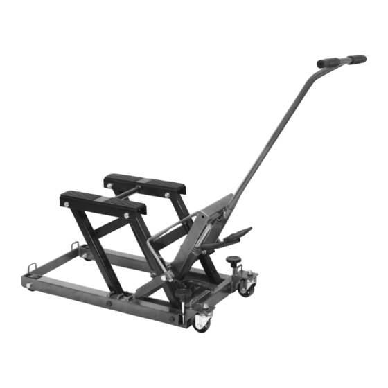
Summary of Contents for Black Widow BW-0101
-
Page 2: Table Of Contents
Table of contents Safety ............2 Maintenance ..........9 Specifications ..........3 Troubleshooting ......... 10 Setup ............3 Parts Lists and Assembly Diagrams ..12 Operation ............ 8 Warranty ............ 16 WARNING SyMbOLS AND DEFINITIONS This is the safety alert symbol. It is used to alert you to potential personal injury hazards. -
Page 3: Specifications
25. The warnings, precautions, and instructions 26. The brass components of this product contain lead, discussed in this manual cannot cover all a chemical known to the State of California to cause possible conditions and situations that may occur. cancer, birth defects (or other reproductive harm). The operator must understand that common sense (California Health &... - Page 4 Setup – before Use (continued) Lift Set Up Mounting the bottle Jack 1. Secure the Jack Assembly (30) to the Jack Mounting Plate portion of the Bottom Base (13) with two Bolts (23). See Figure B. bolt (23) bottle Jack (30) Jack Mounting plate bottom base (13) Figure b...
- Page 5 Installing the Stop bar connecting Rod 1. Insert the two ends of the Stop Bar Connecting Rod (40) into the sleeves on the Right and Left Stop Bars (41, 44). 2. Secure the Stop Bar Connecting Rod in place with two Nuts (42). See Figure D. Stop bar connecting Rod (40) Left Stop bar (44) Right Stop bar (41)
- Page 6 Setup – before Use (continued) Installing the Handle 1. Insert the end of the Handle (34) into the handle socket on the top of the Lifting Frame (36). 2. Secure the Handle in place with the Handle Pin (29) and Cotter Pin (32). See Figure F. Handle (34) Lifting Frame (36) cotter pin (32)
- Page 7 bleeding IMpORTANT! before first use, check for proper 3. While holding the Release Pedal down, hydraulic fluid level in the bottle Jack (30). Then quickly pump the Foot Pedal (27) up and down thoroughly test the Lift for proper operation several times to purge air from the system.
-
Page 8: Operation
Operating Instructions TO pREVENT SERIOUS INJURy: Do not work on the Lift, or leave it unattended if the Stop bars (41, 44) are not in the locked position, or the Lock bolts (16) are not engaged (lifting the Rear Wheels [17] off of the ground). Keep clear of Lift Arms (8, 43) during operation. Lifting 1. -
Page 9: Maintenance
Maintenance and Servicing procedures not specifically explained in this manual must be performed only by a qualified technician. TO pREVENT SERIOUS INJURy FROM TOOL FAILURE: Do not use damaged equipment. If abnormal noise or vibration occurs, have the problem corrected before further use. cleaning, Maintenance, and Lubrication 1. -
Page 10: Troubleshooting
Troubleshooting TO pREVENT SERIOUS INJURy: Use caution when troubleshooting a malfunctioning lift. Stay well clear of the supported load. completely resolve all problems before use. If the solutions presented in the Troubleshooting guide do not solve the problem, have a qualified technician inspect and repair the Lift before use. - Page 11 pLEASE READ THE FOLLOWING cAREFULLy THE MANUFACTURER AND/OR DISTRIBUTOR HAS PROVIDED THE PARTS LIST AND ASSEMBLY DIAGRAM IN THIS MANUAL AS A REFERENCE TOOL ONLY. NEITHER THE MANUFACTURER OR DISTRIBUTOR MAKES ANY REPRESENTATION OR WARRANTY OF ANY KIND TO THE BUYER THAT HE OR SHE IS QUALIFIED TO MAKE ANY REPAIRS TO THE PRODUCT, OR THAT HE OR SHE IS QUALIFIED TO REPLACE ANY PARTS OF THE PRODUCT.
-
Page 12: Parts Lists And Assembly Diagrams
parts Lists and Assembly Diagrams Main parts List part Description part Description Nylon Ring Bolt M8 x 3 0 Lift Saddle Spring Rubber Pad Bolt Rubber Pad Washer Foot Pedal Washer Foot Pedal Bolt M8 x 1 6 Handle Pin Front Lift Arm Bottle Jack Cotter Pin Washer... - Page 13 Main Assembly Diagram Page 13...
- Page 14 parts List A – bottle Jack (30) part Description part Description Ram Cap 24a Spring Plunger Ram O-Ring 25a Spring Top Sealing Gasket 26a Screw Ram Assembly 27a O-Ring Retaining Ring 28a Screw Piston Head 29a Screw Ram Gasket 30a Sealing Ring O-Ring 31a Spring Cylinder...
- Page 15 Assembly Diagram A – bottle Jack (30) Page 15...


Need help?
Do you have a question about the BW-0101 and is the answer not in the manual?
Questions and answers