Table of Contents
Advertisement
Quick Links
Operating Instructions
Functional Manual
DIGITAL LINK Switcher
Commercial Use
ET-YFB200G
Model No.
Thank you for purchasing this Panasonic product.
■ Before operating this product, please read the instructions carefully and save this manual
for future use.
■ Before using this product, be sure to read "Read this first!" (
pages 4 to 8).
TQBH0389-1
Advertisement
Table of Contents

Related Manuals for Panasonic ET-YFB200G


Summary of Contents for Panasonic ET-YFB200G
-
Page 1: Operating Instructions
Commercial Use ET-YFB200G Model No. Thank you for purchasing this Panasonic product. ■ Before operating this product, please read the instructions carefully and save this manual for future use. ■ Before using this product, be sure to read “Read this first!” ( pages 4 to 8). -
Page 2: Table Of Contents
Contents Contents Read this first! [INPUT SELECT] menu Switching the input [PICTURE] menu Chapter 1 Preparation [SYSTEM SELECTOR] [CLAMP POSITION] Precautions for use [DIGITAL CINEMA REALITY] Cautions when transporting [POSITION] menu Cautions when installing [SHIFT] DIGITAL LINK [CLOCK PHASE] Early Warning Software Disposal [OVER SCAN] [ASPECT]... -
Page 3: English
Contents Technical information PJLink protocol Control commands via LAN <SERIAL IN> terminal <REMOTE IN> terminal Compatible signals Specifications Dimensions Index ENGLISH - 3... -
Page 4: Read This First
Read this first! Read this first! WARNING: THIS APPARATUS MUST BE EARTHED. WARNING: 1. Remove the plug from the mains socket when this unit is not in use for a prolonged period of time. 2. To prevent electric shock, do not remove cover. No user serviceable parts inside. Refer servicing to qualified service personnel. - Page 5 To assure continued compliance, follow the attached installation instructions and use only shielded interface cables when connecting to computer and/or peripheral devices. Any changes or modifications not expressly approved by Panasonic Corp. of North America could void the user’s authority to operate this device. ENGLISH - 5...
- Page 6 L or coloured RED. How to replace the fuse: Open the fuse compartment with a screwdriver and replace the fuse. Importer’s name and address within the European Union Panasonic Marketing Europe GmbH Panasonic Testing Centre Winsbergring 15, 22525 Hamburg, Germany...
- Page 7 Read this first! WARNING: r POWER The wall outlet or the circuit breaker shall be installed near the equipment and shall be easily accessible when problems occur. If the following problems occur, cut off the power supply immediately. Continued use of the device in these conditions will result in fire or electric shock. f If foreign objects or water get inside the device, cut off the power supply.
- Page 8 Read this first! WARNING: Do not allow metal objects, flammable objects, or liquids to enter inside of the device. Do not allow the device to get wet. Doing so may cause short circuits or overheating, and result in fire, electric shock, or malfunction of the device. f Do not place containers of liquid or metal objects near the device.
- Page 9 rTrademarks f Windows, Windows Vista, and Internet Explorer are registered trademarks or trademarks of Microsoft Corporation in the United States and other countries. f Mac, macOS, OS X, and Safari are trademarks of Apple Inc., registered in the United States and other countries.
- Page 10 ▶ This device is also supporting the “long reach”, which is the communication method unique to Panasonic that can extend the transmission distance with the equipment connected with the DIGITAL LINK, and transmission up to 150 m (492'1") is possible when connecting with a display that can perform the long reach communication.
-
Page 11: Chapter 1 Preparation
Preparation Chapter 1 This chapter describes things you need to know or check before using this device. ENGLISH - 11... -
Page 12: Precautions For Use
Chapter 1 Preparation — Precautions for use Precautions for use Cautions when transporting f When transporting this device, avoid excessive vibration and impacts. Failure to do so may cause damage to internal components and result in malfunctions. Cautions when installing rDo not set up the device outdoors. The device is designed for indoor use only. -
Page 13: Digital Link
Panasonic Corporation, and not all the operations have been verified. For operation or performance problems caused by the devices of other manufacturers, contact the respective manufacturer. -
Page 14: Accessories
Chapter 1 Preparation — Precautions for use Accessories Make sure that the following accessories are provided with your device. Numbers enclosed in < > show the number of accessories. AC adapter <1> Rack mounting bracket <2> (CF-AA6373A or CF-AA6413A) (TKZX5287) Power cord <3> Foot <4>... -
Page 15: Optional Accessories
Chapter 1 Preparation — Precautions for use Contents of the supplied CD-ROM The content of the supplied CD-ROM is as follows. Instruction (PDF) Operating Instructions – Functional Manual Optional accessories Optional accessories Model No. (product name) D-SUB - S Video conversion ET-ADSV cable Early Warning Software... -
Page 16: About Your Device
Chapter 1 Preparation — About your device About your device Main body Front Side Rear Bottom Control panel (x page 17) AC adapter securing bracket mounting screw hole (x page 30) Rack mounting bracket mounting screw holes (x page 20) Connecting terminals (x page 18) These are used when mounting the device to a rack. -
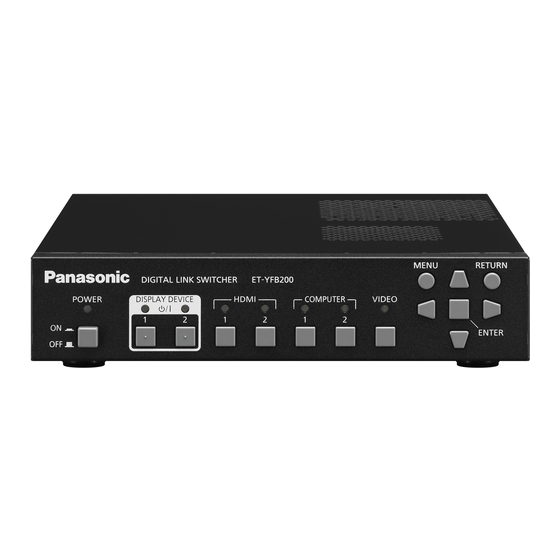
Page 17: Control Panel
Chapter 1 Preparation — About your device r Control panel Power indicator <POWER> Input terminal indicator Lights in green when the power of the device is on. Lights off Lights in green when it is selected. when the power is turned off. <HDMI 1>... - Page 18 Chapter 1 Preparation — About your device r Connecting terminals <REMOTE IN> terminal <COMPUTER 1 IN> terminal This is a terminal to remotely operate the device via the external This is a terminal to input RGB signal, Y/C signal, or YC control circuit.
-
Page 19: Chapter 2 Getting Started
Getting Started Chapter 2 This chapter describes things you need to do before using this device, such as the setup and connections. ENGLISH - 19... -
Page 20: Setting Up
Chapter 2 Getting Started — Setting up Setting up Mounting on a rack This device can be mounted on the EIA standard (ANSI/EIA-310-D) compliant rack. Rack mounting brackets Rack mounting bracket mounting screw holes (3 locations each on either sides) Attach the supplied rack mounting brackets. f Align the supplied rack mounting brackets to either sides of the device and secure them tightly with 6 supplied screws (M3x6). - Page 21 Chapter 2 Getting Started — Setting up Attention f When placing the device on a desk or on a shelf, always use the feet. When buttons on the control panel are pressed, the device may slip and cause a flaw on the table or the shelf. f Always turn off the power when attaching the feet to the device.
-
Page 22: Connecting
Chapter 2 Getting Started — Connecting Connecting Before connecting f Before connecting, carefully read the Operating Instructions of the equipment to be connected. f Turn off the power of all devices before connecting cables. f Take note of the following points before connecting the cables. Failure to do so may result in malfunctions. g When connecting the cable to this device or to the equipment to be connected with this device, touch a metal object around you to discharge the static from your body before holding the cable. -
Page 23: Connecting Example: Image Input Device And Audio Device
Chapter 2 Getting Started — Connecting <HDMI 1 IN> terminal/<HDMI 2 IN> terminal pin assignment and signal name Outside view Pin No. Signal name Pin No. Signal name T.M.D.S data 2+ (11) T.M.D.S clock shield T.M.D.S data 2 shield (12) T.M.D.S clock- Odd-numbered pins of (1) to (19) T.M.D.S data 2- (13) -
Page 24: Connecting Example: Computers
Chapter 2 Getting Started — Connecting Note f For an HDMI cable, use an HDMI High Speed cable that conforms to HDMI standards. If a cable that does not conform to HDMI standards is used, images may be interrupted or may not be displayed. f The <HDMI 1 IN>... - Page 25 LAN communication. Note that the usage exceeding the maximum transferable distance is not covered by the Panasonic support. Depending on the display to be connected, there may be limit in the signal or the distance that the display can receive.
- Page 26 Chapter 2 Getting Started — Connecting When performing cascade connection for this device By connecting the devices with cascade connection (multiple device connection) using the HDMI/DVI conversion cable, video signal can be output to 3 or more DIGITAL LINK compatible displays (projector or flat panel display). DIGITAL LINK compatible projector DIGITAL LINK compatible flat panel display DIGITAL LINK compatible projector...
- Page 27 The <DVI-D OUT> terminal can connect to the HDMI and DVI-D compliant devices. However, this may not properly display as no image is output on some devices. Using a twisted-pair-cable transmitter of other manufacturers When connecting with a Panasonic non-DIGITAL LINK compatible display (projector or flat panel display), use a twisted-pair-cable transmitter (receiver) of other manufacturers based on the HDBaseT standard.
- Page 28 Panasonic website ((https://panasonic.net/cns/projector/) or (https://panasonic.net/cns/prodisplays/)). Note that the confirmation of operation for devices of other manufacturers has been performed only with the items set by Panasonic Corporation, and not all the operations have been verified. For operation or performance problems caused by the devices of other manufacturers, contact the respective manufacturer.
-
Page 29: Chapter 3 Basic Operations
Basic Operations Chapter 3 This chapter describes basic operations to start with. ENGLISH - 29... -
Page 30: Turning On/Off The Device
Chapter 3 Basic Operations — Turning on/off the device Turning on/off the device Connecting the AC adapter Confirm that the <POWER> button of the device is in the <OFF> condition before connecting the AC adapter and the power cord. For detailed handing of the AC adapter and the power cord, refer to “Read this first!” (x page 4). Attaching procedure <DC IN>... -
Page 31: Turning On The Power Of The Digital Link Switcher
Chapter 3 Basic Operations — Turning on/off the device Attention f Do not attach the power cord and the AC adapter with the front side of the device down. f Be sure to fix the cables connected to the device and the supplied AC adapter nearby such as the legs of the desk to avoid the cable and AC adapter weights directly applied to the device. -
Page 32: Turning On/Off The Power Of The Display
Chapter 3 Basic Operations — Turning on/off the power of the display Turning on/off the power of the display The power of the display (projector or flat panel display) connected to the <DIGITAL LINK OUT 1> terminal or the <DIGITAL LINK OUT 2> terminal of the device can be turned off/on with the <DISPLAY DEVICE v/b 1> button or the <DISPLAY DEVICE v/b 2>... -
Page 33: Turning On The Power Of The Display
Chapter 3 Basic Operations — Turning on/off the power of the display g Power of the flat panel display is turned on. g Control with the DIGITAL LINK terminal or the LAN terminal is enabled. g RS-232C communication via the twisted-pair-cable transmitter is enabled. g Control for the response is enabled when the “ID ALL”... -
Page 34: Checking The Image
Chapter 3 Basic Operations — Checking the image Checking the image Confirm the connection of the external equipment (x page 22), connection of the AC adapter (x page 30), and then turn on the power. (x page 31) Select an image, and confirm that the selected image is projected from the projector or displayed on the flat panel display. -
Page 35: Operating With The Remote Control
Chapter 3 Basic Operations — Operating with the remote control Operating with the remote control This device can be operated with the remote control of the display when the display (projector or flat panel display) is connected to the <DIGITAL LINK OUT 1> terminal/<DIGITAL LINK OUT 2> terminal. Depending on the remote control, it may not have some buttons or operations may be different. - Page 36 Chapter 3 Basic Operations — Operating with the remote control How to display the on-screen menu (main menu) when the projector is used Press the DIGITAL LINK button on the remote control. f The [INPUT SELECT] menu of this device is displayed. Press the MENU button or the RETURN button on the remote control.
-
Page 37: Chapter 4 Settings
Settings Chapter 4 This chapter describes the settings and adjustments you can make using the on-screen menu. ENGLISH - 37... -
Page 38: Menu Navigation
Chapter 4 Settings — Menu navigation Menu navigation The on-screen menu (menu screen) is used to perform various settings and adjustments of this device. Navigating through the menu Operating procedure button Press the <MENU> button on the control panel. f The main menu screen is displayed. ET-YFB200 DIGITAL LINK SWITCHER HDMI 1... -
Page 39: Main Menu
Chapter 4 Settings — Menu navigation f When 3D signal is output from the device, the menu of the device is not displayed. To change the setting of the device, input the 2D signal or operate without inputting any signal. f When 3D signal is output from the device, all the setting items in the [PICTURE] menu and the [POSITION] menu are disabled. f The cursor color depends on the setting in the [OPTION] menu →... - Page 40 Chapter 4 Settings — Menu navigation [PICTURE] Sub-menu item Factory default Page [SYSTEM SELECTOR] [AUTO] [CLAMP POSITION] [24] [DIGITAL CINEMA REALITY] [AUTO] *1 Depends on the signal input. Note f The factory default settings may vary depending on the picture mode. f Displaying of sub-menu items and factory default values differ depending on the selected input terminal.
-
Page 41: [Input Select] Menu
Chapter 4 Settings — [INPUT SELECT] menu [INPUT SELECT] menu Select [INPUT SELECT] from the main menu in the menu screen, and display the sub-menu. Refer to “Navigating through the menu” (x page 38) for the operation of the menu screen. Switching the input An input terminal for the image can be selected. -
Page 42: [Picture] Menu
Chapter 4 Settings — [PICTURE] menu [PICTURE] menu Select [PICTURE] from the main menu, and select the item from the sub-menu. Refer to “Navigating through the menu” (x page 38) for the operation of the menu screen. f After selecting the item, press asqw to adjust. Note f All the setting items in the [PICTURE] menu are disabled when 3D signal is output from the device. -
Page 43: [Digital Cinema Reality]
Chapter 4 Settings — [PICTURE] menu [DIGITAL CINEMA REALITY] The vertical resolution is further raised with the cinema process to enhance the picture quality when 576i signal is input to PAL (or SECAM), and 480i, 1080/50i, or 1080/60i signal is input to NTSC. Press as to select [DIGITAL CINEMA REALITY]. -
Page 44: [Position] Menu
Chapter 4 Settings — [POSITION] menu [POSITION] menu Select [POSITION] from the main menu, and select the item from the sub-menu. Refer to “Navigating through the menu” (x page 38) for the operation of the menu screen. f After selecting the item, press asqw to adjust. f Setting value of each item in the [POSITION] is reflected to all the video signals output from the <DVI-D OUT>... -
Page 45: [Over Scan]
Chapter 4 Settings — [POSITION] menu f Optimal value may not be achieved when there is a shift in the total dot numbers. f [CLOCK PHASE] can be adjusted only when the signal is input to the <COMPUTER 1 IN> terminal or the <COMPUTER 2 IN> terminal. However, [CLOCK PHASE] cannot be selected when Y/C signal, YC signal (480i, 576i), or analog RGB signal (480i, 576i) is input. - Page 46 Chapter 4 Settings — [POSITION] menu Press the <ENTER> button. f The [INPUT RESOLUTION] individual adjustment screen is displayed. Press as to select [TOTAL DOTS], [DISPLAY DOTS], [TOTAL LINES], or [DISPLAY LINES], and press qw to adjust each item. f Values corresponding to the input signal are displayed automatically for each item. Increase or decrease the displayed values and adjust to the optimal condition viewing the screen when there is a vertical banding or missing in the screen.
-
Page 47: [Language] Menu
Chapter 4 Settings — [LANGUAGE] menu [LANGUAGE] menu On the menu screen, select [LANGUAGE] from the main menu, and display the sub-menu. Refer to “Navigating through the menu” (x page 38) for the operation of the menu screen. Changing the display language Select the language of the on-screen display. -
Page 48: [Option] Menu
Chapter 4 Settings — [OPTION] menu [OPTION] menu Select [OPTION] from the main menu, and select the item from the sub-menu. Refer to “Navigating through the menu” (x page 38) for the operation of the menu screen. f After selecting the item, press asqw to adjust. [ON-SCREEN SETTING] Set the on-screen display. - Page 49 Chapter 4 Settings — [OPTION] menu Press the <ENTER> button. f The [COMPUTER IN] screen is displayed. Press as to select [COMPUTER 1 INPUT SETTING]. Press qw to switch items. f The item is switched every time the button is pressed. Select this when the RGB signal or the YC signal is input to the <COMPUTER 1 IN>...
-
Page 50: [Hdmi In]
Chapter 4 Settings — [OPTION] menu Press the <RETURN> button. f The screen returns to the [COMPUTER IN] screen. 10) Press as to select [VERTICAL SCAN FREQUENCY]. 11) Press the <ENTER> button. f The [VERTICAL SCAN FREQUENCY] screen is displayed. 12) Press as to select [VERTICAL SCAN FREQUENCY]. f When [1920x1080p] is selected for [RESOLUTION], select [60Hz], [50Hz], [30Hz], [25Hz], or [24Hz]. - Page 51 Chapter 4 Settings — [OPTION] menu Press the <ENTER> button. Press the <RETURN> button. f The screen returns to the [HDMI IN] screen. 10) Press as to select [VERTICAL SCAN FREQUENCY]. 11) Press the <ENTER> button. f The [VERTICAL SCAN FREQUENCY] screen is displayed. 12) Press as to select [VERTICAL SCAN FREQUENCY].
-
Page 52: [Digital Link Out]
Chapter 4 Settings — [OPTION] menu [DIGITAL LINK OUT] Perform the setting of the output signal from the <DIGITAL LINK OUT 1> terminal and the <DIGITAL LINK OUT 2> terminal. Press as to select [DIGITAL LINK OUT]. Press the <ENTER> button. f The [DIGITAL LINK OUT] screen is displayed. -
Page 53: [Dvi-D Out]
Chapter 4 Settings — [OPTION] menu [DVI-D OUT] Perform the setting of the output signal from the <DVI-D OUT> terminal. Press as to select [DVI-D OUT]. Press the <ENTER> button. f The [DVI-D OUT] screen is displayed. Press as to select [FRAME LOCK]. Press qw to switch items. -
Page 54: [Closed Caption Setting]
Chapter 4 Settings — [OPTION] menu Press the <ENTER> button. f The [DVI-D OUT] screen is displayed. Press as to select [CASCADE]. Press qw to switch items. f The item is switched every time the button is pressed. [OFF] Does not output the audio signal from the <DVI-D OUT> terminal. [ON] Outputs the audio signal superimposed on the video signal from the <DVI-D OUT>... -
Page 55: [Back Color]
Chapter 4 Settings — [OPTION] menu [BACK COLOR] The color of the output image when the video signal is not input in the selected input terminal is set. Press as to select [BACK COLOR]. Press qw to switch the item. f The item is switched every time the button is pressed. [BLUE] Outputs a video signal with blue on full area. - Page 56 Chapter 4 Settings — [OPTION] menu Adjusting the audio balance Adjust the balance of the audio output from the <AUDIO OUT> terminal. Press as to select [AUDIO SETTING]. Press the <ENTER> button. f The [AUDIO SETTING] screen is displayed. Press as to select [BALANCE]. Press qw to adjust the level.
-
Page 57: [Auto Setup]
Chapter 4 Settings — [OPTION] menu Outputs the audio from the <HDMI 2 IN> terminal when a video signal is input to the selected input [HDMI 2 AUDIO IN] terminal. f This is displayed only when [HDMI 2] is selected in Step 5). Outputs the audio from the <AUDIO IN 1>... -
Page 58: Rs-232C]
Chapter 4 Settings — [OPTION] menu Enables the backup function and switches to the secondary input automatically when the input signal for primary input is disrupted. Primary input is fixed to the <HDMI 2 IN> terminal, and the secondary input is fixed to the <HDMI 1 IN>... - Page 59 Chapter 4 Settings — [OPTION] menu Press the <ENTER> button. f The [RS-232C] screen is displayed. Press as to select [(IN)PARITY]. Press qw to switch items. f The item is switched every time the button is pressed. [NONE] [EVEN] Sets the condition of parity. [ODD] Setting [(OUT)PARITY] Set the communication condition for the <DIGITAL LINK OUT 1>...
-
Page 60: [Network]
Chapter 4 Settings — [OPTION] menu [DISABLE] Does not control the device by command when the “ID ALL” command is received. [ENABLE] Controls the device by command when the “ID ALL” command is received. Setting [GROUP] Set the group of this device. Control of the device by command is performed when the ID designation in the command matches. -
Page 61: [Status]
Chapter 4 Settings — [OPTION] menu [SUBNET MASK] Enter the subnet mask when a DHCP server is not used. [DEFAULT GATEWAY] Enter the default gateway address when a DHCP server is not used. [STORE] Saves the current network setting. Press as to select [STORE], and press the <ENTER> button. Note f If a DHCP server is to be used, confirm that the DHCP server is running. -
Page 62: [Initialize]
Chapter 4 Settings — [OPTION] menu Press the <ENTER> button. f The [STATUS] screen is displayed. [NAME] Displays the input signal name. [INPUT SIGNAL] [FREQUENCY] Displays the frequency of the input signal. [NAME] Displays the output signal name. [OUTPUT SIGNAL] [FREQUENCY] Displays the frequency of the output signal. -
Page 63: Chapter 5 Network Control Function
Network control Chapter 5 function This chapter describes the network control function. ENGLISH - 63... -
Page 64: Network Connection
Chapter 5 Network control function — Network connection Network connection This device is equipped with a network function, and following are possible by connecting with a computer. f Web control Setting, adjustment, and status display of this device are possible by accessing this device from a computer. For details, refer to “Using the web control function”... -
Page 65: Setting Of The Device
LAN communication. Note that the usage exceeding the maximum transferable distance is not covered by the Panasonic support. Depending on the display to be connected, there may be limit in the signal or the distance that the display can receive. -
Page 66: Using The Web Control Function
Enter the IP address set on this device in the URL entry field of the web browser. Enter the user name and the password. f The factory default setting is as follows: User name: user1 (user rights)/admin1 (administrator rights), password: panasonic (lower case) Click OK. f The [Switcher status] screen is displayed. - Page 67 Chapter 5 Network control function — Using the web control function Description of items Page tab [Detailed set up] Click this item to switch pages. Click this item to display the [Detailed set up] page. [Status] [Change password] Click this item to display the status of this device. Click this item to display the [Change password] page.
- Page 68 Chapter 5 Network control function — Using the web control function [Network status] page Click [Status] → [Network status]. Display the current network setting information. [Access error] page Click [Status] → [Access error]. Error information of the Web server, such as access to a page that does not exist or access with illegal user name or illegal password, is displayed.
- Page 69 Chapter 5 Network control function — Using the web control function [Switcher control] page Click [Switcher control]. [INPUT SELECT] [CLOSED CAPTION] Switches the input signal. Switches the setting for the closed caption. [VOLUME] [POSITION] Adjusts the volume output from the <AUDIO OUT> terminal. Operates the items regarding the angle of image.
- Page 70 Chapter 5 Network control function — Using the web control function subsequent operation is not guaranteed, so click [Network config] again. f The communication may be disconnected when the LAN setting is changed while connected with the LAN. [Ping test] page Confirm that the network is connected with the DNS server, etc.
- Page 71 Chapter 5 Network control function — Using the web control function [Change password] page Click [Change password]. [Administrator] [Next] Select to change the setting of [Administrator]. Displays the screen to change the password setting. [User] Select to change the setting of [User]. [Administrator] [Account] [New]...
- Page 72 Chapter 5 Network control function — Using the web control function [User] [Account] [OK] Displays the account to change. Determines the change of password. [New] [User name]: Enter a new user name. (Up to 16 characters in single byte) [Password]: Enter a new password. (Up to 16 characters in single byte) [Password(Retype)]: Enter the new password again.
-
Page 73: Using The Browser Remote Control
Enter the user name and the password for the web control. f The factory default setting is as follows: User name: user1 (user rights)/admin1 (administrator rights), password: panasonic (lower case characters) Click OK. f The browser remote control screen (operation panel) is displayed. -
Page 74: Description Of Items
Chapter 5 Network control function — Using the browser remote control Description of items Display device indicator [INPUT SELECT] Displays the status of the power of the display (projector or Switches the input signal. Status of the select/deselect can be flat panel display) connected to the <DIGITAL LINK OUT 1> confirmed at the indicator. -
Page 75: Chapter 6 Appendix
Appendix Chapter 6 This chapter describes specifications and after-sales service for the device. ENGLISH - 75... -
Page 76: Maintenance
Chapter 6 Appendix — Maintenance Maintenance The air intake ports and the air exhaust ports at the top and sides of the device may get clogged with dirt or dust after long period of usage. Clean the air intake ports/air exhaust ports periodically. Before maintenance f Always turn off the power before maintenance. -
Page 77: Troubleshooting
Chapter 6 Appendix — Troubleshooting Troubleshooting Review the following points. For details, see the corresponding pages. Problems Points to be checked Page f Is the power plug firmly inserted into the outlet? ― f Is the power connector firmly inserted into the AC adapter? ―... -
Page 78: Frequently Asked Questions
Chapter 6 Appendix — Frequently Asked Questions Frequently Asked Questions Check the following. Video is not displayed across the entire screen when HDMI signals are input from a computer. Perform the following two steps. f Adjust the aspect ratio of screens output by a computer to suit pixels (aspect ratio) of the display (projector or flat panel display). (Ex.: When the pixels of the display are 1 024 x 768 dots (4:3), set the resolution of the screen on the computer to 800 x 600 dots (4:3).) f Set [ASPECT] to [FULL]. -
Page 79: Technical Information
Chapter 6 Appendix — Technical information Technical information PJLink protocol The network function of the device supports PJLink Class 1, and PJLink protocol can be used to perform setting of this device and the display (projector or flat panel display) and status query from a computer. Connection r When connecting to the DIGITAL LINK compatible display Control computer... -
Page 80: Control Commands Via Lan
Generate a 32-byte hash value from the following data using MD5 algorithm. f “xxxxxx:yyyyy:zzzzzzzz” xxxxxx Administrator rights user name for the web control (default user name is “admin1”) yyyyy Password of above administrator rights user (default password is “panasonic”) zzzzzzzz 8-byte random number obtained in Step 2) 80 - ENGLISH... - Page 81 Chapter 6 Appendix — Technical information Command transmission method Transmit using the following command formats. r Transmitted data Termination Header Data section symbol Command Hash value ‘0’ ‘0’ Control command (CR) example “Connecting” (x page 80) 0x30 0x30 (ASCII string) 0x0d Data length 32 bytes 1 byte...
- Page 82 Chapter 6 Appendix — Technical information Command transmission method Transmit using the following command formats. r Transmitted data Termination Header Data section symbol Command ‘0’ ‘0’ Control command (CR) example 0x30 0x30 (ASCII string) 0x0d Data length 1 byte 1 byte Undefined length 1 byte f Example: Transmission of power supply status acquisition command...
-
Page 83: Serial In> Terminal
Chapter 6 Appendix — Technical information <SERIAL IN> terminal The <SERIAL IN> terminal on this device is a terminal to externally control the device and the display (projector or flat panel display) connected via the <DIGITAL LINK OUT 1> terminal/<DIGITAL LINK OUT 2> terminal. This is used to be connected to the serial terminal (RS-232C compliant) of the control computer using the supplied Plug for 3-pin 3.5 mm detachable terminal block. - Page 84 Chapter 6 Appendix — Technical information Pin assignments and signal names 3-pin 3.5 mm removable terminal block Pin No. Signal name Details Outside view Transmitted data Received data Earth Communication conditions (Factory default) Signal level RS-232C-compliant Sync. method Asynchronous Baud rate 9 600 bps Parity None...
- Page 85 Chapter 6 Appendix — Technical information Attention f The response may be delayed or command may not be executed when a command is transmitted right after the power of the device is turned on. Try sending or receiving any command after 30 seconds. f When transmitting multiple commands, be sure to wait until 0.5 seconds has elapsed after receiving the response from the device before sending the next command.
-
Page 86: Cable Specification
Chapter 6 Appendix — Technical information Cable specification Prepare a cable to connect the <SERIAL IN> terminal of this device and the serial terminal (RS-232C compliant) of the control computer using the supplied Plug for 3-pin 3.5 mm detachable terminal block. Creation of a cable when the serial terminal of the computer is D-Sub 9-pin (male) is described here as an example. -
Page 87: Remote In> Terminal
Chapter 6 Appendix — Technical information Note f For the control command of the display (projector or flat panel display) connected to this device, refer to the Operating Instruction of the display in use. <REMOTE IN> terminal By using the <REMOTE IN> terminal of the device, it is possible to remotely control (contact control) the device from the control panel installed in different location when the remote control signal cannot reach the display (projector or flat panel display). -
Page 88: Compatible Signals
Chapter 6 Appendix — Technical information Compatible signals List of compatible signals (input) The following are the video signals supported by the input of this device. f Symbols that indicate formats are as follows. g V: VIDEO, Y/C g R: RGB g Y: YC g H: HDMI Scanning freq. - Page 89 Chapter 6 Appendix — Technical information Scanning freq. Plug and play Dot clock Resolution Compatible signal freq. Format Horizontal Vertical COMPUTER 1/ (Dots) HDMI 1/HDMI 2 (MHz) (kHz) (Hz) COMPUTER 2 MAC21 1 152 x 870 68.7 75.1 100.0 1 280 x 720 37.1 49.8 60.5...
- Page 90 Chapter 6 Appendix — Technical information List of compatible signals (output) The following are video signals supported by this device. The output resolution will differ depending on the input signal, frame lock setting, and output resolution setting. f Symbol that indicates format is as follows. The compatible signals for the <DIGITAL LINK OUT 1> terminal/<DIGITAL LINK OUT 2>...
-
Page 91: Specifications
Chapter 6 Appendix — Specifications Specifications The specifications of this device are as follows. Power supply 16 V = (16 V Direct Current) (DC Input terminal) 32 W (when power supply is “off”: 0.15 W) Power consumption (including the supplied AC adapter) Input: AC 100 V - 240 V, 1.5 A - 0.8 A, 50 Hz/60 Hz CF-AA6373A Output: DC 16 V, 3.75 A... - Page 92 Chapter 6 Appendix — Specifications r Applicable scanning frequency For details of the video signal supported by this device, refer to “Compatible signals” (x page 88). Video signal Horizontal 15.73 kHz, Vertical 59.94 Hz (NTSC/NTSC4.43/PAL-M/PAL60) Horizontal 15.63 kHz, Vertical 50 Hz (PAL/PAL-N/SECAM) Y/C signal Horizontal 15.6 kHz to 98.8 kHz, Vertical 24.0 Hz to 120.0 Hz RGB signal...
- Page 93 Chapter 6 Appendix — Specifications r Terminal 2 sets, high-density D-Sub 15 p (female) RGB signal 0.7 V [p-p] 75 Ω (SYNC ON GREEN: 1.0 V [p-p] 75 Ω) HD/SYNC TTL high impedance, automatic positive/negative polarity compatible <COMPUTER 1 IN> terminal/<COMPUTER 2 IN> TTL high impedance, automatic positive/negative terminal polarity compatible...
-
Page 94: Dimensions
Chapter 6 Appendix — Dimensions Dimensions Unit: mm Front Front 210 (8-9/32") r When mounting a rack Front 10.3 (13/32") Front 127.5 (5-1/32") 210 (8-9/32") 127.5 (5-1/32") (465 (18-5/16")) 482 (18-31/32") 94 - ENGLISH... - Page 95 Chapter 6 Appendix — Dimensions r When placing on a desk or a shelf Front Front 20 (25/32") 170 (6-11/16") 197.2 (7-3/4") 37 (1-15/32") ENGLISH - 95...
-
Page 96: Index
Index Index Optional accessories [OVER SCAN] AC adapter Accessories [ASPECT] [PICTURE] 40, 42 <AUDIO IN 1> terminal [POSITION] 40, 44 <AUDIO IN 2> terminal <POWER> button 17, 31 <AUDIO IN 3> terminal Power cord <AUDIO OUT> terminal Power indicator [AUDIO SETTING] Precautions for use [AUTO SETUP] Read this first! - Page 97 Atıkların atılmasıyla ilgili yanlış uygulamalar yasayla belirlenmiş olan cezalara sebebiyet verebilir. Panasonic Corporation Web Site : https://panasonic.net/cns/projector/ © Panasonic Corporation 2015 Panasonic System Solutions Company of North America Two Riverfront Plaza, Newark, NJ 07102 TEL: (877) 803 - 8492 Panasonic Canada Inc.
Need help?
Do you have a question about the ET-YFB200G and is the answer not in the manual?
Questions and answers