Table of Contents
Advertisement
Quick Links
HC Heating controller
Manual for the
specialised craftsman
Mounting
Connection
Operation
Troubleshooting
Application examples
en
Thank you for buying this RESOL product.
Manual
Please read this manual carefully to get the best performance from this unit.
Please keep this manual carefully.
www.resol.com
Advertisement
Table of Contents

Related Manuals for Resol HC


Summary of Contents for Resol HC
- Page 1 HC Heating controller Manual for the specialised craftsman Mounting Connection Operation Troubleshooting Application examples Thank you for buying this RESOL product. Manual Please read this manual carefully to get the best performance from this unit. Please keep this manual carefully. www.resol.com...
- Page 2 • ATTENTION means that damage to the appli- CE mark. The Declaration of Conformity ance can occur. is available upon request, please contact RESOL. Note Strong electromagnetic fields can impair the function of the controller. Î Make sure the controller as well as the system are not exposed to strong elec- tromagnetic fields.
-
Page 3: Table Of Contents
HC Heating controller Contents Overview ............ 4 Arrangement ........... 43 Installation ..........5 7.1 Optional functions ..........43 2.1 Mounting ..............5 HQM ............52 2.2 Electrical connection ..........6 Basic settings ........... 53 10 SD card ............ 53 2.3 Data communication / Bus ........7 11 Manual mode .......... -
Page 4: Overview
Standby power consumption: < 1W circuit Mode of operation: type 1.B.C.Y • DHW heating Rated impulse voltage: 2,5 kV Interfaces: RESOL VBus , SD card slot ® • Circulation (with EM extension module) Functions: weather-compensated heating circuit • Thermal disinfection (with EM extension... -
Page 5: Installation
Installation In order to mount the device to the wall, carry out WARNING! Electric shock! the following steps: Upon opening the housing, live parts are exposed! Î Unscrew the cross-head screw from the cover and remove it along with the cover from the Î... -
Page 6: Electrical Connection
Electrical connection Note Temperature sensors (S1 to S9) have to be con- nected to the terminals S1 ... S9 and GND (either po- Connecting the device to the power supply WARNING! Electric shock! larity). must always be the last step of the instal- Upon opening the housing, live parts lation! The terminal S9 can be used as an impulse input for a... -
Page 7: Data Communication / Bus
Data communication / Bus SD card slot The controller is equipped with the RESOL VBus The controller is equipped with ® for data transfer with and energy supply to external an SD card slot. modules. The connection is carried out at the two ter- With an SD card, the following minals marked VBus and GND (either polarity). -
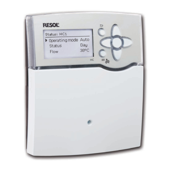
Page 8: Operation And Function
Operation and function Selecting menu points and adjusting values Buttons During normal operation of the controller, the display The controller is operated via the 7 buttons next to is in the main menu. If no button is pressed for a few the display. - Page 9 adjusted value adjustment channel (not yet confi rmed) If more than one item of several can be selected, they active area inactive area will be indicated with checkboxes. When an item has When 2 values are locked against each other, they will been selected, an x appears inside the checkbox.
- Page 10 Adjusting the timer Adding a time frame: The time frames can be adjusted in steps of 15 min- When the Timer option is activated, a timer is in- utes. dicated in which time frames for the function can be In order to add an active time frame, proceed as fol- adjusted.
- Page 11 Removing a time frame: In order to remove an active time frame, proceed as follows: Î Determine the point from which on the time frame is to be removed by pressing button Î Move the cursor to the desired ending point of the time frame by pressing buttons Î...
-
Page 12: Commissioning
1. Language: Commissioning Î Adjust the desired menu language. Initial commissioning When the hydraulic system is fi lled and ready for op- eration, connect the controller to the mains. The controller runs an initialisation phase in which the directional pad fl ashes red. When the controller is commissioned for the fi rst 2. -
Page 13: Schemes With Basic Settings
If the security enquiry has been confi rmed, the 3. Daylight savings time adjustment: controller is ready for operation and should en- Î Activate or deactivate the automatic daylight sav- able an optimum system operation. ings time adjustment. All adjustments made during commissioning can, if necessary, be changed later on in the basic settings menu. - Page 14 Scheme 1: one mixed heating circuit Sensors Relay outputs Flow HC1 1 / GND PWM/0-10V IP20 Outdoor 2 / GND Temperature sensors Free 3 / GND L' L Free 4 / GND Free 5 / GND Free 6 / GND Free 7 / GND Free...
- Page 15 Scheme 2: one mixed heating circuit with afterheating (demand) Sensors Relay outputs Flow HC1 1 / GND PWM/0-10V IP20 Outdoor 2 / GND Temperature sensors Free 3 / GND L' L Afterheating / boiler 4 / GND Free 5 / GND Free 6 / GND Free...
- Page 16 Scheme 3: one mixed heating circuit with afterheating (demand and boilder loading pump) Sensors Relay outputs Flow HC1 1 / GND PWM/0-10V IP20 Outdoor 2 / GND Temperature sensors Free 3 / GND L' L Afterheating / boiler 4 / GND Free 5 / GND Free...
- Page 17 Scheme 4: one mixed heating circuit with DHW heating Sensors Relay outputs Flow HC1 1 / GND PWM/0-10V IP20 Outdoor 2 / GND Temperature sensors 3 / GND L' L Free 4 / GND Free 5 / GND Free 6 / GND Free 7 / GND Free...
- Page 18 Scheme 5: one mixed heating circuit with DHW heating and afterheating (demand for heating circuit and DHW) Sensors Relay outputs Flow HC1 1 / GND PWM/0-10V IP20 Outdoor 2 / GND Temperature sensors 3 / GND L' L Afterheating / boiler 4 / GND Free 5 / GND...
- Page 19 Scheme 6: one mixed and one unmixed heating circuit Sensors Relay outputs Flow HC1 1 / GND PWM/0-10V IP20 Outdoor 2 / GND Temperature sensors Flow HC2 3 / GND L' L Free 4 / GND Free 5 / GND Free 6 / GND Free...
- Page 20 Scheme 7: one mixed and one unmixed heating circuit with afterheating (demand) Sensors Relay outputs Flow HC1 1 / GND PWM/0-10V IP20 Outdoor 2 / GND Temperature sensors Flow HC2 3 / GND L' L Afterheating / boiler 4 / GND Free 5 / GND Free...
- Page 21 Scheme 8: one mixed heating circuit with solid fuel boiler Sensors Relay outputs Flow HC1 1 / GND PWM/0-10V Temperature sensors IP20 Outdoor 2 / GND Solid fuel boiler 3 / GND L' L Free 4 / GND Store 5 / GND Free 6 / GND Free...
- Page 22 Scheme 9: one mixed heating circuit with solid fuel boiler and afterheating (demand) Sensors Relay outputs Flow HC1 1 / GND PWM/0-10V IP20 Temperature sensors Outdoor 2 / GND Solid fuel boiler 3 / GND L' L Afterheating / boiler 4 / GND Store 5 / GND...
-
Page 23: Step-By-Step Parameterisation
5. Activating optional arrangement functions shared relays for (boiler) demands, loading pumps or Now, optional functions for the arrangement can be The HC heating controller is a controller that offers valves. They have to be selected in the shared relay selected, activated and adjusted: a broad variety of functions to the user. -
Page 24: Functions And Options
Functions and options Menu structure Main menu Heating Status System Heating Shared relays Arrangement Heating circuits Optional functions Optional functions Basic settings Screed drying DHW heating SD card Th. Disinfection Manual mode Circulation Arrangement User code Optional functions In- / Outputs Basic settings Optional functions Language... -
Page 25: Status Menu
Status menu Off: The heating circuit as well as the optionally acti- Meas. / Balance values vated DHW heating and circulation are switched off. In the Status / Meas. / Balance menu, all current Holiday: Constant heating mode within an adjustable measurement values as well as a range of balance time frame with the adjusted night correction and the values are displayed. -
Page 26: Messages
Messages Heating Shared relays In the Status / Messages menu, error and warning In this menu, all adjustments for the heating part of In this menu, up to 6 shared relays can be activated messages which have not been acknowledged are in- the arrangement or for the heating circuits respec- and adjusted. - Page 27 The Boiler pr. max option is used for protecting Pump the boiler against overheating. If the adjusted maxi- For loading pumps, the shared relays Pump 1 and mum temperature is exceeded, the allocated relay is Pump 2 are available. Concerning a demand, the op- switched off until the temperature falls by 2 K below tions Start-up and Overrun can be activated for the the maximum temperature.
- Page 28 Heating / Shared relays Adjustment channel Description Adjustment range / selection Factory setting Dem. 1 ... 2 Boiler demand option Activated, Deactivated Deactivated Relay Relay selection system dependent system dependent Shared relay option for boiler Boiler pr. min Yes, No protection min Tmin Boiler minimum temperature...
-
Page 29: Heating Circuits
5 K. selection (see page 56). If New HC... is selected for the fi rst time, the fi rst The heating system Constant aims to keep the set heating circuit is allocated to the controller. The oper-... - Page 30 Heating curves The automatic summer mode becomes active when the outdoor temperature exceeds the adjusted sum- mer temperature TSummer. This can be limited to a daytime frame with the parameters Daytime on and Daytime off. Outside the adjusted time frame, the lower temperature TNight is used in summer mode.
- Page 31 - The Timer HC can be used for adjusting the time ciently high temperature. frames for day operation (see page 32).
- Page 32 TAmbSet at all activated room ther- linked from the heating circuit via a valve as long as the mostats and if the parameter HC off is activated, the room temperature is reached has the desired value. heating circuit will switch off.
- Page 33 Heating / Heating circuits / New HC... / Internal or Module 1 ...5 Adjustment channel Description Adjustment range / selection Factory setting Pump HC Heating circuit pump relay selection system dependent system dependent Mixer open Relay selection mixer open system dependent...
- Page 34 Continue Edit timer Time frame adjustment 00:00 ... 23:45 00:00 ... 00:00 Correction Correction 1 ... 20 K Relay RTH relay selection system dependent system dependent Room thermostat Activated, Deactivated Activated HC off Heating circuit off option Yes, No...
- Page 35 Beginning with the second heating circuit, all heating Adjustment channel Description Adjustment range / selection Factory setting circuits offer the parameter HC linking. Using this Sensor Frost Antifreeze sensor Flow, Outdoor Flow parameter, the heating circuits adopt the operating TFrost Antifreeze temperature +4 ...
- Page 36 The heating circuit switches off and an error message is displayed. The directional pad fl ashes red. Error 1: fl ow sensor defective Error 2: the fl ow temperature is higher than the set fl ow temperature + 5 K for over 5 min Error 3: the fl ow temperature is higher than the At the beginning of the screed drying function, the If button...
-
Page 37: Optional Functions
Optional functions In the Demand menu, a heating demand relay can be allocated to the function. All free relays are available for selection. A shared relay Demand 1 / 2 can also be selected in this menu (see page 26). In the Boiler loading pump menu, a loading pump can be allocated to the afterheating. - Page 38 DHW heating Heating / Opt. functions / Add new function / DHW heating Adjustment channel Description Adjustment range / selection Factory setting DHW heating DHW heating system dependent system dependent Mode Mode Therm., Zone Therm. Sensor 1 Reference sensor 1 system dependent system dependent Sensor 2...
- Page 39 Thermal disinfection This function helps to contain the spread of Legionella in DHW stores by systematically activating the after- heating. Thermal disinfection can only be completed when the disinfection temperature is exceeded for the duration of the disinfection period without any interruption. For thermal disinfection, the temperature at at least one reference sensor has to be monitored.
- Page 40 Heating / Opt. functions / Add new function / Th. Disinfection Adjustment channel Description Adjustment range / selection Factory setting Mode Mode selection Therm., Zone Therm. Sensor 1 Reference sensor 1 selection system dependent system dependent Reference sensor 2 selection Sensor 2 system dependent system dependent...
- Page 41 Circulation Note: If the fl ow switch is connected to the input S1 ... S8, continuity must be detected for at Sensor least 5 s for the controller to react. In the Relay case of the impulse input (S9) at least 1 s. Circulation The circulation function can be used for controlling a circulation pump.
- Page 42 Arrangement / Opt. functions / Add new function / Circulation Adjustment channel Description Adjustment range / selection Factory setting Demand, Thermal, Timer, Mode Variant Thermal Demand+Timer, Thermal +Timer Sensor Circulation sensor selection system dependent system dependent Switch-on temperature 10 ... 59 °C 40 °C Toff Switch-off temperature...
-
Page 43: Arrangement
Arrangement With this sub-menu, a relay and, if necessary, certain system components can be allocated to the function. At the end of each optional function sub-menu, the menu items Function and Delete function are In this menu, all adjustments for the non-heating part available. - Page 44 Parallel relay The Parallel relay function can be used to operate Note: an allocated parallel relay alongside a selected refer- If a relay is in the manual mode, the selected ence relay. With this function, e. g. a valve can be con- parallel relay will not be energised.
- Page 45 Zone loading Arrangement / Opt. functions / Add new function / Zone loading Adjustment channel Description Adjustment range / selection Factory setting Relay Relay selection system dependent system dependent Sen. top Top sensor selection system dependent system dependent Sen. base Base sensor selection system dependent system dependent...
- Page 46 Heat exchange The Heat exchange function can be used for trans- ferring heat from a heat source to a heat sink. Sensor Source The allocated relay is energised when all switch-on conditions are fulfi lled: • the temperature difference between the allocated sensors has exceeded the switch-on temperature difference •...
- Page 47 Return preheating The Return preheating function can be used for transferring heat from a heat source to the heating circuit return. The allocated relay is energised when all switch-on conditions are fulfi lled: • the temperature difference between the allocated Sensor HS Relay sensors has exceeded the switch-on temperature...
- Page 48 Solid fuel boiler The Solid fuel boiler function can be used for trans- ferring heat from a solid fuel boiler to a store. Sensor Solid fuel boiler The allocated relay is energised when all switch-on conditions are fulfi lled: • the temperature difference between the allocated sensors has exceeded the switch-on temperature difference •...
- Page 49 ΔT function Function block Reference relay The relay allocated to the function block is switched Up to 5 reference relays can be selected. on as soon as the adjusted switch-on temperature Whether the reference relays are to be switched in difference (ΔT(x)on) is reached.
- Page 50 Arrangement / Opt. functions / Add new function / Function block Adjustment channel Description Adjustment range / selection Factory setting Relay Relay system dependent system dependent Thermostat a Thermostat a Yes, No Th-a on Switch-on temperature Thermostat a -40 ... 250 °C 40 °C Th-a off Switch-off temperature Thermostat a -40 ...
- Page 51 Irradiation switch The Irradiation switch function can be used for op- erating a relay depending on the measured irradiation value. The allocated relay is switched on if the adjusted irra- diation value remains exceeded for the adjusted dura- tion. If the irradiation falls below the adjusted value for the adjusted duration, the relay is switched off.
-
Page 52: Hqm
or ethylene glycol is selected, the adjustment channel Heat quantity measurements already activated will ap- Ratio is indicated in which the antifreeze ratio of the pear in the HQM menu above the menu item new heat transfer fl uid can be adjusted. HQM... -
Page 53: Basic Settings
Basic settings SD card In the Basic settings menu, all basic parameters for the controller can be adjusted. Normally, these set- tings have been made during commissioning. They can be subsequently changed in this menu. The controller is equipped with an SD card slot for SD memory cards. - Page 54 Save adjustments. the menu item Remove card... before re- named “RESOL\HC” on the first level of the moving the card. While the adjustments are being stored, first Please SD card.
-
Page 55: Manual Mode
Manual mode Note: After service and maintenance work, the re- lay mode must be set back to Auto. Other- wise normal operation will not be possible. Manual mode In the Manual mode menu, the operating mode of Adjustment channel Description Adjustment range / selection Factory setting all relays in the controller and in connected modules... -
Page 56: User Code
User code 13.1 Modules In this menu, up to 5 external modules can be reg- In the User code menu, a user code can be entered. istered. Each number of the 4-digit code must be individually All modules connected and acknowledged by the con- adjusted and confi rmed. -
Page 57: Inputs
13.2 Inputs In- / Outputs / Inputs Adjustment channel Description Adjustment range / selection Factory setting S1 ... S9 Sensor input selection Switch, KTY, Pt500, RTA11M, Type Sensor type selection Pt1000 Pt1000, None Offset Sensor offset -15.0 ... +15.0 K 0,0 K Imp.1 ... -
Page 58: Outputs
13.3 Outputs In order to reduce the number of switching processes PWM/0-10V IP20 for high-effi ciency pumps, the controller is equipped L' L with a relay overrun function that automatically comes into effect when the speed control signal is not issued by the relay itself. -
Page 59: Pwm Profiles
13.4 PWM profiles PWM A (e. g. manufacturer WILO) PWM C (e. g. manufacturer Laing) Max rpm Min rpm Stop Start duty % 95 100 PWM % No PWM PWM B (e. g. manufacturer Grundfos) PWM D (e. g. manufacturer WILO) Solar PM Profile 10 15 20 25 30 35 40 45 50 55 60 65 70 75 80 85 90 95 100 PWM %... - Page 60 PWM E (e. g. manufacturer Grundfos) OEM STANDARD PROFILE OEM SOLAR PM-Profile Max Speed Std PWM PWM_IN % PWM_IN 0 t/T [%] PWM F (e. g. manufacturer Laing) Max rpm Min rpm Stop Start duty % No PWM 75% 80%...
-
Page 61: Troubleshooting
Troubleshooting WARNING! Electric shock! Upon opening the housing, live parts are exposed! If a malfunction occurs, a message will appear on the display of the controller. Î Always disconnect the controller from power supply before opening the housing! The controller is protected by a fuse. The fuse holder (which also holds the spare fuse) becomes accessible when the cover is removed. - Page 62 The heating circuit pump does not work, although this is indicated Stores cool down at night. on the display. Sufficient store insulation? Display illuminated? Increase insulation. If not, press button . Display illuminated again? Insulation close enough to the store? There is no current;...
- Page 63 Does the DHW circulation run for a very long time? Use the circulation pump with timer and switch-off thermostat Circulation pump and blocking (energy-efficient circulation). valve should be switched off for 1 night; less store losses? Check whether the pumps of the after-heating circuit run at night;...
-
Page 64: Accessories
V40 fl owmeter Remote control even if the system and the controller are diffi cult to The RESOL V40 is a measuring instrument for detect- RESOL RTA11-M Article no.: 136 000 20 access or located in a remote place. Thus, the reli- ing the fl ow of water or water/glycol mixtures. -
Page 65: Interface Adapters
Be it solar thermal, heating or DHW heat exchange controllers – with the DL3 you can easily and conven- iently log system data of up to 6 RESOL controllers. Get a comprehensive overview of all controllers con- nected with the large full graphic display. Transfer data with an SD memory card, or use the LAN interface to view and process data on your PC. -
Page 66: Index
Index Parallel relay ..............44 Afterheating ..............31 Function block ............... 49 Antifreeze function ............32 Fuse, replacing of ............61 PWM pump speed control ......... 58 Automatic mode ............23 Registering external modules ........56 Heat exchange ............... 46 Balance values .............. - Page 67 Notes...
- Page 68 This mounting- and operation manual including all parts is copyrighted. Another some examples. They can only be used at your own risk. No liability is assumed for use outside the copyright requires the approval of RESOL – Elektronische Rege- incorrect, incomplete or false information and / or the resulting damages.
Need help?
Do you have a question about the HC and is the answer not in the manual?
Questions and answers