Advertisement
Quick Links
VI-505/IC-412
Applied Machines: C652/C552/C452
COLOR MFP: 65 ppm/55 ppm/45 ppm
Product Code: A0P0/A0P1/A0P2
I. Accessory parts
Before starting to set up, check that the following are
included.
Only the parts required to install the image controller
appear in the package contents list.
Package contents of the image controller Fiery
IC-412
No.
Name
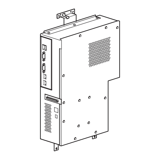
1. Image
controller
2. Power cord *1
3. Power cord *2
(for the wall
outlet)
4. Copier
LAN cable
(crossover
cable)
5. Image
transmission
cable
6. Ferrite Core
7. Other accesso-
ries *3
*1 This power cord is not used when installing the
image controller.
*2 This power cord cannot be used in Taiwan that
utilizes 110V power.
INSTALLATION MANUAL
Shape
Q'ty
1
A0YEIXC001DA
1
A00HIXC019HA
1
A00HIXE034HA
1
A00HIXC018HA
1
A0YEIXC003DA
1
A0YEIXC054DA
-
-
Video Interface Kit/Image Controller
*3 The accessories are not used when installing
the image controller.
Package contents of the video interface kit
VI-505
No.
Name
1. Relay circuit
board
2. Power cord *
(For connection
between copier
and IC)
3. Screw *
(4 × 8 mm)
4. Shoulder
screws for
mounting the
relay circuit
board
5. Shoulder
screws for the
relay circuit
board connec-
tor
6. Installation
manual
*
Using or not using the part depends on each
market.
After unpacking, be sure to get rid of the
packaging materials and keep them out of
the reach of children.
Putting the head in the plastic bag
involves danger of suffocation.
E-1
Shape
Q'ty
1
A0YEIXC004DA
1
A0YEIXC002DA
1
4040IXC046DA
2
A0YEIXC005DB
2
A0YEIXC047DA
1 set
4980IXC019DA
A0YE-9550-01
Advertisement

Related Manuals for Konica Minolta IC-412


Summary of Contents for Konica Minolta IC-412
- Page 1 VI-505/IC-412 Video Interface Kit/Image Controller INSTALLATION MANUAL Applied Machines: C652/C552/C452 COLOR MFP: 65 ppm/55 ppm/45 ppm Product Code: A0P0/A0P1/A0P2 I. Accessory parts *3 The accessories are not used when installing the image controller. Before starting to set up, check that the following are included.
-
Page 2: Installation Procedures
II. Part names <Port descriptions> Port 1 Ethernet 10Base-T/100Base-TX/1000Base-T network port (Port 1) Port 2 A00HIXC033HB Port 1 (For the LAN) Connect the network cable to the LAN. Port 2 (For the COPIER)* Use a crossover cable to connect to the LAN port of the copier. - Page 3 4. Remove the rear right cover (four screws). 7. Remove the two screws for the main circuit board. Note: The two screws removed here will be used to install the relay circuit board. A0YEIXC011DC 5. Remove the internal bracket (11 screws). A0YEIXC014DA 8.
- Page 4 10. While aligning the matchmarks on the relay cir- 13. Reinstall the internal bracket that has been cuit board and the main circuit board, connect removed in step 5 (11 screws). the connector coming from the back side of the 14.
- Page 5 19. Remove the two brackets from the copier (two 22. Insert the harness into the wire saddle. screws each). Wire saddle Note: The four screws removed here will be used to install the image controller. A0YEIXE052DA 23. Fix the end of the ground wire included in the power cord (for connection between copier and IC) to the copier (screw furnished with the video A0YEIXC044DA...
- Page 6 25. Connect the other end of the power cord to the 28. Reinstall the right side rear upper cover removed connector on the image controller. in step 2 (three screws). 29. Reinstall the right side rear lower cover removed Note: in step 17 (two screws).
- Page 7 21. Plug the supplied power cord (for the wall outlet) 24. Reinstall right side rear upper cover removed in into the power cord connector on the image con- step 2 (three screws). troller, and then secure the cord with the clamp. 25.
- Page 8 V. Connecting the copier and image con- b: Connecting the copier and image controller with the supplied copier LAN cable (cross- troller to a network over cable), and connecting the image con- The network functions of the copier can be used troller to a hub (LAN) even when the image controller is installed.
- Page 9 Note: 11. Specify settings for the following. • When manually specifying the IP address of the IP Address: Image controller IP address image controller Since the IP address of the copier is one num- Subnet Mask: Subnet mask for the con- ber higher than the IP address of the image nected network controller, consecutively numbered IP...
- Page 10 VII. Checking the setup with a test print After setting up the image controller, print the config- uration sheet to check that the controller is operating correctly. <To print a test page> 1. Press the [Utility/Counter] key on the copier. 2.
Need help?
Do you have a question about the IC-412 and is the answer not in the manual?
Questions and answers