
Related Manuals for Klein Tools CL330


Summary of Contents for Klein Tools CL330
- Page 1 CL330 ENGLISH INSTRUCTION MANUAL 400A AC Auto-Ranging Digital Clamp Meter True RMS Measurement Technology • OLED DISPLAY • AUTO-RANGING • DATA HOLD • RANGE HOLD • TEMPERATURE • BAR GRAPH 600V 400A Ω...
-
Page 2: General Specifications
ENGLISH GENERAL SPECIFICATIONS Klein Tools CL330 is an automatically ranging true root mean square (TRMS) digital clamp meter that measures AC current via the clamp, AC/DC voltage, resistance, continuity, frequency, capacitance, and tests diodes via test-leads, and temperature via a thermocouple probe. -
Page 3: Electrical Specifications
ELECTRICAL SPECIFICATIONS Function Range Resolution Accuracy 4.000V ±(1.5% + 5 digits) 40.00V 10mV AC Voltage ±(1.2% + 5 digits) (V AC) 400.0V 100mV 600V ±(1.5% + 5 digits) 400.0mV 0.1mV ±(1.0% + 8 digits) 4.000V DC Voltage 40.00V 10mV ±(0.8% + 3 digits) (V DC) 400.0V 100mV... - Page 4 ENGLISH ELECTRICAL SPECIFICATIONS Function Range Resolution Accuracy 40.00nF 0.010nF ±(4% + 25 digits) 400.0nF 0.100nF 4.000μF 0.001μF Capacitance ±(4% + 8 digits) 40.00μF 0.010μF 400.0μF 0.100μF 4.000mF 0.001mF ±(10% + 9 digits) Maximum Input: 600V AC RMS or 600V DC -40°...
-
Page 5: Symbols On Display
WARNINGS To ensure safe operation and service of the meter, follow these instructions. Failure to observe these warnings can result in severe injury or death. • Before each use verify meter operation by measuring a known voltage or current. • Never use the meter on a circuit with voltages that exceed the category based rating of this meter. -
Page 6: Feature Details
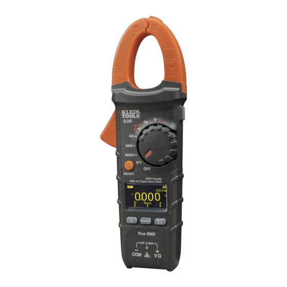
ENGLISH FEATURE DETAILS 4000 count OLED display "MAX/MIN" button Function selector switch Data Hold button Clamp Clamp trigger (press to open clamp) "COM" jack Arrow markings "VΩ" jack "SELECT" button Display brightness button Hand & finger guard "RANGE" button... -
Page 7: Display Brightness
FUNCTION BUTTONS ON/OFF To power ON the meter, rotate the Function Selector switch from the OFF setting to any measurement setting. To power OFF the meter, rotate the Function Selector switch to the OFF setting. By default, the meter will automatically power OFF after 10 minutes of inactivity. If the meter automatically powers-OFF while in a measurement setting, press any button ( ) to power ON the... - Page 8 ENGLISH FUNCTION BUTTONS RANGE The meter defaults to auto-ranging mode Auto. This mode automatically determines the most appropriate measurement range for the testing that is being conducted. To manually force the meter to measure in a different range, use the "RANGE" button 1.
- Page 9 OPERATING INSTRUCTIONS CONNECTING TEST LEADS Do not test if leads are improperly seated. Results could cause intermittent display readings. To ensure proper connection, firmly press leads into the input jack completely. INCORRECT CORRECT TESTING IN CAT III / CAT IV MEASUREMENT LOCATIONS Ensure the test lead shield is pressed firmly in place.
- Page 10 ENGLISH OPERATING INSTRUCTIONS AC CURRENT (LESS THAN 400A) AC Current is measured by pressing the clamp trigger to open the clamp and placing it around a current-carrying wire. When measuring, care should be taken to ensure that the clamp is completely closed with trigger fully released, and that the wire passes perpendicularly through the center of the clamp in line with...
- Page 11 OPERATING INSTRUCTIONS AC/DC VOLTAGE (LESS THAN 600V) 1. Insert RED test lead into VΩ jack , and BLACK test lead into COM jack , and rotate function selector switch to the setting for AC or DC measurements. The meter defaults to AC measurement.
- Page 12 ENGLISH OPERATING INSTRUCTIONS CONTINUITY 1. Insert RED test lead into VΩ jack , and BLACK test lead into COM jack , and rotate function selector switch to the Continuity/Resistance/Capacitance/Diode-Test setting. NOTE: The meter defaults to Continuity testing in this mode. Ensure that the Continuity Testing icon is visible on the display.
-
Page 13: Resistance Measurements
OPERATING INSTRUCTIONS RESISTANCE MEASUREMENTS 1. Insert RED test lead into VΩ jack , and BLACK test lead into COM jack , and rotate function selector switch to the Continuity/Resistance/Capacitance/Diode-Test setting. NOTE: The meter defaults to Continuity testing in this mode. Press the "SELECT"... - Page 14 ENGLISH OPERATING INSTRUCTIONS CAPACITANCE 1. Insert RED test lead into VΩ jack , and BLACK test lead into COM jack , and rotate function selector switch to the Continuity/Resistance/Capacitance/Diode-Test setting. NOTE: The meter defaults to Continuity testing in this mode. Press the "SELECT"...
-
Page 15: Diode Test
OPERATING INSTRUCTIONS DIODE TEST 1. Insert RED test lead into VΩ jack , and BLACK test lead into COM jack , and rotate function selector switch to the Continuity/Resistance/Capacitance/Diode-Test setting. NOTE: The meter defaults to Continuity testing in this mode. Press the "SELECT"... -
Page 16: Bar Graph
ENGLISH OPERATING INSTRUCTIONS BAR GRAPH 1. The Bar Graph emulates an analog representation of the measurement. In any given range the bar graph scales from zero on the left hand side to the maximum value of the range on the right hand side of the display. -
Page 17: Maintenance
MAINTENANCE BATTERY REPLACEMENT When the Battery Strength Indicator shows low battery strength( batteries must be replaced. 1. Remove screw from battery door. 2. Replace 3 x AAA batteries (note proper polarity). 3. Replace battery door and fasten securely with screw. To avoid risk of electric shock, disconnect leads from any voltage source before removing battery door. - Page 18 ENGLISH CLEANING Be sure meter is turned off and wipe with a clean, dry lint-free cloth. Do not use abrasive cleaners or solvents. STORAGE For everyday storage turn meter off, disconnect test-leads, and store in the carry case provided for the meter. NOTE: Storing the meter for any period of time in the carrying case with the test-leads inserted is not recommended.
Need help?
Do you have a question about the CL330 and is the answer not in the manual?
Questions and answers