Klein Tools CL390 Instruction Manual
400a ac/dc auto-ranging digital clamp meter
Hide thumbs
Also See for CL390:
- Instruction manual (57 pages) ,
- Instruction manual (28 pages) ,
- User manual
Table of Contents
Advertisement
1.800.544.2843
ENGLISH
INSTRUCTION MANUAL
400A AC/DC Auto-Ranging
400A AC/DC Auto-Ranging
Digital Clamp Meter
Digital Clamp Meter
Digital Clamp Meter
True RMS
True RMS
True RMS
Measurement
Measurement
Measurement
Technology
-40° –
1832°F
-40° –
1000°C
• AC/DC CURRENT
AC/DC CURRENT
• HIGH VISIBILITY
HIGH VISIBILITY
DISPLAY
• NON-CONTACT
VOLTAGE TESTING
VOLTAGE TESTING
VOLTAGE TESTING
• DC MICRO-AMPS
DC MICRO-AMPS
• AUTO-RANGING
AUTO-RANGING
• DATA & RANGE HOLD
DATA & RANGE HOLD
DATA & RANGE HOLD
• TEMPERATURE
600V
400A
40M
2 m
www.calcert.com
15
10
20
5
25
0
30
CL390
5001748
CAT III
600V
sales@calcert.com
Advertisement
Table of Contents

Related Manuals for Klein Tools CL390


Summary of Contents for Klein Tools CL390
- Page 1 CL390 ENGLISH INSTRUCTION MANUAL 400A AC/DC Auto-Ranging 400A AC/DC Auto-Ranging Digital Clamp Meter Digital Clamp Meter Digital Clamp Meter True RMS True RMS True RMS Measurement Measurement Measurement Technology -40° – 1832°F -40° – 1000°C • AC/DC CURRENT AC/DC CURRENT •...
-
Page 2: General Specifications
ENGLISH GENERAL SPECIFICATIONS Klein Tools CL390 is an automatically ranging true root mean square (TRMS) digital clamp meter that measures AC/DC current via the clamp, AC/DC voltage, DC microamps, resistance, continuity, frequency, capacitance, tests diodes via test-leads, and temperature via a thermocouple probe. It features a high visibility, reverse contrast LCD display that optimizes viewability both in dark or bright ambient lighting. -
Page 3: Electrical Specifications
ELECTRICAL SPECIFICATIONS Function Range Resolution Accuracy 400.0mV 0.1mV ±(1.8% + 5 digits) 4.000V 0.001V ±(1.5% + 5 digits) AC Voltage 40.00V 0.01V (V AC) ±(1.2% + 5 digits) 400.0V 0.1V 600V ±(1.5% + 5 digits) 400.0mV 0.1mV ±(1.0% + 8 digits) 4.000V 0.001V DC Voltage... - Page 4 ENGLISH ELECTRICAL SPECIFICATIONS Function Range Resolution Accuracy 40.00nF 0.01nF ±(4% + 25 digits) 400.0nF 0.1nF 4.000 F 0.001 F Capacitance ±(4% + 8 digits) 40.00 F 0.01 F 400.0 F 0.1 F 4.000mF 0.001mF ±(5% + 9 digits) Maximum Input: 600V AC RMS or 600V DC -40°...
-
Page 5: Symbols On Lcd
WARNINGS • Never use the meter on a circuit with voltages that exceed the category based rating of this meter. • Do not use the meter during electrical storms or in wet weather. • Do not use the meter or test leads if they appear to be damaged. •... -
Page 6: Feature Details
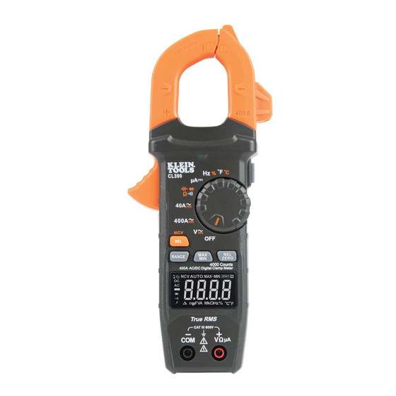
ENGLISH FEATURE DETAILS NOTE: There are no user-serviceable parts inside meter. 4000 count LCD display "REL/ZERO" button Function selector switch HOLD/Brightness button Clamp Clamp trigger "COM" jack Arrow markings "V µA" jack "SEL/NCV" button "RANGE" button NCV Light "MAX/MIN" button NCV Sensing Antenna 1.800.544.2843 www.calcert.com... -
Page 7: Backlight Brightness
FUNCTION BUTTONS ON/OFF To power ON the meter, rotate the Function Selector switch from the OFF setting to any measurement setting. To power OFF the meter, rotate the Function Selector switch to the OFF setting. The Auto- Power Off icon will be visible in the display. -
Page 8: Relative Mode
ENGLISH FUNCTION BUTTONS MAX/MIN The "MAX/MIN" function can be used when measuring with voltage, current, resistance, temperature, and DC A functions. When the "MAX/MIN" button is pressed, the meter keeps track of the Maximum and Minimum values, and the difference between the Maximum and Minimum values while continuing to take samples. - Page 9 OPERATING INSTRUCTIONS CONNECTING TEST LEADS Do not test if leads are improperly seated. Results could cause intermittent display readings. To ensure proper connection, firmly press leads into the input jack completely. INCORRECT CORRECT TESTING IN CAT III MEASUREMENT LOCATIONS Ensure the test lead shield is pressed firmly in place. Failure to use the CATIII / CATIV shield increases arc-flash risk.
- Page 10 ENGLISH OPERATING INSTRUCTIONS AC/DC CURRENT (LESS THAN 400A) AC Current is measured by pressing the clamp trigger to open the clamp and placing it around a current-carrying wire. When measuring, care should be taken to ensure that the clamp is completely closed with trigger fully released, and that the wire passes perpendicularly through the center of the clamp in line with the arrow markings...
- Page 11 OPERATING INSTRUCTIONS AC/DC VOLTAGE (LESS THAN 600V) 1. Insert RED test lead into V µA jack , and BLACK test lead into COM jack , and rotate function selector switch to the setting for AC or DC measurements. The meter defaults to AC measurement.
- Page 12 ENGLISH OPERATING INSTRUCTIONS CONTINUITY 1. Insert RED test lead into V µA jack , and BLACK test lead into COM jack , and rotate function selector switch to the Continuity/Resistance/Capacitance/Diode-Test setting. NOTE: The meter defaults to Continuity testing in this mode. Ensure that the Continuity Testing icon is visible on the display.
-
Page 13: Resistance Measurements
OPERATING INSTRUCTIONS RESISTANCE MEASUREMENTS 1. Insert RED test lead into V µA jack , and BLACK test lead into COM jack , and rotate function selector switch to the Continuity/Resistance/Capacitance/Diode-Test setting. NOTE: The meter defaults to Continuity testing in this mode. Press the "SEL/NCV"... - Page 14 ENGLISH OPERATING INSTRUCTIONS CAPACITANCE 1. Insert RED test lead into V µA jack , and BLACK test lead into COM jack , and rotate function selector switch to the Continuity/Resistance/Capacitance/Diode-Test setting. NOTE: The meter defaults to Continuity testing in this mode. To measure capacitance, press the "SEL/NCV"...
-
Page 15: Diode Test
OPERATING INSTRUCTIONS DIODE TEST 1. Insert RED test lead into V µA jack , and BLACK test lead into COM jack , and rotate function selector switch to the Continuity/Resistance/Capacitance/Diode-Test setting. NOTE: The meter defaults to Continuity testing in this mode. Press the "SEL/NCV"... -
Page 16: Frequency / Duty-Cycle
ENGLISH OPERATING INSTRUCTIONS FREQUENCY / DUTY-CYCLE 1. Insert RED test lead into V µA jack and BLACK test lead into COM jack , and rotate function selector switch to the Frequency/Duty-Cycle setting. NOTE: The meter defaults to Frequency testing in this mode. To enter Duty-Cycle testing mode, press the "SEL/NCV"... -
Page 17: Maintenance
MAINTENANCE BATTERY REPLACEMENT When indicator is displayed on LCD, batteries must be replaced. 1. Loosen captive screw and remove battery cover. 2. Replace 3 x AAA batteries (note proper polarity). 3. Replace battery cover and fasten screw securely. Replace battery cover and fasten screw securely. To avoid risk of electric shock, disconnect leads from any voltage source before removing battery door.
Need help?
Do you have a question about the CL390 and is the answer not in the manual?
Questions and answers