
Subscribe to Our Youtube Channel
Related Manuals for Waters 515 HPLC


Summary of Contents for Waters 515 HPLC
- Page 1 515 HPLC Pump Operator’s Guide WAT068980/Revision 5 Copyright © Waters Corporation 2016 All rights reserved...
-
Page 2: Copyright Notice
Corporation assumes no responsibility for any errors that may appear in this document. This document is believed to be complete and accurate at the time of publication. In no event shall Waters Corporation be liable for incidental or consequential damages in connection with, or arising from, its use. -
Page 3: Customer Comments
Contacting Waters ® Contact Waters with enhancement requests or technical questions regarding the use, transportation, removal, or disposal of any Waters product. You can reach us via the Internet, telephone, or conventional mail. Waters contact information Contacting medium Information... -
Page 4: Safety Considerations
Safety considerations Some reagents and samples used with Waters instruments and devices can pose chemical, biological, and radiological hazards. You must know the potentially hazardous effects of all substances you work with. Always follow Good Laboratory Practice, and consult your organization’s safety representative for guidance. -
Page 5: Operating This Instrument
This guide is intended for personnel who install, operate, and maintain the Waters 515 HPLC Pump. Intended use of the Waters 515 HPLC Pump The Waters 515 HPLC Pump is for research use only. Calibrating To calibrate LC systems, follow acceptable calibration methods using at least... -
Page 6: Quality-Control
standards should include the entire range of QC samples, typical specimens, and atypical specimens. When calibrating mass spectrometers, consult the calibration section of the operator’s guide for the instrument you are calibrating. In cases where an overview and maintenance guide, not operator’s guide, accompanies the instrument, consult the instrument’s online Help system for calibration instructions. -
Page 7: Ec Authorized Representative
EC authorized representative Waters Corporation Stamford Avenue Altrincham Road Wilmslow SK9 4AX UK Telephone: +44-161-946-2400 Fax: +44-161-946-2480 Contact: Quality manager... - Page 8 viii...
-
Page 9: Table Of Contents
Safety advisories ....................iv Operating this instrument .................. v Applicable symbols ....................v Audience and purpose..................v Intended use of the Waters 515 HPLC Pump ............ v Calibrating ......................v Quality-control ....................vi ISM classification ....................vi ISM Classification: ISM Group 1 Class B ............vi EC authorized representative ................ - Page 10 2 Installing the Waters 515 Pump ............2-1 Site requirements ..................... 2-2 Unpacking ......................2-3 Making electrical connections ............... 2-4 Replacing the power supply fuses ..............2-4 Connecting the power supply ................2-5 Connecting for remote operation..............2-6 Making fluidic connections ................2-6 Connecting the eluent supply................
- Page 11 Powering off the pump .................. 3-26 4 Maintaining and Troubleshooting the Waters 515 Pump ..... 4-1 Maintenance considerations ................4-2 Safety and handling..................4-2 Proper operating procedures ................4-2 Spare parts ....................... 4-2 Contacting Waters technical service............... 4-2 Diagnostic tests ....................4-3 Retention time stability monitoring ...............
- Page 12 Warning symbols ....................A-2 Task-specific hazard warnings................ A-2 Specific warnings ..................... A-3 Caution symbol ....................A-5 Warnings that apply to all Waters instruments ......... A-6 Electrical and handling symbols ..............A-12 Electrical symbols ..................A-12 Handling symbols ..................A-13 B Specifications ..................B-1 C Accessories and Spare Parts ..............
- Page 13 Waters 515 Pump Overview Contents Topic Page Overview Fluid-handling components Electronics components Operating modes...
-
Page 14: Waters 515 Pump Overview
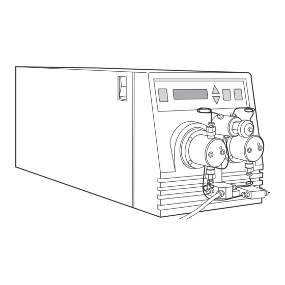
A keypad and LCD display lets you quickly enter parameters for the run. In addition, the display provides a readout of status, diagnostic, and monitoring information for the pump. The figure below shows a Waters 515 HPLC Pump. Waters 515 HPLC Pump... -
Page 15: Fluid-Handling Components
Fluid-handling components Before you install the Waters 515 pump, familiarize yourself with its components. The figure below identifies the fluid-handling components of the Waters 515 pump and the table titled “Fluid-handling components” on page 1-3 describes their functions. Pump fluid-handling components... -
Page 16: Electronics Components
Electronics components Before you install the 515 pump, familiarize yourself with its electronics components as illustrated in the figure below. The table titled “Electronics components” on page 1-5 describes the functions of the electronics components. Waters 515 Pump Overview... - Page 17 Pump electronics components Front and side views Power switch Keypad and LCD display TP01407 Rear view Cooling fan vent External controller Power entry module connector TP01409 Electronics components Component Function Cooling fan vent Exhausts air for cooling internal electronics. External controller Provides connection for the pump control cable, connector which connects the pump to an external control...
-
Page 18: Operating Modes
Power switch Used to power the pump on and off. Operating modes The 515 HPLC Pump can operate in two control modes: • Stand-alone mode • Remote control mode (under the control of a data system or external... - Page 19 For example, the figure below illustrates a three-pump configuration under the control of a Millennium Chromatography Manager workstation. Three-pump configuration under Millennium Chromatography Manager control (using the PCM) IEEE-488 cable IEEE-488 connector Millennium Chromatography Manager Pump Control Module (PCM) Pump control cables Pump Pump...
- Page 20 Waters 515 Pump Overview...
-
Page 21: Installing The Waters 515 Pump
Installing the Waters 515 Pump This chapter provides a list of site requirements for your Waters 515 HPLC Pump, and describes how to unpack and install the pump. Contents Topic Page Site requirements Unpacking Making electrical connections Making fluidic connections... -
Page 22: Site Requirements
Site requirements Install the 515 HPLC Pump at a site that meets the specifications indicated in the table below. Installation site requirements Factor Requirement Temperature 4 to 40 °C (39 to 104 °F) Relative humidity 20 to 80%, noncondensing Bench space Width: 7.5 in. -
Page 23: Unpacking
8.0 in (20.3 cm) 18.5 in (47 cm) 7.5 in (19.1 cm) TP0 1 4 1 0 Unpacking The Waters 515 HPLC Pump is shipped in one carton that contains the following items: • Waters 515 Pump • Startup Kit •... -
Page 24: Making Electrical Connections
Inspect all items for damage. Immediately report any shipping damage to both the shipping company and your Waters representative. Contact Waters Technical Service at 800 252-4752, Canadian and U.S. customers only. Other customers, call your local Waters subsidiary or call Waters corporate headquarters for assistance in Milford, Massachusetts (U.S.A.). -
Page 25: Connecting The Power Supply
Install the fuse holder in its receptacle. Connecting the power supply The 515 HPLC Pump automatically adjusts for AC input voltage in the range from 85 to 264 VAC at 47 to 63 Hz. To connect the power supply: Insert the 115 V or 230 V power cord into the power connector on the rear of the pump. -
Page 26: Connecting For Remote Operation
If necessary, see the Waters Pump Control Module Operator’s Manual or the Waters Model 680 Automated Gradient Controller Operator’s Manual for more information. Making fluidic connections This section describes how to make fluidic connections to the Waters 515 pump. The steps include: • Connecting the eluent supply •... - Page 27 • Reservoir containing filtered, degassed eluent • Stainless steel solvent filter (Startup Kit) • Plastic tubing cutter (part number WAT031795) • Razor blade Connecting eluent tubing to the pump inlet To connect the eluent tubing to the pump inlet: Measure the length of 1/8-inch PTFE tubing required to connect the reservoir to the inlet manifold on the pump.
-
Page 28: Connecting The Pump Outlet
Follow the instructions in this section to connect the pump outlet to the next instrument in the flow path. If you are configuring multiple pumps for high-pressure gradient delivery, also see “Connecting for high-pressure gradient operation” on page 2-11. Installing the Waters 515 Pump... - Page 29 Connecting the pump outlet involves: • Cutting the tubing • Attaching a compression fitting to each end of the tubing • Connecting each end of the tubing Required materials • Two stainless ferrules and standard compression screws (Startup Kit) • 1/16-inch OD stainless tubing (Startup Kit) •...
- Page 30 To connect the stainless tubing assembly: While pressing one end of the tubing assembly into the pump outlet fitting, finger-tighten the compression screw, then use the 5/16-inch wrench to tighten the screw another 1/8-turn. 2-10 Installing the Waters 515 Pump...
-
Page 31: Connecting For High-Pressure Gradient Operation
Connecting the outlet tube Tip: Leave the instrument end of the outlet tubing disconnected until you have primed the pump and flushed the system as described in “Preparing the 515 pump” on page 3-13. After you prime the pump and purge the system, press the free end of the tubing assembly into the injector or next device in your HPLC system and finger-tighten the compression screw. - Page 32 Waters EDIT MENU ENTER STOP 515 HPLC Pump Tee (part number WAT075215) Waters EDIT MENU ENTER STOP 515 HPLC Pump Tee (part number WAT075215) To injector Optional static mixer (part number WAT051518) 2-12 Installing the Waters 515 Pump...
-
Page 33: Using The Waters 515 Pump
Using the Waters 515 Pump This chapter describes how to prepare and operate the Waters 515 HPLC Pump. Where appropriate, instructions are provided for both stand-alone and remote operation. Contents Topic Page Powering on the pump Keypad and display overview... -
Page 34: Powering On The Pump
Powering on the pump Tip: If your 515 pump is connected to a Waters 680 Automated Gradient Controller, and you power on the controller with the pump running in the Remote mode, you may hear the pump operate briefly. This is due to a spurious signal from the controller when it is powered on. -
Page 35: Diagnostics Failure
The LCD display indicates an EEPROM check failure and prompts you to press the Menu key. Pressing the Menu key acknowledges the failure and sets all parameters to their factory defaults. “Maintaining and Troubleshooting the Waters 515 Pump”, for more information about dealing with EEPROM diagnostics failures. -
Page 36: Keypad
The LCD display provides prompts for when to use the Edit/Enter key while editing in the Calibrate menu. See the table titled “515 pump operating parameters” on page 3-7 for more information about the Calibrate menu. Using the Waters 515 Pump... -
Page 37: Lcd Display
Keypad functions (Continued) Function Scrolls to the next menu item. If you are editing a menu item (indicated by a MENU blinking cursor), pressing this key stores the current parameter and moves to the next parameter (when you edit the Flow parameter, you need to press Menu twice to move to the next parameter). - Page 38 (first parameter to appear when pump is powered on) Purge (high-pressure limit) (low-pressure limit) Mode (local or remote) Comp (compressibility factor) Calibrate 0 Pressure Head Size Flow Rate Calibration Strokes on Unit Strokes on Seals Unit Using the Waters 515 Pump...
- Page 39 515 pump operating parameters Parameter Function Details Flow Selects flow rate The flow rate range is 0.000 to 10.000 for local mL/min. The default setting is 1.000 (stand-alone) mL/min. With the optional 225-µL head, operation the flow rate range is 0.000 to 22.500 mL/min.
- Page 40 Unit selected (see the Unit parameter section in this table). Refer to the Mode parameter section in this table for information about Local and Rem mode. Using the Waters 515 Pump...
- Page 41 515 pump operating parameters (Continued) Parameter Function Details Selects the In Local mode: Pressure less than or low-pressure limit equal to the LPL for 90 sec stops the pump. In Rem mode: Pressure less than or equal to the LPL for 90 sec causes the pump to send a pressure-limit output signal to the external controller.
- Page 42 Strokes on Displays the total The value is the total number of plunger Unit number of plunger strokes. This value is for reference only strokes for the and cannot be reset. pump 3-10 Using the Waters 515 Pump...
- Page 43 515 pump operating parameters (Continued) Parameter Function Details Strokes on Displays the The value shown is the total number of Seals accumulated plunger strokes accumulated since the number of plunger parameter was last reset.“Resetting strokes for the strokes on seals” on page 4-8 for details.
-
Page 44: Editing Or Entering Parameters In Local Or Remote Modes
Editing or entering parameters in local or remote modes Press the Up, Down, or Menu key to display the appropriate parameter in the menu items area. Press the Edit/Enter key to position the blinking cursor within the parameter. 3-12 Using the Waters 515 Pump... -
Page 45: Preparing The 515 Pump
Tip: When you need to edit a digit in the Flow parameter setting, press the Edit/Enter key until the cursor is positioned over the digit you want to change. You cannot move the cursor directly to the left; if you need to edit a digit to the left of the blinking cursor, simply continue to press Edit/Enter until the cursor wraps to the appropriate digit. - Page 46 To prevent air from being drawn into the pump, keep the eluent level in the reservoir at least 4 inches (10 cm) higher than the inlet manifold. Do not place eluent reservoirs on top of the Waters 515 pump. •...
-
Page 47: Priming The Pump
Priming the pump Priming is necessary to ensure proper pump operation when: • You start the pump for the first time. • You change eluent. • The system has been idle for some time. Before priming • Locate the priming syringe from the Startup Kit. •... - Page 48 Press the Run/Stop key to stop the pump. Caution: To prevent eluent flow through the pump heads under gravity pressure, never leave the pump unattended with the draw-off valve in the open position. 3-16 Using the Waters 515 Pump...
-
Page 49: Purging The System
Purging the system Purging ensures that all eluent in the fluidic path is replaced with new eluent before you run samples. Purge the system when: • You start the pump for the first time. • You change eluent or add fresh eluent. •... -
Page 50: Equilibrating The System
Use the Up or Down key to increase or decrease the value of the digit. If necessary, repeat steps a and b for the other digits until the 3-18 Using the Waters 515 Pump... - Page 51 Equilibrating for remote operation Caution: If your 515 pump is connected to a Waters 680 Automated Gradient Controller, do not power off the controller if the pump is running. Doing so may damage the column due to a spurious pressure output signal from the controller when it is powered off.
- Page 52 Monitor Baseline control button and an instrument method to handle equilibration. See the Millennium documentation. • If the pump is connected to a Waters ExpertEase system through a PCM, use the Monitor Baseline selection and a specified method to handle equilibration. See the ExpertEase documentation. •...
-
Page 53: Operating The Pump
Operating the pump This section describes how to operate the 515 pump in either a stand-alone or remote configuration. Stand-alone pump operation Follow the steps in this procedure if your HPLC system is set up in an isocratic configuration where you manually control the operation of the 515 pump from the pump keypad. -
Page 54: Remote Pump Operation
Before you operate the pump in a remote configuration, make sure: • You have already completed any required priming, purging, and equilibrating as described in “Preparing the 515 pump” on page 3-13. • Eluent reservoirs are filled with filtered, degassed eluent. 3-22 Using the Waters 515 Pump... - Page 55 • If your pump is connected to a Waters 680 Automated Gradient Controller, the controller is powered on before you power on the pump. Warning: To avoid chemical hazards, observe safe laboratory practices when you handle eluents. See the Material Safety Data Sheets for the eluents you use.
-
Page 56: Changing Parameters During A Run
Stop the pump at any time, press the Run/Stop key. Tip: If your 515 pump is connected to a Waters 680 Automated Gradient Controller, and you power on the controller with the 515 pump running in the Remote mode, you may hear the pump operate briefly. This is due to a spurious signal from the controller when it is powered on. -
Page 57: Required Materials
Required materials • 10-mL volumetric flask • Stopwatch • Degassed reservoir of selected eluent Procedure To adjust for compressibility: Disconnect the 515 pump outlet from the column to eliminate all system backpressure. Select the flow rate specified by your separations method, then simultaneously press the Run/Stop key and start the stopwatch. -
Page 58: Powering Off The Pump
If the pump is running, press the Run/Stop key. Tip: If your 515 pump is connected to a Waters 680 Automated Gradient Controller, and you power on the controller with the 515 pump running in the Remote mode, you may hear the pump operate briefly. This is due to a spurious signal from the controller when it is powered on. -
Page 59: Maintaining And Troubleshooting The Waters 515 Pump
Maintaining and Troubleshooting the Waters 515 Pump This chapter provides important safety and handling considerations for the 515 pump, describes how to run various diagnostics and set pump calibration parameters, describes how to clean and replace pump components, and explains how to diagnose and resolve pump problems. -
Page 60: Maintenance Considerations
Warning: • To prevent injury, always observe good laboratory practices when you handle eluents, change tubing, or operate the 515 HPLC Pump. Know the physical and chemical properties of the eluents. See the Material Safety Data Sheets for the eluents in use. -
Page 61: Diagnostic Tests
Diagnostic tests Regular diagnostic tests can help you to track system performance and prevent or identify potential problems before they interfere with operation. Common tests include: • Retention time stability tests • Ramp-and-decay test Retention time stability monitoring Observing retention time stability during system suitability tests is useful for determining the performance of your HPLC system and its components, including the pump. - Page 62 12. Repeat steps 5 through 11 to test the left pump head. Maintaining and Troubleshooting the Waters 515 Pump...
-
Page 63: Calibrating The Pump
13. If the pressure decay for either pump head is greater than 0.15, you may have dirty check valves (see “Cleaning and replacing check valves” on page 4-18). Remove and clean the inlet and outlet check valves. If the pump problem persists, replace the check valves. 14. -
Page 64: Setting The Head Size
Tip: If the pressure reading is greater than 100 psi (689.5 kPa or 6.68 bars), or less than –100 psi (–689.5 kPa or –6.68 bars), contact Waters Technical Service. Press Edit/Enter. When prompted, press Edit/Enter again to set the 0 Pressure parameter. -
Page 65: Calibrating The Flow Rate
Press Edit/Enter to access the Head Size submenu. Press the Up or Down key to change the Head size parameter to the correct value. Press Menu to store the parameter. Press Menu until you are prompted to exit. Press Edit/Enter to exit the Calibrate menu. Check the HPL and LPL parameter settings, and adjust them if necessary for the new head size. -
Page 66: Resetting Strokes On Seals
12. Press Edit/Enter to exit the Calibrate menu. Resetting strokes on seals The following procedure describes how to reset the Strokes on Seals parameter. This parameter records the number of accumulated strokes for the Maintaining and Troubleshooting the Waters 515 Pump... -
Page 67: Cleaning And Replacing Seals And Plungers
Press Edit/Enter to exit the Calibrate menu. Cleaning and replacing seals and plungers The plungers in the Waters 515 pump are ultra-smooth, chemically inert sapphire rods. Salt crystals that precipitate out from the eluent can form on the plunger and cause wear on the plunger seals and on the plunger itself. The result is a slow leak and a very slight cyclic pressure fluctuation, with a possible increase in retention time. - Page 68 When the indicator rod fully retracts into the pump head, press Run/Stop again to turn off the pump. This ensures that the weight of the pump head does not rest on the plunger while you remove the head. 4-10 Maintaining and Troubleshooting the Waters 515 Pump...
- Page 69 Use the 5/16-inch open-end wrench to remove the inlet and outlet tubing from the check valves on the pump. Use the 5/32-inch Allen wrench to remove the two pump head assembly mounting bolts. Loosen the bolts 1/2-turn at a time for the first two turns.
- Page 70 Set the Flow parameter to 0.3 mL/min, then press Run/Stop to start the pump. Verify that the indicator rod moves freely. Press Run/Stop to stop the pump. 4-12 Maintaining and Troubleshooting the Waters 515 Pump...
-
Page 71: Cleaning And Replacing The Plungers
Reset the Strokes on Seals parameter as described in “Resetting strokes on seals” on page 4-8. 10. Perform the following steps: Reconnect the inlet and outlet tubing to the pump head. Reconnect the eluent line to the pump inlet manifold. Remove the fitting plug from the pump outlet, then reposition the eluent reservoir. - Page 72 When the plunger is fully extended, press Run/Stop again to stop the pump. Use the snap-ring pliers to remove the snap-ring that holds the plunger in place. Remove the plunger assembly and set it aside. 4-14 Maintaining and Troubleshooting the Waters 515 Pump...
- Page 73 Removing the plunger assembly Cleaning the plunger Warning: To avoid the possibility of eye injury or cuts, handle the plunger with care. Wear safety glasses and use the plunger insertion tool. Be aware that the pieces of a broken plunger are very sharp. Clean the plunger by sonicating the plunger in 50:50 methanol/water for a few minutes.
- Page 74 You may find this step easier if you set the pump on its back. Caution: Be careful not to damage the external controller connector if you set the pump on its back. 4-16 Maintaining and Troubleshooting the Waters 515 Pump...
- Page 75 Inserting the plunger Plunger Snap-ring insertion pliers tool Press Run/Stop to start the pump. When the plunger is fully retracted, press Run/Stop again to stop the pump. With the indicator rod hole oriented to the upper right, reinstall the head support assembly. Alternately tighten the four screws. Do not overtighten.
-
Page 76: Cleaning And Replacing Check Valves
Cleaning and replacing the inlet check valve Required materials • 5/16-inch open-end wrench (Startup Kit) • 1/2-inch open-end wrench (Startup Kit) • Priming syringe (Startup Kit) • Fitting plug (Startup Kit) • Replacement check valve • Methanol 4-18 Maintaining and Troubleshooting the Waters 515 Pump... - Page 77 Replacing the inlet check valve To replace the inlet check valve: Purge the pump with methanol as described in “Purging the system” on page 3-17. If methanol is not miscible with your current eluent, use an intermediate eluent. Caution: Before you continue with this procedure, lower the eluent reservoir to eliminate gravity flow of eluent.
- Page 78 Tighten the check valve another 1/2-turn with the 1/2-inch wrench. 11. Reinstall the pump head as described in “Replacing the plunger seals” on page 4-9. 4-20 Maintaining and Troubleshooting the Waters 515 Pump...
-
Page 79: Replacing The Outlet Check Valve
12. Reconnect the inlet and outlet tubing to the pump head. While tightening the compression screw, hold the housing to prevent it from turning. 13. Reconnect the eluent supply line to the inlet manifold on the pump. 14. Remove the fitting plug from the pump outlet, then reposition the eluent reservoir. - Page 80 Hold the pump head upside-down in one hand with the outlet check valve housing facing the floor, then remove the housing (see the figure “Removing the outlet check valve” on page 4-23). 4-22 Maintaining and Troubleshooting the Waters 515 Pump...
- Page 81 10. Remove the cartridge from the housing and replace it with the new cartridge. Removing the outlet check valve Caution: The arrow printed on the check valve cartridge indicates the direction in which it will allow liquid to flow. Therefore, its direction is critical for proper operation.
-
Page 82: Replacing The Draw-Off Valve
1/2-turn to open the valve. Use the syringe to withdraw all the methanol. Use the 5/16-inch open-end wrench to disconnect the three stainless compression screws from the draw-off valve. 4-24 Maintaining and Troubleshooting the Waters 515 Pump... -
Page 83: Installing The Draw-Off Valve
Draw-off valve/inlet manifold assembly Compression screw Handle Draw-off valve Allen screw (7/64-Inch) Cutout in bracket Bracket Eluent line Inlet manifold TP01416 Use the 5/16-inch open-end wrench to disconnect the two stainless compression screws from the inlet manifold (these screws connect the inlet manifold to the inlet check valves). -
Page 84: Troubleshooting
If you encounter problems troubleshooting the 515 Pump that you cannot resolve, contact Waters Technical Service at 800 252-4752, Canadian and U.S. customers only. Other customers, call your local Waters subsidiary or call Waters corporate headquarters for assistance in Milford, Massachusetts (U.S.A.). -
Page 85: Troubleshooting Error Messages And Pump Malfunctions
Check eluent viscosity (the observed pressure may be normal for the column/eluent blend). If necessary, change to less viscous eluent. Defective pressure Contact Waters Technical transducer Service. Blocked outlet tubing or Locate source of blockage. Clean fluid path (in pump... - Page 86 Blown fuse Replace the fuses (see“Replacing the power supply fuses” on page 2-4). LCD display is EEPROM failure Contact Waters Technical blank, but fan is Service. running 4-28 Maintaining and Troubleshooting the Waters 515 Pump...
- Page 87 With Flow parameter set to zero of adjustment or and with no system backpressure, defective set the Zero Pressure parameter. If problem continues, contact Waters Technical Service. Pump not primed Prime the pump (see “Priming the pump” on page 3-15).
- Page 88 Prime pump (see “Priming the head pump” on page 3-15). Tubing ID too small Use correct tubing. Ruptured high-pressure Contact Waters Technical noise filter (indicated by Service. leak at bottom of front bezel) 4-30 Maintaining and Troubleshooting the Waters 515 Pump...
- Page 89 Troubleshooting error messages and pump malfunctions (Continued) Symptom Possible cause Corrective action Pump not Defective pump motor Contact Waters Technical delivering eluent Service. (continued) Defective circuit board Contact Waters Technical Service. Leak from pump Worn pump plunger Replace defective plunger seals...
- Page 90 Pressure transducer out Set Flow parameter to zero and of adjustment or adjust the zero pressure. If defective problem continues, contact Waters Technical Service. 4-32 Maintaining and Troubleshooting the Waters 515 Pump...
-
Page 91: Identifying And Correcting Noises
Identifying and correcting noises The table below is a guide to troubleshooting and correcting noises in the Waters 515 pump. Identifying Noises Symptom Possible cause Corrective action Click or loud snap Binding plunger seal If click does not stop and... -
Page 92: Identifying Chromatographic Problems
Use correct eluent. Column contaminated Clean/replace column. Incorrect column Use correct column. Air bubble in pump Degas all eluents, prime pump head (see“Priming the pump” on page 3-15). Clogged eluent filter Replace filter. 4-34 Maintaining and Troubleshooting the Waters 515 Pump... - Page 93 Identifying chromatographic problems (Continued) Symptom Possible cause Corrective action Reduced retention Incorrect flow rate Change flow rate. times Incorrect eluent Change composition. composition High column Reduce column temperature. temperature Incorrect eluent Use correct eluent. Column contaminated Clean/replace column. Incorrect column Use correct column.
- Page 94 Radio frequency noise Eliminate interference. (short- or long-term cycling) Baseline noise Ambient temperature Stabilize ambient cycling, fluctuations temperature. long-term Integrator or recorder Check integrator or recorder (approximately faulty for excessive baseline noise. 1 hour) 4-36 Maintaining and Troubleshooting the Waters 515 Pump...
- Page 95 Identifying chromatographic problems (Continued) Symptom Possible cause Corrective action Baseline noise, Eluents not properly Degas/sparge eluents. random degassed or sparged Flow erratic, pump not Prime the pump (see“Priming primed the pump” on page 3-15). Check for air in the pump, failing seals.
- Page 96 4-38 Maintaining and Troubleshooting the Waters 515 Pump...
- Page 97 Safety Advisories Waters instruments display hazard symbols designed to alert you to the hidden dangers of operating and maintaining the instruments. Their corresponding user guides also include the hazard symbols, with accompanying text statements describing the hazards and telling you how to avoid them.
-
Page 98: A Safety Advisories
Heed all warnings when you install, repair, and operate Waters instruments. Waters assumes no liability for the failure of those who install, repair, or operate its instruments to comply with any safety precaution. -
Page 99: Specific Warnings
The following warnings can appear in the user manuals of particular instruments and on labels affixed to them or their component parts. Burst warning This warning applies to Waters instruments fitted with nonmetallic tubing. Warning: Pressurized nonmetallic, or polymer, tubing can burst. - Page 100 Also ensure a gas-fail connection is connected to the LC system so that the LC solvent flow stops if the nitrogen supply fails. Mass spectrometer shock hazard This warning applies to all Waters mass spectrometers. Warning: To avoid electric shock, do not remove the mass spectrometer’s protective panels.
-
Page 101: Caution Symbol
Biohazard warning This warning applies to Waters instruments that can be used to process material that might contain biohazards: substances that contain biological agents capable of producing harmful effects in humans. Warning: Waters instruments and software can be used to analyze or process potentially infectious human-sourced products, inactivated microorganisms, and other biological materials. -
Page 102: Warnings That Apply To All Waters Instruments
Warnings that apply to all Waters instruments When operating this device, follow standard quality control procedures and the equipment guidelines in this section. Attention: Changes or modifications to this unit not expressly approved by the party responsible for compliance could void the user’s authority to operate the equipment. - Page 103 • Keine Schläuche verwenden, die stark geknickt oder überbeansprucht sind. • Nichtmetallische Schläuche nicht für Tetrahydrofuran (THF) oder konzentrierte Salpeter- oder Schwefelsäure verwenden. • Durch Methylenchlorid und Dimethylsulfoxid können nichtmetallische Schläuche quellen; dadurch wird der Berstdruck des Schlauches erheblich reduziert. Warnings that apply to all Waters instruments...
- Page 104 Attenzione: fare attenzione quando si utilizzano tubi in materiale polimerico sotto pressione: • Indossare sempre occhiali da lavoro protettivi nei pressi di tubi di polimero pressurizzati. • Spegnere tutte le fiamme vive nell'ambiente circostante. • Non utilizzare tubi eccessivamente logorati o piegati. •...
- Page 105 농축 질산 또는 황산과 함께 사용하지 마십시오. • 염화 메틸렌(Methylene chloride) 및 디메틸술폭시드(Dimethyl sulfoxide)는 비금속 튜브를 부풀려 튜브의 파열 압력을 크게 감소시킬 수 있으므로 유의하십시오. 警告:圧力のかかったポリマーチューブを扱うときは、注意してください。 • 加圧されたポリマーチューブの付近では、必ず保護メガネを着用してください。 • 近くにある火を消してください。 • 著しく変形した、または折れ曲がったチューブは使用しないでください。 • 非金属チューブには、テトラヒドロフラン(THF)や高濃度の硝酸または硫酸などを流 さないでください。 • 塩化メチレンやジメチルスルホキシドは、非金属チューブの膨張を引き起こす場合が あり、その場合、チューブは極めて低い圧力で破裂します。 Warnings that apply to all Waters instruments...
- Page 106 Warning: The user shall be made aware that if the equipment is used in a manner not specified by the manufacturer, the protection provided by the equipment may be impaired. Attention: L’utilisateur doit être informé que si le matériel est utilisé d’une façon non spécifiée par le fabricant, la protection assurée par le matériel risque d’être défectueuses.
- Page 107 警告 : 為了避免火災, 更換保險絲時, 請使用與儀器保險絲蓋旁面板上所印刷之相同類 型與規格的保險絲。 警告 : 为了避免火灾,应更换与仪器保险丝盖旁边面板上印刷的类型和规格相同的 保险丝。 경고: 화재의 위험을 막으려면 기기 퓨즈 커버에 가까운 패널에 인쇄된 것과 동일한 타입 및 정격의 제품으로 퓨즈를 교체하십시오. 警告 : 火災予防のために、ヒューズ交換では機器ヒューズカバー脇のパネルに記 載されているタイプおよび定格のヒューズをご使用ください。 Warnings that apply to all Waters instruments A-11...
-
Page 108: Electrical And Handling Symbols
Electrical and handling symbols Electrical symbols These can appear in instrument user manuals and on the instrument’s front or rear panels. Electrical power on Electrical power off Standby Direct current Alternating current Protective conductor terminal Frame, or chassis, terminal Fuse Recycle symbol: Do not dispose in municipal waste. -
Page 109: Handling Symbols
Handling symbols These handling symbols and their associated text can appear on labels affixed to the outer packaging of Waters instrument and component shipments. Keep upright! Keep dry! Fragile! Use no hooks! Electrical and handling symbols A-13... - Page 110 A-14 Safety Advisories...
-
Page 111: Specifications
Specifications This appendix provides the following types of specifications for the 515 pump: • Physical • Environmental • Electrical • Performance • Instrument control and communication. Physical specifications Item Specification Height 8.0 in. (20.3 cm) Depth 18.5 in. (47 cm) Width 7.5 in. - Page 112 Electrical specifications (Continued) Item Specification Line voltage 85 to 264 VAC Frequency 47 to 63 Hz, single phase Fuses 3.15 A, 250 V, two Performance specifications Item Specification Programmable flow rate range: 100-µL heads 0.000 to 10.000 mL/min, in 0.001-mL/min increments 225-µL heads 0.000 to 22.5 mL/min, in 0.001-mL/min increments Maximum...
- Page 114 Specifications...
-
Page 115: Spare Parts
Outlet Tubing Assembly (RH) WAS207084 Fuses, F 3.15 A/250 V (20 mm) WAT163-16 Use the accessories listed in the table titled “Accessories” on page C-1 optimize the Waters 515 pump for your application and to simplify common procedures. Accessories Item Quantity Part number... - Page 116 Accessories (Continued) Item Quantity Part number Replacement Pump Head Assembly WAS207006 Extended Flow Range Option Kit WAT207119 Extended Flow Pump Head Assembly WAT060303 Extended Flow Plunger Seals WAT026644 Extended Flow Outlet Check Valve Assembly WAT025216 Eluent Reservoir Filter WAT025531 Syringe, 10-mL, Polypropylene WAT010337 #316 Stainless Steel Tubing: 1/16-inch OD ×...
- Page 117 Maintenance and operation kits (Continued) Item Quantity Part number Seal Replacement Kit (black, WAT038423 general-purpose seals) Seal Replacement Kit (for use with aqueous WAT025296 applications) Seal Replacement Kit (for use with aqueous WAT025297 applications) Seal Replacement Kit with springs (for use WAT069581 with buffer applications) Seal Insertion Tool...
- Page 118 Accessories and Spare Parts...
- Page 119 Eluent Considerations This appendix provides information about preparing and using eluents. Warning: To avoid chemical hazards, always observe safe laboratory practices when you operate your pump. Contents Topic Page Introduction Eluent miscibility Buffered eluents Eluent viscosity Eluent degassing...
-
Page 120: D Eluent Considerations
Introduction Eluent quality Clean eluents are necessary to obtain reproducible results and operate your HPLC system with minimal instrument maintenance. Dirty eluents can cause baseline noise and drift and block eluent reservoir and inlet filters with particulate matter. Always use HPLC-grade, degassed or sparged eluents to ensure the best possible chromatographic results. - Page 121 When you switch from a buffer to an organic eluent, flush the buffer out of the system with distilled water before adding the organic eluent. Eluent miscibility Polarity Viscosity [η] Boiling Point Miscibility Eluent index CP, 20 °C at 1 atm (°C) Number (M) –0.3 n-decane...
-
Page 122: How To Use Miscibility Numbers (M Numbers
Eluent miscibility (Continued) Polarity Viscosity [η] Boiling Point Miscibility Eluent index CP, 20 °C at 1 atm (°C) Number (M) Pyridine 0.94 115.3 Nitroethane 0.68 114.0 –– Acetone 0.32 56.3 15, 17 Benzyl alcohol 5.80 205.5 Methoxyethanol 1.72 124.6 Acetonitrile 0.37 81.6 11, 17... -
Page 123: Buffered Eluents
Some eluents are immiscible with eluents at both ends of the lipophilicity scale. These eluents are assigned two M numbers: • The first number, always smaller than 16, indicates the degree of miscibility with highly lipophilic eluents. • The second number, always larger than 16, indicates the degree of miscibility with hydrophilic eluents. -
Page 124: Gas Solubility
• Reproducible injection volumes for quantitation • Stable pump operation This section presents information on the solubility of gases, eluent degassing methods, and eluent degassing considerations. Gas solubility The amount of gas that can dissolve in a given volume of liquid depends on: •... -
Page 125: Eluent Degassing Methods
This method provides an automatic, continuous method of removing dissolved gasses, and allows for quick eluent changeover. Waters makes two in-line degassers: part numbers WAT079700 and WAT079800. Contact Waters for details. Heating... - Page 126 Vacuum sonication Sonication in combination with a vacuum degasses eluents very quickly. This technique does not change the composition of mixed eluents appreciably. Warning: Apply vacuum only to suitable vessels. The brown gallon bottles in which eluent is shipped are not designed for vacuum degassing.
- Page 127 Index air bubbles 4-32 damage, reporting audience and purpose degassing 4-30 – benefits in-line biohazard warning diagnostics buffers 3-14 4-15 power-on burst warning display. See LCD display draw-off valve description caution symbol leaking 4-29 4-31 cavitation in pump head 4-30 4-32 priming 3-16...
- Page 128 filter, eluent 3-14 4-30 4-32 removing 4-19 flammable solvents replacing 4-18 flow inlet manifold direction in-line degassing pulsations 4-31 4-32 intended use Flow parameter ISM classification flow rate 4-29 isocratic operation 3-21 calibrating erratic 4-31 4-32 keypad setting for stand-alone operation description 3-21 functions...
- Page 129 replacing 4-16 worn 4-31 noises, troubleshooting 4-33 power entry module power switch operating powering off 3-26 guidelines 3-14 power-on diagnostics operation pressure transducer 4-29 4-32 local mode pressure, relieving remote mode priming 3-15 outlet check valve priming syringe 3-16 description priming the pump 4-29 4-31...
- Page 130 A-12 handling A-13 warning THF (tetrahydrofuran) 4-31 tubing eluent supply 3-14 making connections problems with 4-30 Unit parameter 3-11 unpacking vacuum sonication viscosity, eluent 3-14 volatile eluents 4-30 4-31 volumetric flask 3-25 warning symbols Waters Technical Service, contacting Index-4...
Need help?
Do you have a question about the 515 HPLC and is the answer not in the manual?
Questions and answers