Sign In
Upload
Download
Table of Contents
Contents
Add to my manuals
Delete from my manuals
Share
URL of this page:
HTML Link:
Bookmark this page
Add
Manual will be automatically added to "My Manuals"
Print this page
×
Bookmark added
×
Added to my manuals
Manuals
Brands
Waters Manuals
Water Pump
1500-Series
Operator's manual
Waters 1500-Series Operator's Manual
Hplc pump
Hide thumbs
1
2
3
4
5
6
7
8
Table Of Contents
9
10
11
12
13
14
15
16
17
18
19
20
21
22
23
24
25
26
27
28
29
30
31
32
33
34
35
36
37
38
39
40
41
42
43
44
45
46
47
48
49
50
51
52
53
54
55
56
57
58
59
60
61
62
63
64
65
66
67
68
69
70
71
72
73
74
75
76
77
78
79
80
81
82
83
84
85
86
87
88
89
90
91
92
93
94
95
96
97
98
99
100
101
102
103
104
105
106
107
108
109
110
111
112
113
114
115
116
117
118
119
120
121
122
123
124
125
126
127
128
129
130
131
132
133
134
135
136
137
138
139
140
141
142
143
144
145
146
147
148
149
150
151
152
153
154
155
156
157
158
159
160
161
162
163
164
165
166
167
168
169
170
171
172
173
174
175
176
177
178
179
180
181
182
183
184
185
186
187
188
page
of
188
Go
/
188
Contents
Table of Contents
Troubleshooting
Bookmarks
Table of Contents
Copyright Notice
Trademarks
Customer Comments
Safety Considerations
Considerations Specific to the 1500-Series HPLC Pumps and Column Heater
Safety Advisories
Operating the Waters 1500-Series HPLC Pump and Options
Applicable Symbols
Audience and Purpose
Intended Use of the Waters 1500-Series HPLC Pump and Options
Calibrating
Quality-Control
ISM Classification
ISM Classification: ISM Group 1 Class B
EC Authorized Representative
Table of Contents
1 Introduction
HPLC Pump Operating Principles
Isocratic and Gradient LC System Operation
Effects of Dissolved Oxygen on the Mobile Phase
Using In-Line Degassing to Remove Gases from Eluents
Overview of the 1500-Series HPLC Pumps
Fluid-Handling Components
Electronic Components
Pump Control
Ethernet Configuration
IEEE-488 Configuration
Options and Accessories
1500-Series Column Heater
Integral Vacuum Degasser
Automated Plunger Seal Wash
Manual Injector
Ethernet Communications Kit
Gradient Mixers
2 Installing the HPLC Pump
Site Requirements
Unpacking
Connecting Power and Signal Cables
Connecting the Power Supply
Making Ethernet Connections
Making IEEE-488 Connections
Setting the IEEE-488 Address
Connecting Pump Inlet and Outlet Lines
Connecting the Eluent Supply
Connecting the Pump Outlet
Connecting Fluid Waste Lines
3 Installing Options and Accessories
Installing the 1500-Series Column Heater
Installing a Manual Injector
Connecting to the Column or Column Heater
Connecting the Inject Start Signal (for Manual Injector)
Installing Different Eluent Mixers
Installing the Integral Vacuum Degasser
Connecting Tubing to the Degasser Inlet and Outlet
Installing the Degasser Vent Line
Using the Degasser
Installing the Plunger Seal Wash System
Preparing the Instrument
Removing Pump Head Components
Installing Head Support Components (1515/1525 Pump Only)
Installing Head Support Components (1525EF Pump Only)
Installing Head Components (1525Μ Pump Only)
Installing the Solenoid
Installing Seal Wash Tubing
Using the Seal Wash System
4 Preparing for Operation
Startup and Initial Preparation
Powering-On the Pump
Pump Preparation Recommendations
Dry Priming the Pump
Operating with the Integral Vacuum Degasser
Operating with the Plunger Seal Wash System
Maximum Flow Rates for 1500-Series Pumps
Preparing for Breeze 2 Operation
Priming and Purging the Pump Via Breeze 2 Control
Purging the Flow Path Via Breeze 2 Control
Equilibrating the System Via Breeze 2 Control
Preparing for Empower 2 Operation
Priming and Purging the Pump Via Empower 2 Control
Purging the Flow Path Via Empower 2 Control
Equilibrating the System Via Empower 2 Control
Preparing for Masslynx Operation
Priming and Purging the Pump Via Masslynx Control
Purging the Flow Path Via Masslynx Control
Equilibrating the System Via Masslynx Control
Powering off the Pump
5 Maintaining the HPLC Pump
Maintenance Considerations
Safety and Handling
Proper Operating Procedures
Spare Parts
Contacting Waters Technical Service
Performing Pump Diagnostic Tests
Retention Time Stability Test
Ramp-And-Decay Test
Replacing and Cleaning Plunger Seals and Plungers
Preparing for Plunger Seal Replacement
Cleaning and Replacing the Plungers
Replacing Check Valves
Replacing 1515/1525 Check Valves
Replacing 1525EF Check Valves
Replacing 1525Μ Check Valves
Replacing a Draw-Off Valve
Removing the Draw-Off Valve
Installing a Draw-Off Valve
Replacing Fuses
Replacing the Rear Panel Fuses
6 Troubleshooting
Troubleshooting Pump Problems
Identifying and Correcting Noises
Identifying Chromatographic Problems
A Safety Advisories
Warning Symbols
Task-Specific Hazard Warnings
Specific Warnings
Caution Symbol
Warnings that Apply to All Waters Instruments
Electrical and Handling Symbols
Electrical Symbols
Handling Symbols
B Specifications
C Solvent Considerations
Introduction
Clean Solvents
Solvent Quality
Preparation Checklist
Water
Buffers
Tetrahydrofuran (THF
Solvent Compatibility
Solvents to Avoid
Solvents to Use
Solvent Miscibility
How to Use Miscibility Numbers (M-Numbers
Buffered Solvents
Head Height
Solvent Viscosity
Mobile Phase Solvent Degassing
Gas Solubility
Eluent Degassing Methods
Wavelength Selection
UV Cutoffs for Common Solvents
Mixed Mobile Phases
Refractive Indices of Common Solvents
Advertisement
Quick Links
1
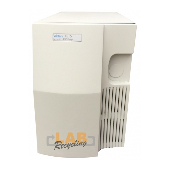
Overview of the 1500-Series Hplc Pumps
Download this manual
Waters 1500-Series
HPLC Pump and Options
Operator's Guide
715002013IVD /Revision C
Copyright © Waters Corporation 2014
All rights reserved
Table of
Contents
Previous
Page
Next
Page
1
2
3
4
5
Advertisement
Table of Contents
Troubleshooting
Troubleshooting
135
Troubleshooting pump problems
136
Need help?
Do you have a question about the 1500-Series and is the answer not in the manual?
Ask a question
Questions and answers
Related Manuals for Waters 1500-Series
Water Pump Waters 1515 Operator's Manual
Hplc pump (188 pages)
Water Pump Waters 1525 Operator's Manual
Hplc pump (188 pages)
Water Pump Waters 1525M Installation And Maintenance Manual
Hplc pump (111 pages)
Water Pump Waters 600e User Manual
Multisolvent delivery system (258 pages)
Water Pump Waters 600E Installation And Maintenance Manual
Multisolvent delivery system (162 pages)
Water Pump Waters 515 HPLC Operator's Manual
(130 pages)
Water Pump Waters P200X Overview And Maintenance Manual
High-pressure pump (80 pages)
This manual is also suitable for:
1515
1525
1525u
Table of Contents
Print
Rename the bookmark
Delete bookmark?
Delete from my manuals?
Login
Sign In
OR
Sign in with Facebook
Sign in with Google
Upload manual
Upload from disk
Upload from URL


Need help?
Do you have a question about the 1500-Series and is the answer not in the manual?
Questions and answers