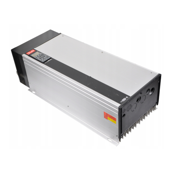
Danfoss VLT 5000 Manual
Frequency converter
Hide thumbs
Also See for VLT 5000:
- Operating instructions manual (88 pages) ,
- Instruction manual (33 pages) ,
- Application note (16 pages)
Advertisement
Abstract
This application note describes how to set up
Interbus communication between a Danfoss VLT
5000 frequency converter and Interbus CMD G4.
CMD stand for Configuration Monotoring and
Diagnostics.
VLT 5000 Interbus card
The photo shows the Interbus card which can be
installed in VLT 5001 - 5500.
LED identification
Name
Name
Name
Indicates
Indicates
Indicates
Name
Name
Indicates
Indicates
CC/CR: Cable Check.
BA
Bus Active.
RD:
Status of outgoing bus. Red
TR:
Transmit/Receive.
UL:
Power OK.
MN.50.U1.02 - VLT is a registered Danfoss trademark
VLT
Interbus connection for Bookstyle
IBS IN
RD
UL
CC/CR
TR
Color
Color
Color
On
On
On
Color
Color
On
On
Green
Incoming bus active
Green
Bus active
Outgoing bus stopped
Green
Pcp Communication running
Green
Voltage within permissible range
®
5000 and Interbus CMD
This note will describe:
Configuring of the VLT 5000 and CMD
PCP communication
All examples in this instruction are shown with a
PLC card as an Interbus master, but they are also
relevant to a PC system with an Interbus Master.
IBS OUT
BA
OFF
OFF
OFF
OFF
OFF
Incoming bus swicthed off
Bus stopped
Outgoing bus active
NO PCP Communication running
No Voltage
UL
RD
BA
CC/CR
TR
1
Advertisement
Table of Contents

Summary of Contents for Danfoss VLT 5000
- Page 1 5000 and Interbus CMD This note will describe: Abstract This application note describes how to set up Configuring of the VLT 5000 and CMD Interbus communication between a Danfoss VLT Drivecom profile 5000 frequency converter and Interbus CMD G4. PCP communication...
- Page 2 ® 5000 and Interbus CMD Configuring of the CMD and VLT 5000 Next step is to configuring the Interbus system. This The first step is to connect all Interbus slaves to the is done by clicking on the VLT symbol and pressing master and power up all units.
- Page 3 The VLT frequency converter is now set up and the Drivecom profile program can be downloaded to the PLC master. VLT 5000 has implemented the Drivecom profile in This is done by clicking with the right mouse button the Interbus software. In order to be able to run with on the Controller board.
- Page 4 Write to send the reference to the VLT frequency converter. The rpm value can now be seen in the VLT display as a reference from 0 - 100 %. The control word is now 7F Hex. Press Close. MN.50.U1.02 - VLT is a registered Danfoss trademark...
- Page 5 Write Value. The ramp up time in parameter 207 has now been changed to 10 sec. The dialog box will now show Danfoss, VLT 5000, Profile: 21. In order to be able to read in all parameters in the VLT frequency converter select Device and Read Parameter List.
- Page 6 PCD5 PCD6 PCD7 PCD3 916 PCD CONFIG. READ For controlling the VLT 5000 you can select between the FC profile or Drivecom profile (VLT parameter 512). Please have a look at the Interbus operating instructions for further description of each profile.
- Page 7 207 Ramp up time 1. 03E8 hex corresponds to 10 sek in ramp up time as this parameter has a conversion index of -2. See Configuring of the CMD and VLT 5000 for how to parametize the system. P26 Input 00FB Hex (PCD 2):...


Need help?
Do you have a question about the VLT 5000 and is the answer not in the manual?
Questions and answers