
Subscribe to Our Youtube Channel
Related Manuals for SubSurface Instruments PL-TT Series

Summary of Contents for SubSurface Instruments PL-TT Series
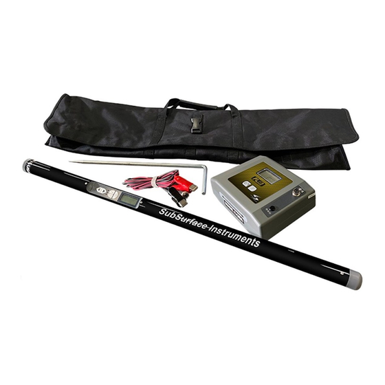
- Page 1 SERIES Pipe & Cable Locator - Track Tracer Series User Manual Instructions, Functions and Warranty Information...
- Page 2 No part of this manual may be reproduced, copied, modified or adapted, without the prior written consent of the SubSurface Instruments, Inc. Please contact SubSurface Instruments, Inc. to request permission for reproduction and use of this manual for training purposes.
-
Page 3: Table Of Contents
able of ontents eneral nformatIon Table of Contents ..........03 Gain Change Indicator ........11 Introduction ............04 Low Battery ............11 Disclaimer of Liability ......... 04 Locating the Cable or Pipe ......... 12 Important Notices ..........04 Peak Mode Locating .......... 12 Prepare for Use .......... -
Page 4: Introduction
SubSurface Instruments, Inc. Shall not be liable to Distributor, Re-Seller, or any other person for any incidental, indirect, special, exemplary or consequential damages, or injury of any type whatsoever, and caused directly or indirectly by Products sold or supplied by SubSurface Instruments, Inc.. -
Page 5: Prepare For Use
By registering your unit online at http://www.ssilocators.com/warranty-registration within one month (30 Days) of purchase, SubSurface Instruments, Inc. will extend the warranty period from 1 year to 4 years. This warranty is void if, after having received the instrument in good condition, it is subjected to abuse, unauthorized alterations or casual repair. -
Page 6: Programming Frequencies
& f hanging reset unCtions odes reQuenCies Note: This setup procedure is not required unless the user desires to change factory settings. The PL-TT operating programs and frequency sets are user programmable and can be changed at anytime through a quick selection process. -
Page 7: Pl-Vf3 Transmitter Controls And Indicators
pl-vf3 t & i ransmitter ontrols ndiCators Frequency Relative Resistance, Signal Indicators Output Signal Indicator Indicator Voltage, Current Battery Condition Indicator Inactive Port CAUTION Lethal Voltages May Be Present Frequency Selector Tx Output Jack SERIES Power On & Off & Output Signal Level Control TX OUTPUT JACK... -
Page 8: Direct Connect
ireCt onneCtion CAUTION DO NOT CONNECT TO LIVE OR ENERGIZED POWER CABLES Direct Connection is the most reliable method of signal application. This method is relatively free of interference. The greatest amount of signal strength can be achieved by this method. Low, mid, and high frequency may be used. -
Page 9: Inductive Connection
nduCtive onneCtion This method is convenient to use, and services are not interrupted. No test cords or connections are needed. The cable or pipe must have good insulation or non-conductive coating, or the operating range will be short. Turn the t on. -
Page 10: Receiver Controls & Indicators
pl-tt r & i eCeiver ontrol ndiCators Absolute Signal Strength Relative Signal Strength Polarity Bar Graph (Single bar shows Gain Setting) Displays Selected Frequency Low Battery Icon On / Off Button Displays Operation Mode selected operation and/or selected frequency available Mode Button (Hold for Depth) Frequency Button... -
Page 11: Absolute Signal Strength
bsolute ignal trength The PL-TT Locator r provides the operator with a direct measurement eceIver of the r 's signal strength. The measurement is displayed with two eceIver numerical digits located at the top of the LCD display. The measurement ranges from 0 (weak) to 99 (strong) signal strength. -
Page 12: Locating The Cable Or Pipe
oCating the able of Make sure the t is connected and in the ON position. Then move approximately 15 feet ransmItter (4.5 meters) away from the t along the path. (Move about 25 feet (7.5 meters) for the ransmItter Inductive search mode.) Hold the r so that you can easily see the LCD bar graph and the control panel. -
Page 13: Depth Measurement 45º Method
45º a epth easurement ngle ethod Move to the location you want to measure depth. Stay at least 15 feet away from the ransmItter Move the r left to right across the path until the cable is located. eceIver Mark the path on the ground as precisely as possible using the Null method. Place the r on the ground with the LCD meter facing up. -
Page 14: Locating A Sonde Or Camera Head
oCating a onde or amera Before you begin, you must choose a Sonde or Camera Head that will match the same frequency as the r to use with the PL-TT Locator . You will need a Sonde with a frequency of 512Hz eceIver eceIver... -
Page 15: Locating A Sonde
oCating a onde Hold the r , as shown below. The r antenna directly above and in line with the s eceIver onde eceIver sensitivity needs to be adjusted for a meter reading indication between 60% to 80%. is shown below. The PEAK signal is when the r The radiation pattern of the s is held onde... -
Page 16: Ferrous Metal Detection
errous etal eteCtion The PL-TT offers a ferrous metal detection capability. To select this mode press the Mode key until the Fe is shown on the LCD. The gain controls will adjust the sensitivity. This mode will only detect ferrous metals containing iron. -
Page 17: Pl-Tt Transmitter & Receiver Specifications
pl-tt s peCifiCations ransmitter Operating Frequency 200Hz - 480kHz Operating Temperature -4°F to 133º (-20ºC to +55ºC) Direct Connection Hook-up Method Inductive Coupling (with optional coupler) Transmitter Induction Load Matching Automatic from 5 Ω to 20,000 Ω Output Power 3 Watts (High) 250 Milliwatts (Low) Battery Types 8 - “C”... -
Page 18: Factory Service
The SubSurface Instruments, Inc. Model PL-TT was designed for dependable operation without periodic adjustment and/or calibration. If, however, your PL-TT is not working properly, return it to the factory for repair. A RMA (Return Material Authorization) is not required, but there is some necessary information needed to ensure your unit is repaired and returned properly. - Page 19 www.ssilocators.com SERIES...
- Page 20 AN INNOVATIVE DESIGN FORCE IN SUBSURFACE DETECTION & LOCATION SubSurface Instruments is an innovating force that engineers, manufactures and distributes high-frequency and magnetic locators, pipe and cable locators, leak detectors, leak correlators, bore hole gradiometers and specialty locators. SSI’s most recent innovation, the AML or All Materials Locator, locates buried PVC pipes, PE Pipes, plastic or nearly any other subsurface object more efficiently than ever before.
Need help?
Do you have a question about the PL-TT Series and is the answer not in the manual?
Questions and answers