Advertisement
Quick Links
Advertisement

Related Manuals for GrowSpan Flip-Top Cold Frame

Summary of Contents for GrowSpan Flip-Top Cold Frame
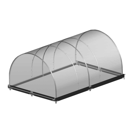
- Page 1 GrowSpan™ Flip-Top Cold Frame Photo may show a different but similar model. STK# DIMENSIONS 105144 8' W x 5' H x 6' L ©2012 GrowSpan™ 105145 8' W x 5' H x 8' L All Rights Reserved. Reproduction 105146 8' W x 5' H x 12' L is prohibited without permission.
-
Page 2: Safety Precautions
YOU MUST READ THIS DOCUMENT BEFORE YOU ASSEMBLE THE COMMERCIAL COLD FRAME. Thank you for purchasing this GrowSpan™ Flip-Top Cold Frame. These instructions include helpful hints and important information needed to safely assemble and properly maintain the cold frame. Please read these instructions before you begin. If you have any questions during the assembly, contact Customer Service at 1-800-245-9881 for assistance. -
Page 3: Assembly Procedure
CARE AND MAINTENANCE 3. Gather the tools and assistance needed to assemble the cold frame. Proper care and maintenance of your Flip-Top Cold Frame will help to ensure reliable service. The following items identify areas that must be periodically 4. Re-evaluate the location and site based on the information and precautions presented in the documentation included with the shipment. - Page 4 Important Information PICTORIAL GUIDE The following graphics and photos will help you identify the different parts of the cold frame. Consult the Quick Start Guide for additional details and diagrams. (Some parts are not shown.) 100441 FA4482B 104645 Bracket 102921B 105233 105234 104642 A-Angle...
- Page 5 Mid Rafter End Rafter End Panel OVERVIEW This section describes assembling your flip-top cold frame. The illustration below helps identify the main parts of the cold frame. 1. Locate the required parts for each assembly procedure. Main cover not shown.
-
Page 6: Assemble The Base
Assembly Instructions ASSEMBLE THE BASE After identifying the parts included with the shipment, assemble the frame using the steps below. 105237 ATTENTION: Consult the Frame Diagrams before you begin to become familiar with the parts and part locations. 1. Take one (1) 105236 end base board and connect it to one (1) 105237 105236 end base board using one (1) 104643 middle connector as shown. - Page 7 Assembly Instructions ASSEMBLE THE BASE (continued) 5. Attach the long boards to the precut end boards using the deck screws (#FAS14). Back Board ATTENTION: Note the position of the small board and the slot in the end board. Center of the back Wide Slot board is aligned with the center of the slot.
- Page 8 Assembly Instructions ASSEMBLE THE BASE (continued) 7. Locate all remaining base frame brackets and Front the screws (#FAF25P) and assemble the frame as shown on the Frame Diagram pages of these instructions. REMEMBER: Flip the frame as shown. The frame is assembled upside down and then flipped over after it is completed.
- Page 9 SQUARE THE BASE FRAME 1. After assembling the frame, flip the frame over and set the frame in place on the site. 2. With the frame positioned in the desired spot, measure diagonally from corner-to-corner and adjust the frame until both distances are equal. 3.
- Page 10 Assembly Instructions 08R105P2 ASSEMBLE THE END RAFTERS All end rafters consist of one (1) 94" straight pipe and two (2) curved sections of 08R105S1 pipe: one pipe has plain ends and one pipe has a plain end and a swaged end that is inserted into the plain end of the first pipe.
- Page 11 Assembly Instructions CUT AND INSTALL THE POLYCOR™ FOR THE END PANELS Complete the following steps to cut the end panels for the end rafters. 1. Unroll the PolyCor™ roll enough to place the rafter on a flat section of the roll. If needed, you can rest something on the roll to keep it from rolling back up as you mark the panel.
-
Page 12: Assemble Frame
Assembly Instructions ASSEMBLE FRAME 1. Locate the long, straight pipes used for the long frame tubes of the top. For the 105146 cold frame, these long tubes consist of two pipes (105P021875 and 105S123) connected and secured with a Tek screw. ATTENTION (SKU #105145 only): Cut each 105P093875 pipe to 91-3/4"... - Page 13 Assembly Instructions ASSEMBLE FRAME (continued) 7. After all pipes are seated into the proper fittings and the slip tee fittings are in place and slide freely on the long pipes, carefully lift the cover frame and set it on the base frame (E). 8.
- Page 14 Assembly Instructions INSTALL MAIN COVER Two (2) or more people are required to install the main cover. Helpful Hints: The edges of the main cover are trimmed with the white, vinyl H-channel. This trim is typically installed after the PolyCor™ is cut to the proper size and before the cover is attached to the cover frame.
- Page 15 Assembly Instructions SET THE ASSEMBLED FRAME ONTO THE BASE Back After the end panels and main cover are installed, the assembled frame can be set on the base. NOTE: The assembled frame and cover are lightweight and easily moved by wind. To prevent damage to the frame and to prevent personal injury, DO NOT attempt to set the frame on the base during windy or stormy conditions.
- Page 16 Assembly Instructions ATTACH SUPPORT PIPES AND STRAP Complete these steps: 1. Locate the remaining 105234 slip tee fittings and the two (2) lengths of straight pipe (105P094375). 2. Slide one fitting onto one straight pipe and slide that assembly onto the handle of the main cover (A).
- Page 17 Quick Start Guide QUICK START GUIDE 8' Wide Flip-Top Cold Frame *Actual dimension may vary slightly. Revision date: 10.25.12...
- Page 18 Base Frame - 105144 Install these brackets last and after the hood is in place. Length of the Front and Back Base Frame Boards is 74-1/8''. NOTE: Dimension shown is between the end frame members. Install brackets toward the inside of the brackets that secure the back board of the base frame as shown.
- Page 19 Base Frame - 105145 Install these brackets last and after the hood is in place. Length of the Front and Back Base Frame Boards is 96''. NOTE: Dimension shown is between the end frame members. Install brackets toward the inside of the brackets that secure the back board of the base frame as shown.
- Page 20 Base Frame - 105146 3" x 3" Bracket (#104645) Install this bracket last and after the hood is in place. Install this bracket last and after the hood is in place. Length of the Front and Back Base Frame Boards is 146-1/8''. Install brackets toward the inside of the brackets that secure the back NOTE: Dimension shown is...
- Page 21 Side Profile - 105144 & 105145 105144 2' 11-1/2" on-center 105145 Rafter Spacing 5' 11" on-center (Rafters) Frame Only 6' 5-1/8" (outside) (Baseboard Frame*) 3' 11-1/2" on-center Rafter Spacing 7' 11" on-center (Rafters) Frame Only 8' 5-1/8" (outside) (Baseboard Frame*) *Actual dimension may vary slightly.
- Page 22 Side Profile - 105146 105146 3' 11-1/2" on-center Rafter Spacing 11' 10-1/2" on-center (Rafters) Frame Only 12' 5-1/8" (outside) (Baseboard Frame*) *Actual dimension may vary slightly. Revision date: 10.25.12...
- Page 23 Cover Frame IMPORTANT: The assembled cover with the H-channel installed must not exceed the inside 105144 dimensions of the base frame for your cold frame. 8' W x 5' H x 6' L Verify all measurements before cutting the PolyCor™. Measure from the center of one end rafter to the center of the other end rafter and cut the PolyCor™...
Need help?
Do you have a question about the Flip-Top Cold Frame and is the answer not in the manual?
Questions and answers