Table of Contents
Advertisement
Quick Links
®
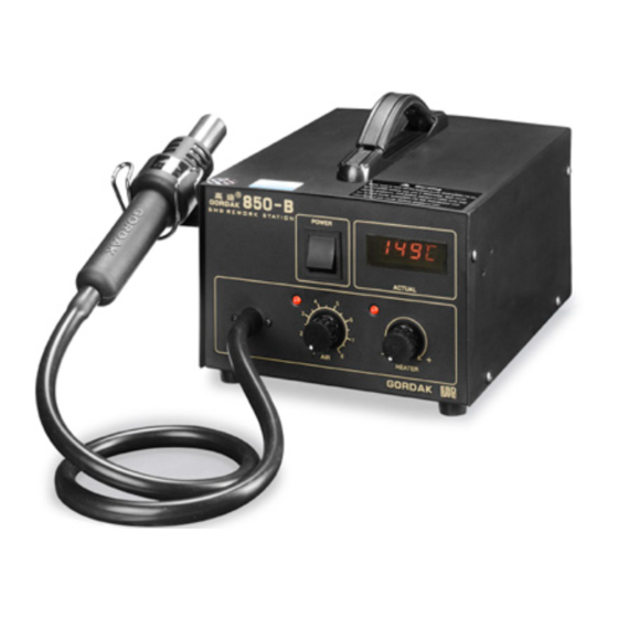
Thank you for purchasing the HAKKO 850B SMD rework
station.
The HAKKO 850B is designed to solder and desolder sur-
face mounted devices with hot air.
Please read this manual before operating the HAKKO
850B.
Keep this manual readily accessible for reference.
1. PACKING LIST 2. SPECIFICATIONS ........................... 1
3. WARNINGS, CAUTIONS AND NOTES ........................... 2
4. PART NAMES ............................................................ 3
6. OPERATION ............................................................ 5
7. MAINTENANCE / INSPECTION .................................... 7
8. TEMPERATURE DISTRIBUTION CHART ..................... 8
9. OPTIONAL NOZZLES ................................................ 11
10. PARTS LIST / HANDPIECE ..........................................12
11. WIRING DIAGRAM ...................................................15
SMD Rework Station
●
●
TABLE OF CONTENTS
STATION .............................................13
Advertisement
Table of Contents

Related Manuals for Hakko Electronics 850B


Summary of Contents for Hakko Electronics 850B
-
Page 1: Table Of Contents
SMD Rework Station ● Thank you for purchasing the HAKKO 850B SMD rework station. The HAKKO 850B is designed to solder and desolder sur- face mounted devices with hot air. Please read this manual before operating the HAKKO 850B. Keep this manual readily accessible for reference. -
Page 2: Packing List 2. Specifications
* This product does not include a nozzle. A large selection of nozzles is available for the HAKKO Power cord ............1 850B. Select the nozzle or nozzles suitable for Handpiece holder ..........1 the work to be performed. FP pick-up ............1 FP pick-up wire ............. -
Page 3: Warnings, Cautions And Notes
● Advise those in the work area that the unit can reach very high temperatures and should be considered potentially dangerous. ● Turn the power OFF when no longer using the HAKKO 850B or when leaving it unattended. ● Before replacing parts or storing the unit, allow the unit to cool and then turn the power OFF. -
Page 4: Part Names
4. PART NAMES Station POWER HEAT CONTROL AIR CONTROL Air flow control knob Temperature control knob Handpiece Accessories... -
Page 5: Preparation: Assembly And Electrical Connection
(Figure 2) (Figure 2) (Figure 3) When installing an optional nozzle to the HAKKO 850B, do C. Electrical Connection not remove this inside screw. and Power ON 1. Connect the power cord to the power receptacle on the back panel of the station. -
Page 6: Operation
6. OPERATION ● QFP Desoldering POWER 1. Adjust the air flow and temperature control knobs. HEAT CONTROL AIR CONTROL Refer to the temperature distribution chart (page 8) to adjust the air flow and temperature control knobs. Wait for Air flow control knob the temperature to stabilize for a short period of time. - Page 7 ● QFP Soldering 1. Apply the solder paste. Apply the proper quality of solder paste and install the SMD on the PWB. 2. Preheat the SMD. Refer to the photo to preheat SMD. 3. Soldering Heat the lead frame evenly. 4.
-
Page 8: Maintenance / Inspection
7. MAINTENANCE / INSPECTION ● Broken heating element A. Open the handpiece 1. Remove the three screws holding the handpiece together. (Figure 1) 2. Move the tube away from the hand- piece, as shown. 3. Open the handpiece. Disconnect the grounding wire sleeve (1) and pipe from the protruding portion of the handle. -
Page 9: Temperature Distribution Chart
The temperature distribution chart relating air-flow and temperature settings for different nozzle types provided with the HAKKO 850 are not to be used with the 850B. The 850B uses a different pump and control system and the flow-rates and temperature do not correspond. - Page 10 8. TEMPERATURE DISTRIBUTION CHART A1141B A1140B A1142B A1180B PLCC 11.5 × 14 (0.45 × 0.55) PLCC 11.5 × 11.5 (0.45 × 0.45) BQFP 17 × 17 (0.67 × 0.67) Bent Single 1.5 × 3 (0.06 × 0.12) (32 Pins) (28 Pins) Air Temperature Air Temperature Air Temperature...
- Page 11 A1258B A1259B A1260B A1261B SOP 7.6 × 12.7 (0.3 × 0.5) SOP 13 × 28 (0.51 × 1.1) SOP 8.6 × 18 (0.34 × 0.71) QFP 20 × 20 (0.78 × 0.78) Air Temperature Air Temperature Air Temperature Air Temperature Air flow Air flow Air flow...
-
Page 12: Optional Nozzles
9. OPTIONAL NOZZLES NOTE: C 1.0 (0.04) C 0.8 (0.03) C 0.8 (0.03) PLCC The size in Name/ D 1.8 (0.07) D 2.0 (0.08) D 2.0 (0.08) Specification indi- A1191 A1192 A1125B~A1129B Air flow cates the size of IC A1131~A1141B A1180B~A1189B package. -
Page 13: Parts List / Handpiece
10. PARTS LIST / HANDPIECE NOTE: Spare or repair parts do not include mounting screws, if they are not listed on the specifications. Screws must be ordered separately. Self tapping screw Nominal size Self tapping screw 3 × 12 (3) Nominal size 2.6 ×... -
Page 14: Station
10. PARTS LIST / STATION NOTE: Truss screw Spare or repair parts do not include mounting (Zn black) M4 × 5 (12) screws, if they are not listed on the specifications. Screws must be ordered separately. Item Part Part Name Specifications ①... -
Page 15: Wiring Diagram
11. WIRING DIAGRAM Pump Heating element Power switch P.W.B./ Heat control Power receptacle Triac HEAD OFFICE TEL:+81-6-6561-3225 FAX:+81-6-6561-8466 http://www.hakko.com E-mail:sales@hakko.com OVERSEAS AFFILIATES U.S.A.: AMERICAN HAKKO PRODUCTS, INC. TEL: (661) 294-0090 FAX: (661) 294-0096 Toll Free (800)88-HAKKO 4 2 5 5 6 http://www.hakkousa.com HONG KONG: HAKKO DEVELOPMENT CO., LTD.
Need help?
Do you have a question about the 850B and is the answer not in the manual?
Questions and answers