Advertisement
Table of Contents
- 1 About this Document
- 2 General Safety Instructions
- 3 Delivery Contents
- 4 Product Description
- 5 Transport and Storage
- 6 Required Tools
- 7 Inserting the Modules
- 8 Voltage Selection
- 9 Power Switch
- 10 Operation
- 11 Maintenance and Repair
- 12 Disassembly and Replacement
- 13 Environmental Protection
- 14 Extension and Conversion
- 15 Troubleshooting
- 16 Technical Data
- Download this manual
Advertisement
Table of Contents

Related Manuals for Bosch REXROTH SB356


Summary of Contents for Bosch REXROTH SB356
- Page 1 SB356 3 609 929 B67/ 2008-11...
-
Page 2: About This Document
24/124 Bosch Rexroth AGSB356 | 3 609 929 B67/2008-11 About this document Intended use The SB356 system box is a component in These instructions contain important terms of the machine directive 98/37/EC and information on the safe and appropriate is not a ready-for-use machine. The product... - Page 3 3 609 929 B67/2008-11 | SB356 Bosch Rexroth AG 25/124 professional training, knowledge, and CAUTION experience as well as their understanding of the relevant conditions pertaining to the work CAUTION indicates a potentially to be done. Qualified personnel must hazardous situation which, if not avoided, observe the rules relevant to the subject area.
- Page 4 26/124 Bosch Rexroth AGSB356 | 3 609 929 B67/2008-11 Adhere to the following instructions During assembly Make sure the relevant system component is General instructions not under pressure or voltage before Only accessories and add-on units that have assembling the product or when connecting been approved for use in Rexroth tightening and disconnecting plugs.
-
Page 5: Delivery Contents
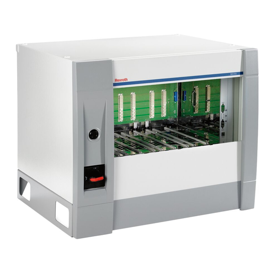
3 609 929 B67/2008-11 | SB356 Bosch Rexroth AG 27/124 Delivery contents Device description The delivery contents include: • 1 SB356 system box • 1 key • 1 suspension rail • 4 M8 DIN580 ring bolts • 1 SB356 system box operating... -
Page 6: Transport And Storage
28/124 Bosch Rexroth AGSB356 | 3 609 929 B67/2008-11 Label area Transport and storage A label area that can be used to identify the For storing and transporting the product, unit is provided on the system box (unit always observe the ambient conditions number in circuit diagram). -
Page 7: Required Tools
3 609 929 B67/2008-11 | SB356 Bosch Rexroth AG 29/124 Assembly The system boxes can either be fastened to walls or racks using the mounting brackets When installing the product, always observe on the rear or placed on their bases. The the ambient conditions specified in the installation position is horizontal. - Page 8 30/124 Bosch Rexroth AGSB356 | 3 609 929 B67/2008-11 10,8 25 25 Fig. 3: Assembly graphic with suspension rail and lift-out protection...
-
Page 9: Inserting The Modules
3 609 929 B67/2008-11 | SB356 Bosch Rexroth AG 31/124 Inserting the modules A maximum of one KE350(G IL) and 40 tightening channels can be operated in one Insert the individual modules (SE352(M), tightening system. KE350(G IL), LTU350/1, LT35x, NK350(S)) in the SB356 as shown in Fig. - Page 10 32/124 Bosch Rexroth AGSB356 | 3 609 929 B67/2008-11 CAUTION CAUTION Risk of damage to persons Risk of damage to persons and property! and property! Solely permissible protective Dangerous shock currents due to measure in accordance with insufficient PE wire connections! EN 50 178: protective grounding.
-
Page 11: Voltage Selection
3 609 929 B67/2008-11 | SB356 Bosch Rexroth AG 33/124 The mains connection is via the screw NOTE! terminals on the mains switch (Fig. 6). The user is responsible for selecting The cable fitting (Ø 8 mm - 13 mm) is suitable mains connection cables. - Page 12 34/124 Bosch Rexroth AGSB356 | 3 609 929 B67/2008-11 Terminal strips for mains connection Device connection Fig. 7: X1N4 voltage selection terminals (SB356) with connection groups G1, G2, G3 The X1N4 interface partitions represent a Table 2: Voltage selection terminals...
-
Page 13: Power Switch
3 609 929 B67/2008-11 | SB356 Bosch Rexroth AG 35/124 Power switch Mains connected loads (nominal values) The required connected load of the SB356 system box depends on the number and size 5 A max of the tightening channels to be operated. As,... - Page 14 36/124 Bosch Rexroth AGSB356 | 3 609 929 B67/2008-11 Equipping the system boxes Table 5:Tightening channel power consumption Servo ampli- Tightening Power con- A tightening channel consists of the following fier spindle sumption components: • Stationary tightening spindle or ErgoSpin...
- Page 15 3 609 929 B67/2008-11 | SB356 Bosch Rexroth AG 37/124 Commissioning CAUTION Overheating of the SB356 sys- CAUTION tem box and its components! Risk of damage to persons Damage to the system box and its and property! components from overheating...
-
Page 16: Operation
38/124 Bosch Rexroth AGSB356 | 3 609 929 B67/2008-11 Operation 6. Close the covers which were previously opened. 7. Connect to the mains. CAUTION 8. Insert the NK350/ NK350S network cou- Any dirt or liquids penetrating pler (if used). the device lead to 9. -
Page 17: Maintenance And Repair
3 609 929 B67/2008-11 | SB356 Bosch Rexroth AG 39/124 Maintenance and Disassembly and repair replacement Cleaning and care Required tools • Screwdriver CAUTION Disassembling Any dirt or liquids penetrating the device lead to Follow the warnings imprinted on the... -
Page 18: Environmental Protection
40/124 Bosch Rexroth AGSB356 | 3 609 929 B67/2008-11 Proceed as follows to disassemble the CAUTION SB356 system box: 1. First switch off the system at the power Damage to the SB356 system switch and then at the mains or pre-fuse. -
Page 19: Technical Data
3 609 929 B67/2008-11 | SB356 Bosch Rexroth AG 41/124 Technical data Table 7: Designation SB356 Order number 0 608 830 251 Input voltage 3 x 400 V ± 10%, 50 - 60 Hz (380 V to 500 V) Peak power... - Page 20 42/124 Bosch Rexroth AGSB356 | 3 609 929 B67/2008-11 Service and sales Service Sales Bosch Rexroth AG We are always the right partner when it Electric Drives and Controls comes to system know-how. Schraub- und Einpress-Systeme For any problem: Service from Rexroth Fornsbacher Str.
Need help?
Do you have a question about the REXROTH SB356 and is the answer not in the manual?
Questions and answers