Table of Contents
Advertisement
Available languages
Available languages
ITEM #1279103
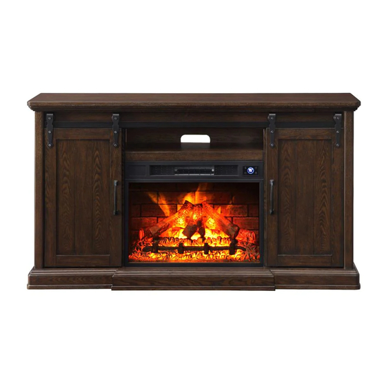
62IN BARN DOOR MANTLE WITH
3D FLAME AND WIFI SMART
ELECTRIC FIREPLACE
MODEL#F18-I-008-018C
Español p. 20
ATTACH YOUR RECEIPT HERE
Purchase Date
Serial Number
Questions, problems, missing parts? Before returning to your retailer, call our customer
service department at 1-877-355-3326 or 1-925-820-8478, 9 a.m. - 4 p.m., EST, Monday -
Friday. Email: service@febointernational.com
1
Advertisement
Table of Contents

Related Manuals for Febo Flame F18-I-008-018C


Summary of Contents for Febo Flame F18-I-008-018C
- Page 1 ITEM #1279103 62IN BARN DOOR MANTLE WITH 3D FLAME AND WIFI SMART ELECTRIC FIREPLACE MODEL#F18-I-008-018C Español p. 20 ATTACH YOUR RECEIPT HERE Purchase Date Serial Number Questions, problems, missing parts? Before returning to your retailer, call our customer service department at 1-877-355-3326 or 1-925-820-8478, 9 a.m. - 4 p.m., EST, Monday -...
-
Page 2: Package Contents
PACKAGE CONTENTS PART DESCRIPTION QUANTITY PART DESCRIPTION QUANTITY Center Panel Adjustable Shelf Connecting Wood Removable Back Panel Left Middle Panel Left Door Right Middle Panel Right Door Bottom Frame Electric Insert Left Side Panel Remote Control Right Side Panel No-tool Assembly Hardware (Preassembled To Left Side Panel (F), Front Rail Left Middle Panel (C), Right Middle Panel... - Page 3 HARDWARE CONTENTS (not shown actual size) Spring Washer Short Hex Bolt Qty. 10 Flat Washer Qty. 8 Wood Dowel Qty. 14 Qty. 24 Long Hex Bolt Hex Wrench Qty. 10 Qty. 1 Plastic Pad Shelf Pin Qty. 2 Qty. 16 Handle Bolt Long Screw Qty.
-
Page 4: Safety Information
SAFETY INFORMATION Please read and understand this entire manual before attempting to assemble, operate or install the product. When using electrical appliance, basic precautions should always be followed to reduce the risk of fire, electric shock and injury to persons including the following: •... - Page 5 WARNING • Do not fully tighten the bolts on the assembly until mantel is completed. Positioning of the mantel pieces during assembly will be easier if there is some flexibility between the different pieces. Tighten all bolts after the assembly is complete and before the insert is set inside. •...
- Page 6 ASSEMBLY INSTRUCTIONS Note: Do not fully tighten the bolts on the assembly until mantel is completed. Assemble the item as close to its final location as possible. 1. Attach connecting wood (B) to each side of center panel (A) using long hex bolt (CC), spring washer (DD) and flat washer (EE).
- Page 7 ASSEMBLY INSTRUCTIONS 3. Insert wood dowels (AA) into bottom frame (E). Line up holes on left middle panel (C) and right middle panel (D) with wood dowels (AA) and attach to bottom frame (E) by closing no-tool assembly hardware(R). Hardware Used Wood Dowel 4.
- Page 8 ASSEMBLY INSTRUCTIONS 5. Insert wood dowels (AA) into left middle panel (C) and right middle panel (D). Line up holes on front rail (H) with wood dowels (AA) and attach to left side panel (F) and right side panel (G) using long hex bolt (CC), spring washer (DD) and flat washer (EE).
- Page 9 ASSEMBLY INSTRUCTIONS 7. Attach back rail (J) to top frame (K) with wood dowels (AA) and long screw (JJ). Tighten with Philips screwdriver. Front Insert wood dowels (AA) into left side panel (F), left middle panel (C), right middle panel (D) and right Back side panel (G).
- Page 10 ASSEMBLY INSTRUCTIONS 9. Insert the glides (S) into the groove on bottom frame (E). Hang sliding hardware (GG) on the metal rail so the wheel rolls smoothly. Align the holes in sliding hardware (GG) with the holes in the door and attach sliding hardware (GG) to the door with short hex bolt (BB).
- Page 11 ASSEMBLY INSTRUCTIONS 11. From backside of mantel assembly, attach removable back panel (M) into groove on center panel (A). 12. Still from the backside of the assembly, and with the assistance of another person, insert the electric insert (P) into the opening. Then, attach rear rail (T) to bottom center panel (A) and bottom frame (E) using long screw (JJ).
- Page 12 ASSEMBLY INSTRUCTIONS 13. Attach the tipping prevention device (NN) to the back top frame (K) with flat washer (EE) and short screw (OO). Tighten with Philips Screwdriver. Place the mantel in the desired location and mark the wall behind the tipping prevention device (NN). Remove NOT INCLUDED the mantel and drill a hole for the wall anchor (PP) at the marked location.
- Page 13 OPERATING INSTRUCTIONS 1. Ensure all controls are in the “OFF” position before plugging the appliance into a properly grounded electrical outlet. This appliance is for use on 120 volts. The appliance has a 3-prong grounded plug. If your electrical outlet has only 2 slots, you will have to use an adapter to convert from the 3-prong power cord to a Matel Screw 2-slot receptacle.
- Page 14 OPERATING INSTRUCTIONS 4. Power: Push button to turn on or turn off. If ON, the digital display screen will show the room temperature, the flame is on. If OFF, all functions except Timer will be restored at the next power ON. Note: Unplugging the unit will reset all functions.
- Page 15 OPERATING INSTRUCTIONS 6. Heater: Press and hold the button for 1.5 seconds to activate or deactivate the heater function. The system will start the default temperature setting at 80°F/27°C. There are 7 adjustable heat levels, ranging from 90°F/32°C to 60°F/16°C. Press the button again to adjust the heat levels, or press the UP or DOWN button on the remote control to adjust the levels, noting each level increases or decreases the temperature by 5°F.
-
Page 16: Care And Maintenance
OPERATING INSTRUCTIONS 8. Buttons on the Remote Control (Q) have the same functions as those on the Control Panel except Heater and Timer. Heater: On the remote control (Q), press this button immediately activate or deactivate the heater function. Press the UP or DOWN button to adjust the heat level. Timer: On the remote control (Q), press this button immediately activate or deactivate the timer function. -
Page 17: Troubleshooting
TROUBLESHOOTING POSSIBLE CAUSE SOLUTION PROBLEM 1. Dimmer control button 1. Push flame button to increase light. is set too low. 2. Contact customer service center. 2. LED strip not Simulated flame 3. Remove screws holding back panel functioning. effect is dim or not in place and remove back panel. -
Page 18: Replacement Parts List
REPLACEMENT PARTS LIST For replacement parts, call our customer service department at 1-877-355-3326 or 1-925-820-8478, 9 a.m. - 4 p.m., EST, Monday - Friday. Email: service@febointernational.com PART DESCRIPTION PART # Remote Control 2019-411001 Wood Dowel 2019-401001 Short Hex Bolt 2019-402001 Long Hex Bolt 2019-402002 Spring Washer... - Page 19 REPLACEMENT PARTS LIST For replacement parts, call our customer service department at 1-877-355-3326 or 1-925-820-8478, 9 a.m. - 4 p.m., EST, Monday - Friday. Email: service@febointernational.com Printed in Vietnam...
- Page 20 REPISA PARA CHIMENEA TIPO PUERTA DE GRANERO DE 157,48 CM CON LLAMA 3D Y CHIMENEA ELÉCTRICA INTELIGENTE CON WIFI MODELO#F18-I-008-018C ADJUNTE SU RECIBO AQUI Número de serie Fecha de compra ¿Preguntas, problemas, piezas faltantes? Antes de volver a la tienda, llame al Servicio al Cliente al 1-877-355-3326 o 1-925-820-8478, de lunes a viernes de 8 a.m.
-
Page 21: Contenido Del Paquete
CONTENIDO DEL PAQUETE PIEZA DESCRIPCIÓN CANTIDAD PIEZA DESCRIPCIÓN CANTIDAD Panel central Repisa ajustable Madera de conexión Panel posterior desmontable Panel central izquierdo Puerta izquierda Panel central derecho Puerta derecha Estructura inferior Accesorio eléctrico Panel izquierdo Control remotoNo-tool Panel derecho Aditamentos de ensamblaje que no (Preensamblados en el panel necesitan herramientas Riel frontal... - Page 22 ADITAMENTOS (no se muestran en tamaño real) Arandela de resorte Perno Arandela hexagonal corto Cant. 10 plana Espiga de Cant. 8 madera Cant. 14 Cant. 24 Perno hexagonal Llave largo hexagonal Cant. 10 Cant. 1 Almohadilla plástica Pasador de repisa Cant.
-
Page 23: Información De Seguridad
INFORMACIÓN DE SEGURIDAD Lea y comprenda completamente este manual antes de intentar ensamblar, usar o instalar el producto. Cuando utilice electrodomésticos, siempre tome medidas de precaución básicas para reducir el riesgo de incendios, descargas eléctricas y lesiones personales, incluidas las siguientes: •... - Page 24 GUARDE ESTAS INSTRUCCIONES ADVERTENCIA • No apriete completamente los pernos en el ensamble hasta que la repisa para chimenea esté terminada. Será más fácil colocar las piezas de la repisa para chimenea durante el ensamblaje si existe mayor flexibilidad entre las distintas piezas. Apriete todos los pernos después de que el ensamble esté...
-
Page 25: Instrucciones De Ensamblaje
INSTRUCCIONES DE ENSAMBLAJE NOTA: no apriete completamente los pernos en el ensamble hasta que la repisa para chimenea esté terminada. Ensamble el artículo lo más cercano a su ubicación final que sea posible. 1. Fije la madera de conexión (B) a cada lado del panel central (A) con el perno hexagonal largo (CC), una arandela de resorte (DD) y una arandela plana (EE). - Page 26 INSTRUCCIONES DE ENSAMBLAJE 3. Coloque las espigas de madera (AA) en la estructura inferior (E). Alinee los orificios del panel central izquierdo (C) y del panel central derecho (D) con las espigas de madera (AA) y fije a la estructura inferior (E) cerrando los aditamentos de montaje que no necesitan herramientas (R).
- Page 27 INSTRUCCIONES DE ENSAMBLAJE 5. Introduzca espigas de madera (AA) en el panel central izquierdo (C) y el panel central derecho (D). Alinee los orificios del riel frontal (H) con las espigas de madera (AA) y fije al panel lateral izquierdo (F) y al panel lateral derecho (G) con un perno hexagonal largo (CC), una arandela de resorte (DD) y una arandela plana (EE).
- Page 28 INSTRUCCIONES DE ENSAMBLAJE 7. Fije el riel posterior (J) a la estructura superior (K) con espigas de madera (AA) y un tornillo largo (JJ). Apriete con un destornillador Phillips. Front Inserte espigas de madera (AA) en el panel lateral izquierdo (F), el panel central izquierdo (C), el panel Back central derecho (D) y el panel lateral derecho (G).
- Page 29 INSTRUCCIONES DE ENSAMBLAJE 9. Inserte los deslizadores (S) en la ranura de la estructura inferior (E). Cuelgue los aditamentos deslizantes (GG) en el riel de metal de modo que la rueda se deslice suavemente. Alinee los orificios de los aditamentos deslizantes (GG) con los orificios de la puerta y fije los aditamentos deslizantes (GG) a la puerta con un perno hexagonal corto (BB).
- Page 30 INSTRUCCIONES DE ENSAMBLAJE 11. Desde el lado posterior del ensamble de repisa para chimenea, instale los paneles posteriores desmontables (M) en la ranura de la panel central (A). 12. Continuando desde la parte posterior del ensamble y con la ayuda de otra persona, inserte el accesorio eléctrico (P) en la abertura.
- Page 31 INSTRUCCIONES DE ENSAMBLAJE 13. Fije el dispositivo de prevención de vuelcos (NN) a la estructura superior posterior (K) con una arandela plana (EE) y un tornillo corto (OO). Apriete con un destornillador Phillips. Coloque la repisa para chimenea en el lugar deseado y marque la pared NOT INCLUDED detrás del dispositivo de prevención de vuelcos (NN).
-
Page 32: Instrucciones De Uso
INSTRUCCIONES DE USO 1. Compruebe que todos los controles estén en posición “OFF” (apagado) antes de enchufar el electrodoméstico en un tomacorriente con la debida puesta eléctrica a tierra. Este electrodoméstico está diseñado para su uso en 120 voltios. Este electrodoméstico tiene un enchufe Tornillo para metal con puesta a tierra de 3 clavijas. - Page 33 INSTRUCCIONES DE USO 4. Encendido: presione el botón para encender o apagar. Si está encendida, la pantalla digital mostrará la temperatura ambiente y si la llama está encendida. Si está en la posición OFF (apagado), el todas las funciones excepto Temporizador se restablecerá la próxima vez que se encienda.
- Page 34 INSTRUCCIONES DE USO 6. Calentador: mantenga presionado el botón durante activar o desactivar la función 1,5 segundos para de calentador. El sistema iniciará la configuración de temperatura en 26,6 °C. Existen 7 niveles regulables de calor; desde 32,2 °C a 15,5 °C. Presione el botón nuevamente para ajustar los niveles de calor o presione UP (Arriba) o DOWN (Abajo) en el control el botón...
-
Page 35: Cuidado Y Mantenimiento
INSTRUCCIONES DE USO 8. Los botones del control remoto (Q) tienen las mismas funciones del panel de control, excepto Calentador y temporizador. Calentador: en el control remoto (Q), si presiona este botón inmediatamente se activa o desactivar esta función del calentador. Presione el botón UP (Arriba) o DOWN (Abajo) para ajustar los niveles. -
Page 36: Solución De Problemas
SOLUCIÓN DE PROBLEMAS LAS POSIBLES RAZONES SOLUCIÓN PROBLEMA 1. Presione el botón de llama, luego 1. El botón regulador se aumente el brillo con el botón hacia arriba. ajustó demasiado bajo. 2. Póngase en contacto con el Centro de 2. La tira del LED no Servicio al Cliente. -
Page 37: Lista De Piezas De Repuesto
LISTA DE PIEZAS DE REPUESTO Para obtener piezas de repuesto, llame al Servicio al Cliente al 1-877-355-3326 o 1-925-820-8478, de lunes a viernes de 9 a.m. a 4 p.m., hora estándar del Este. Correo electrónico: service@febointernational.com PIEZA DESCRIPCIÓN PIEZA # Control remoto 2019-411001 Espiga de madera... - Page 38 LISTA DE PIEZAS DE REPUESTO Para obtener piezas de repuesto, llame al Servicio al Cliente al 1-877-355-3326 o 1-925-820-8478, de lunes a viernes de 9 a.m. a 4 p.m., hora estándar del Este. Correo electrónico: service@febointernational.com Impreso en Vietnam...
- Page 39 MAXIMUM LOAD 80 LBS. MAXIMUM LOAD 20 LBS. MAXIMUM LOAD 20 LBS. MAXIMUM LOAD 20 LBS. ITEM#1279103/MODEL#F18-I-008-018C DISTRIBUTION: EASY TOP (HK) ENTERPRISES LTD ADDRESS: 15TH FLOOR, JINLIAN COMMERCIAL CENTER, NO. 2 JINXIU ROAD, CHANGAN TOWN, DONGGUAN CITY, GUANGDONG PROVINCE, CHINA...
Need help?
Do you have a question about the F18-I-008-018C and is the answer not in the manual?
Questions and answers
Need a Manuel for model #ZHS-30-A S#133005426522
The manual for Febo Flame model ZHS-30-A is the F18-I-008-018C Febo Flame Manual.
This answer is automatically generated
Do you have insert for 10IN-28-007
What is the cost of the insert for the product?
What does an insert replacement cost? Model #F18-I-008-018C