Table of Contents
Advertisement
Quick Links
ECM DIO8 eBUS Digital I/O Control Module • Setup Guide
The Extron ECM DIO8 is a compact digital I/O module for Extron eBUS
an IPCP Pro control processor and provides an interface with a variety of I/O devices, including sensors, and contact closure
buttons. The ECM DIO8 provides eight digital I/O ports that can be configured or programmed by Extron software. There is also a
24 VDC (100 mA maximum) output to provide power to a sensor.
The module connects to the Extron IPCP Pro control processor or other eBUS devices using a single cable that carries both
power and communication. Extron recommends the STP20-2 or STP20P-2 cable.
The ECM DIO8 mounts inside a US 1-gang, Flex55, EU, or MK enclosure. It can also be mounted on any flat surface, using the
provided dual-lock fastener.
Front Panel Features
BUS ID
M
L
A
S
S
ECM DIO8
B
B
B
C
D
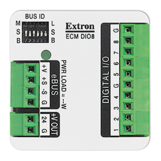
Front Panel Features of ECM DIO8
Figure 1.
A
BUS ID DIP Switches — Up to eight eBUS devices can be connected to one control processor. Each eBUS device
connected to the same IPCP Pro control processor must have a unique BUS ID, which is set using BUS ID DIP switches (see
Step 2 — BUS ID setup
B
Status LED — The ECM DIO8 has a three-color LED (red, amber, and green) that provides diagnostic information about the
connection, communication, and power status of the module (see
page 12).
C
eBUS Port — This four-pole captive screw connector provides power to the ECM DIO8 and also provides communication
between the ECM DIO8 and a control processor and other eBUS devices.
D
Voltage Output — This two-pole captive screw connector can provide 24 VDC to a sensor (100 mA maximum output
current).
E
Digital I/O Ports — This 10-pole captive screw connector provides an interface for up to eight digital I/O devices, with two
ground connections.
Overview
The following sections describe:
Digital I/O Uses
on the next page
•
Before You Start
(see page 3)
•
Downloading Software
•
Installation
(see page 4)
•
Step 1 — Mounting the ECM DIO8
•
Step 2 — BUS ID setup
•
Step 3 — Connecting Cables
•
Step 4 — Configuring the System
•
Step 5 — Testing and Troubleshooting the System
•
E
on page 6).
(see page 3)
(see page 4)
(see page 6)
(see page 9)
(see page 12)
®
-enabled control systems. The module connects to
Step 5 — Testing and Troubleshooting the System
(see page 12)
Product Category
on
1
Advertisement
Table of Contents

Related Manuals for Extron electronics ECM DIO8


Summary of Contents for Extron electronics ECM DIO8
- Page 1 The module connects to the Extron IPCP Pro control processor or other eBUS devices using a single cable that carries both power and communication. Extron recommends the STP20-2 or STP20P-2 cable. The ECM DIO8 mounts inside a US 1-gang, Flex55, EU, or MK enclosure. It can also be mounted on any flat surface, using the provided dual-lock fastener.
-
Page 2: Digital Input
Digital I/O Uses The ECM DIO8 has eight digital I/O ports, which can be connected to sensors or contact closure buttons. Each port supports either digital inputs or digital outputs, which is selectable by software (see the Global Configurator Plus and Professional Help File or the Global Scripter Help File). - Page 3 Before You Start Downloading Software You can use Global Configurator Plus and Professional to configure the system or Global Scripter to program the eBUS system (see the appropriate help file for information about using the software). To download the software: Go to www.extron.com.
-
Page 4: Installation
Wall mounting with a junction box The ECM DIO8 can be mounted in any standard 1-gang junction box (US, Flex55, EU, or MK). The junction boxes must be purchased separately and installed by following the instructions provided by the manufacturer. -
Page 5: Mounting To A Flat Surface
Plenum-space mounting The ECM DIO8 is not plenum rated. It can be installed in a non-plenum area of the ceiling using the mounting bracket. If it is installed in a plenum space it must be mounted in a closed junction box with plenum rated cable or conduit for all connections. -
Page 6: Dip Switch
ECM DIO8 Digital I/O Control Module • Setup Guide (Continued) Step 2 — BUS ID setup Various combinations of the six DIP switches being set to On or Off, provide 64 addresses: 0 is a reserved eBUS ID and the configurable eBUS ID range is 1 through 63 (see the table on the two following pages). - Page 7 Setting eBUS ID numbers In the table below, a DIP switch setting shown as 0 is equivalent to Off. A DIP switch setting shown as 1 is equivalent to On. NOTE: The ID number 0 (switch setting 000000) is reserved for the control processor and cannot be used by an eBUS device. DIP Switch Setting Decimal DIP Switch Setting...
- Page 8 ECM DIO8 Digital I/O Control Module • Setup Guide (Continued) DIP Switch Setting Decimal DIP Switch Setting Decimal Value Value 1 2 3 4 5 6 1 2 3 4 5 6 1 2 3 4 5 6 1 2 3 4 5 6...
- Page 9 Step 3 — Connecting Cables The ECM DIO8 can be powered by an eBUS connection to a control processor, distribution hub, or a 12 VDC power supply. Do not connect power to either unit until you have read these Attention notifications.
- Page 10 ECM DIO8 Digital I/O Control Module • Setup Guide (Continued) Pigtail Wire (Ground) Wire Nut Wire Nut Connecting a Ground wire to the ECM DIO8 Figure 12. Cut about 2" (51 mm) from the end of the cable. Save the ground wire for use as a pigtail.
- Page 11 IPCP Pro 250 control processor. The +12 VDC wire runs from the control processor to the ECM DIO8. The lower panel of figure 13 shows the ECM DIO8 is powered by the PS1220EB. In this case, the cable between the IPCP Pro 250 control processor and the power supply has the +12 VDC wire removed.
-
Page 12: Step 4 - Configuring The System
If required, the ECM DIO8 can provide power (24 VDC, 100 mA maximum) to Extron or third-party sensors. Connect the +V Out 2-pole captive screw to the sensor. The ground (G) terminal of the ECM DIO8 must be connected to the ground terminal of the sensor and the voltage output (24) terminal of the ECM DIO8 must be connected to the voltage input terminal of the sensor.
Need help?
Do you have a question about the ECM DIO8 and is the answer not in the manual?
Questions and answers