Table of Contents
Advertisement
Quick Links
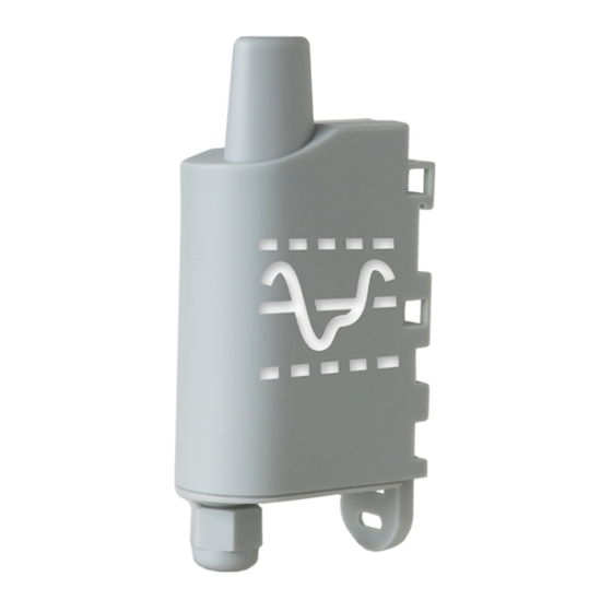
sigfox ANALOG PWR
Transceiver Analog/Digital Interface
Ce Guide utilisateur s'applique à partir des versions logicielles suivantes :
This User Guide applies from the following firmware versions:
Version RTU : V01.01.01
Version APP : V01.03.04
adeunis ®
283 rue Louis Néel - Parc Technologique Pré Roux
38920 CROLLES - France
Tel. : +33 (0)4 76 92 07 77 - Fax : +33 (0)4 76 04 80 87
www.adeunis.com
sales@adeunis.com
Guide utilisateur / User Guide
Version 2.0.0
Advertisement
Table of Contents

Related Manuals for Adeunis RF sigfox ANALOG PWR


Summary of Contents for Adeunis RF sigfox ANALOG PWR
- Page 1 ANALOG PWR Transceiver Analog/Digital Interface Guide utilisateur / User Guide Version 2.0.0 Ce Guide utilisateur s’applique à partir des versions logicielles suivantes : This User Guide applies from the following firmware versions: Version RTU : V01.01.01 Version APP : V01.03.04 adeunis ®...
- Page 2 ANALOG PWR - Guide utilisateur / User guide version V2.0.0 ENGLISH Page of 86...
-
Page 3: Products And Regulatory Information
ANALOG PWR - Guide utilisateur / User guide version V2.0.0 PRODUCTS AND REGULATORY INFORMATION Document Informa- tion Title sigfox ANALOG PWR - User Guide Sub-title Document type User Guide Version 2.0.0 This document applies to the following products : Référence... -
Page 4: Eu Declaration Of Conformity
ANALOG PWR - Guide utilisateur / User guide version V2.0.0 EU Declaration of Conformity adeunis 283 rue LOUIS NEEL 38920 Crolles, France 04.76.92.01.62 www.adeunis.com Declare that the DoC is issued under our sole responsibility and belongs to the following product:... - Page 5 ANALOG PWR - Guide utilisateur / User guide version V2.0.0 INTRODUCTION All rights to this manual are the exclusive property of adeunis®. All rights reserved. Copying this manual (wit- hout written permission from the owner) via printing, copying, recording or by any other means, translating this manual (in full or partially) into any other language, including all programming languages, using any electrical, mechanical, magnetic or optical devices, manually or any by other methods, is prohibited.
-
Page 6: Environmental Recommendations
ANALOG PWR - Guide utilisateur / User guide version V2.0.0 ENVIRONMENTAL RECOMMENDATIONS All superfl uous packaging materials have been eliminated. We have done everything possible to make it easy to separate the packaging into three types of materials: cardboard (box), expanded polystyrene (fi ller material) and polyethylene (packets, foam protective sheets). Your device is composed of materials that can be recycled and reused if it is dismantled by a specialist company. Please observe local regulations concerning the manner in which waste packaging material, used batteries and your obsolete equipment are disposed of. -
Page 7: Recommandations Regarding Use
ANALOG PWR - Guide utilisateur / User guide version V2.0.0 RECOMMANDATIONS REGARDING USE • Before using the system, check that the power supply voltage shown in the user manual corresponds to your supply. If it doesn’t, please consult your supplier. -
Page 8: Product Presentation
• This product meets the needs of users who need to remotely monitor data of any kind (temperature, pressure, level, humidity, CO², speed, brightness, opening, etc.) • The use of the sigfox protocol allows you to integrate the sigfox ANALOG PWR into any network that is already deployed. -
Page 9: Electronic Card
ANALOG PWR - Guide utilisateur / User guide version V2.0.0 1.2. Dimensions Values in millimetres 49,50 1.3. Electronic card 49,50 Internal antenna Internal battery RF module sigfox protocol 49,50 USB port for product configu- ration Screw terminals for connecting sensors Page of 86... -
Page 10: Technical Specifications
ANALOG PWR - Guide utilisateur / User guide version V2.0.0 1.4. Technical Specifications 1.4.1 General characteristics Parameters Value Power supply 5-36V DC Maximal power 90mA Working temperature -25°C / +70°C Dimensions 105 x 50 x 27mm Weight Casing IP 67... -
Page 11: Digital Interfaces
ANALOG PWR - Guide utilisateur / User guide version V2.0.0 1.4.2.02 Interfaces 0-10V The schematic diagram of the 0-10V interfaces is the following: Absolute maximum values Units Minimum input voltage Maximum input voltage Electrical characteristics Units Minimum input voltage... -
Page 12: Power Supply
ANALOG PWR - Guide utilisateur / User guide version V2.0.0 Electrical characteristics Units Minimum input voltage Maximum input voltage Equivalent input resistance kΩ Input frequency High input level current consumption µA Low input level current consumption µA 1.4.2.04 Power supply... -
Page 13: Global Operation
ANALOG PWR - Guide utilisateur / User guide version V2.0.0 PRODUCT OPERATION 2.1. Global Operation Important: adeunis® use the most significant byte first format. The product has several operating modes: PARK MODE Presence of a magnet on the product >6s Command sending by serial link COMMAND MODE OPERATING MODE 2.1.1... -
Page 14: Application Operation
ANALOG PWR - Guide utilisateur / User guide version V2.0.0 2.2. Application operation 2.2.1 Periodic transmission The product allows the measurement and the periodic transmission of the values of the sensors according to the following diagram: Product in standby... - Page 15 ANALOG PWR - Guide utilisateur / User guide version V2.0.0 2.2.2 Transmission on exceeding of the threshold The product allows detection threshold overrun (upper and lower) for each sensor according to the following dia- gram: Product in standby Period...
- Page 16 ANALOG PWR - Guide utilisateur / User guide version V2.0.0 Explanation of thresholds and hysteresis: high threshold High threshold - high threshold hysteresis Sensor value Low threshold + low threshold hysteresis Low threshold Low alarm enabling Low alarm disabling...
- Page 17 ANALOG PWR - Guide utilisateur / User guide version V2.0.0 S325 Decimal 100 000 The value of the hysteresis of the high thres- hold of channel A is: 100 000x10=1 000 000nA so 1mA S326 Decimal 600 000 The value of the low threshold of channel A is:...
- Page 18 ANALOG PWR - Guide utilisateur / User guide version V2.0.0 Register Value encoding Value Result S301 Decimal Event mode S320 Hexadecimal 0x02 Channel A configured for a sensor 4-20mA S322 Hexadecimal 0x01 Channel B configured for a sensor 0-10V S321 Hexadecimal 0x1C Channel A: No threshold detection Event detection on digital input on rising and falling edges •...
-
Page 19: Operation Of The Leds
ANALOG PWR - Guide utilisateur / User guide version V2.0.0 2.2.5 TEST Mode This mode allows the user to perform tests of the product more quickly by reducing the time scales of the produc- tion mode and modifying the behaviour of the LEDs. -
Page 20: Device Configuration
ANALOG PWR - Guide utilisateur / User guide version V2.0.0 DEVICE CONFIGURATION The device can be configured using the USB connector. This connection allows you to communicate with the device via a virtual com port and to transmit AT commands in order to modify the parameters of the device. WARNING : the USB connection does not supply power to the product, it induces a consumption of the product as long as the one is connected. -
Page 21: Command Mode
ANALOG PWR - Guide utilisateur / User guide version V2.0.0 3.2. Command mode Use a COM port terminal in order to communicate with the device. We use the HERCULES COM port soft terminal available to download for free by clicking on the following link: http://www.hw-group.com/devices/hercules/index_en.html •... - Page 22 ANALOG PWR - Guide utilisateur / User guide version V2.0.0 3.3. AT commands A command starts with 2 ASCII characters: “AT”, followed by one or more characters and data (see the list below for the syntax of AT commands available on the modem).
-
Page 23: Description Of The Registers
ANALOG PWR - Guide utilisateur / User guide version V2.0.0 3.4. Description of the registers On switching on the product works according to the last saved configuration (Factory Configuration if it is the first start, or if this configuration has not been changed). Commands such as Modification TTY<n>=<M> or ATR allow you to change the content of the registers: <n> representing the number of the register and <m> the value to be assigned. This latter is either a decimal value or a hexadecimal value consistent with the «encoding»... - Page 24 ANALOG PWR - Guide utilisateur / User guide version V2.0.0 Configuration of the channel A Hexadecimal Default : 0x00 sensor Bits 0 à 3 : Type • 0 = none • 1 = 0-10 V • 2 = 4-20 mA...
-
Page 25: Network Registers
ANALOG PWR - Guide utilisateur / User guide version V2.0.0 Low threshold value channel A Decimal Default : 0 For a 4-20mA sensor: • Unit: x 10nA • Min/Max values: 400 000 à 2 000 000 E.g.: if S326=600 000, the low threshold will have a value of 600000x10=6 000 000nA i.e. -
Page 26: Description Of The Frames
ANALOG PWR - Guide utilisateur / User guide version V2.0.0 DESCRIPTION OF THE FRAMES 4.1. Uplink frames All of the uplink frames of the product to the network (uplink) always have a size of 11 bytes. 4.1.1 Fixed bytes... - Page 27 ANALOG PWR - Guide utilisateur / User guide version V2.0.0 • Byte 7: register 323, configuration of the events on channel B • Byte 8: register 306, product mode (Park, Standard (production), Test or REPLI) In the example in grey this gives: • Byte 2=0x48: register 300, Keep Alive frame issued every 12 hours •...
- Page 28 ANALOG PWR - Guide utilisateur / User guide version V2.0.0 8,000,000 µV i.e. 8V • Bytes 5 to 7=0x0F4240=100,000 in decimal: register 329, the value of the high hysteresis for channel B is: 1,000,000µV i.e. 1V Code Status PAYLOAD...
- Page 29 ANALOG PWR - Guide utilisateur / User guide version V2.0.0 • Byte 6=0x01: register 322, channel B configured for a 0-10V sensor • Bytes 7 to 9=0x4C4B40=5,000,000 in decimal i.e. a value measured on channel B of: 5,000,000 µV i.e. 5V 4.1.5 Reply frame to a register value request in a downlink frame Following reception of a downlink frame with the code 0x40, the frame 0x31 is transmitted.
- Page 30 ANALOG PWR - Guide utilisateur / User guide version V2.0.0 4.1.7 Summary of the conditions of the transmission of the uplink frames The table below summarizes the conditions of the transmission of the different uplink frames: Code Description Sending conditions 0x10 Product configuration data frames • Start-up of the product 0x11 • Exit from the configuration mode (AT Command) 0x12 •...
-
Page 31: Downlink Frames
ANALOG PWR - Guide utilisateur / User guide version V2.0.0 4.2. Downlink frames SIGFOX technology allows up to 4 downlink messages to be transmitted (from the network to the product) per day depending on the subscription. A downlink message is in fact an acknowledgement of receipt of an uplink frame with a request for acknowledge- ment. - Page 32 ANALOG PWR - Guide utilisateur / User guide version V2.0.0 4.2.2 Network configuration request frame This frame allows to inform the product via the network that it must resend the network configuration uplink frame (0x20). Code PAYLOAD 0x02 4.2.3 Specific register value request frame This frame (0x40) allows to inform the product via the network that it must send the values of specific registers in a uplink frame (0x31). … Code PAYLOAD 0x40 CONFID1 CONFID2 CONFID3 CONFID7 Description of the frame: •...
-
Page 33: Preparation And Start-Up
Analog sensors require an electric power supply. The power supply of the sensor may be the same as that of the sigfox ANALOG PWR, provided that the supply voltage is compatible with both. Page of 86... - Page 34 ANALOG PWR - Guide utilisateur / User guide version V2.0.0 5.4. Wiring of analog sensors Example of Analog sensor(s) assembly Electric power supply example: 10-29 V, 100 mA (depending on External power supply + the sensor’s needs External power supply -...
-
Page 35: Closing The Casing
ANALOG PWR - Guide utilisateur / User guide version V2.0.0 5.6. Closing the casing Once previous stages have been carried out, you can close the casing of the sigfox ANALOG PWR Procedure: 1. Make sure that the seal is properly positioned on the base 2. -
Page 36: Starting Up The Product Using A Magnet
The start-up is carried out using a magnet which you place on the upper part of the product (cf. the diagram below). The magnet must be held in position for at least 6 seconds so as to confirm the start-up of the product. When the magnet is well detected, the green LED lights up for 1 second. Once the sigfox ANALOG PWR unit validates its start-up, it immediately transmits status frames followed by a data frame (according the defined periodicity). Position of the magnet... -
Page 37: Installation And Use
ANALOG PWR - Guide utilisateur / User guide version V2.0.0 INSTALLATION AND USE 6.1. Correct positioning of the product There are two key rules for optimising radio ranges. • The first one consists of positioning your product as high as possible. • The second one consists of limiting the number of obstacles in order to avoid excessive attenuation of the radio wave. -
Page 38: Fixing With Screws
ANALOG PWR - Guide utilisateur / User guide version V2.0.0 To optimise fastening onto a tube or mast, we recom- Pins mend you remove the Rail-DIN locking/unlocking lever. To remove it, pull the lever down until the locking pins... -
Page 39: Document History
ANALOG PWR - Guide utilisateur / User guide version V2.0.0 6.2.3 DIN-Rail fixing This system, integrated into the casing, enables the product unit to be fastened onto a standard 35 mm rail. • To fit the casing, place the upper inserts on the rail and lower the product to clip it into position. • To remove the product, pull the unlocking lever down and disengage the product from the rail. - Page 40 ANALOG PWR - Guide utilisateur / User guide version V2.0.0 DEUTSCH Vorschriften Page of 86...
-
Page 41: Technischer Support
ANALOG PWR - Guide utilisateur / User guide version V2.0.0 HAFTUNGSAUSSCHLUSS Dieses Dokument und die Nutzung aller darin enthaltenen Informationen setzt das Einverständnis mit den Bestim- mungen und Bedingungen von adeunis® voraus. adeunis® übernimmt keine Garantie für die Richtigkeit oder Vollständigkeit des Inhalts dieses Dokuments und behält sich das Recht vor, jederzeit und ohne Vorankündigung Änderungen an den Produktspezifi kationen und... - Page 42 ANALOG PWR - Guide utilisateur / User guide version V2.0.0 VORBEMERKUNG Alle Rechte an dieser Anleitung liegen ausschließlich bei . Alle Rechte vorbehalten. Die Vervielfältigung dieser Anleitung (ohne schriftliches Einverständnis des Eigentümers) mittels Drucken, Kopieren, Speichern oder in ande- rer Weise, die Übersetzung dieser Anleitung (vollständig oder teilweise) in jedwede Sprache, einschließlich aller...
- Page 43 ANALOG PWR - Guide utilisateur / User guide version V2.0.0 UMWELTSCHUTZHINWEISE Es wurden alle überfl üssigen Verpackungsmaterialien vermieden. Wir haben uns bemüht, dass die Verpackung leicht in drei Materialarten getrennt werden kann: Pappe (Schachtel), expandiertes Polystyrol (Puff ermaterial) und Polyethylen (Tüten, Schaumstoff -Schutzlage). Ihr Gerät besteht aus recycelbaren Materialien, die im Falle einer Demontage durch ein Fachunternehmen wiederverwendet werden können. Bitte beachten Sie die vor Ort geltenden Vorschriften zur Entsorgung der Verpackungsabfälle, verbrauchten Batterien und Ihres Altgeräts.
- Page 44 ANALOG PWR - Guide utilisateur / User guide version V2.0.0 GEBRAUCHSHINWEISE • Überprüfen Sie vor Benutzung des Systems, ob die in dessen Betriebsanleitung angegebene Versorgungsspan- nung mit Ihrer Stromquelle übereinstimmt. Falls nicht, wenden Sie sich an Ihren Lieferanten. •...
Need help?
Do you have a question about the sigfox ANALOG PWR and is the answer not in the manual?
Questions and answers