
Related Manuals for Bosch Rexroth Indramat ECODRIVE DKC02.1 Series


Summary of Contents for Bosch Rexroth Indramat ECODRIVE DKC02.1 Series
- Page 1 engineering mannesmann Rexroth ECODRIVE DKC02.1 Drive Controller Project Planning Manual DOK-ECODRV-DKC02.1****-PRJ2-EN-P Indramat 267473 LSA Control S.L. www.lsa-control.com comercial@lsa-control.com (+34) 960 62 43 01...
- Page 2 About this documentation ECODRIVE DKC02.1 Drive Controller ECODRIVE DKC02.1 Drive Controller Title Project Planning Manual Type of documentation DOK-ECODRV-DKC02.1****-PRJ2-EN-P Document type • 209-0069-4388-02 Internal file reference Editing sequence Document identification of Status Comments previous editions 209-0069-4388-00 DE/10.95 Oct. 95 1st edition DOK-ECODRV-DKC02.1****-PRJ1-EN-P Oct.
- Page 3 ECODRIVE DKC02.1 Drive Controller About this documentation It supplies information on: What is this document for? • planning the mechanical control cabinet • planning the electrical system in the control cabinet • logistic handling of the equipment • preparing the resources for start-up "ECODRIVE Servo drives DKC with MKD"...
- Page 4 About this documentation ECODRIVE DKC02.1 Drive Controller Notes DOK-ECODRV-DKC02.1****-PRJ2-EN-P LSA Control S.L. www.lsa-control.com comercial@lsa-control.com (+34) 960 62 43 01...
-
Page 5: Table Of Contents
ECODRIVE DKC02.1 Drive Controller Table of contents Table of contents 1 Introduction to the System 1.1 Application features..........................1-1 1.2 Overview of the functions........................1-1 2 Safety instructions for electrical drives 2.1 General ..............................2-1 2.2 Protection against contact with electrical parts ..................2-2 2.3 Protection against shocks caused by safety extra-low voltage (SELV)......... - Page 6 Table of contents ECODRIVE DKC02.1 Drive Controller 4.5 Switches............................. 4-15 Switches S2, S3 .......................... 4-15 Switch S4 ............................ 4-15 5 BZM auxiliary bleeder module 5.1 Dimensioning the components relevant for regeneration ..............5-1 5.2 Dimensional data and installation dimensions ..................5-5 5.3 Technical data............................
- Page 7 ECODRIVE DKC02.1 Drive Controller Table of contents 10 Planning the control cabinet 10-1 10.1 Notes on installing the control cabinet ..................... 10-1 Power dissipation ........................10-1 10.2 Using heat-exchange units in the control cabinets ................10-2 10.3 Interference suppression measures and EMC ................10-4 11 Power connection 11-1 11.1 Direct power connection........................
- Page 8 Table of contents ECODRIVE DKC02.1 Drive Controller Notes DOK-ECODRV-DKC02.1****-PRJ2-EN-P LSA Control S.L. www.lsa-control.com comercial@lsa-control.com (+34) 960 62 43 01...
-
Page 9: Introduction To The System
ECODRIVE DKC02.1 Drive Controller Introduction to the system Introduction to the system Application features The drive system with the ECODRIVE drive controllers is the most cost- effective solution offering the highest functionality for almost any field of application in which translatory or rotary motions are to be automated. Outstanding performance data, an extensive range of functions as well as an excellent price-to-performance ratio represent the salient features of this drive system. - Page 10 Introduction to the system ECODRIVE DKC02.1 Drive Controller AC MKD DKC02.1 drive controller with SERCOS Control unit servo motor interface Parameters Diagnosis Operating data Drive processor Fine interpolation SERCOS SERCOS interface interface Position control Speed control Torque control Field-oriented stator current control High-resolution positioning interface...
- Page 11 ECODRIVE DKC02.1 Drive Controller Introduction to the system The drive controller comprises: Drive controller • the SERCOS interface as a control interface • the operating modes: position control, position control and interpolation in the drive (target position is preset), speed control, and torque control •...
- Page 12 Introduction to the system ECODRIVE DKC02.1 Drive Controller Notes DOK-ECODRV-DKC02.1****-PRJ2-EN-P LSA Control S.L. www.lsa-control.com comercial@lsa-control.com (+34) 960 62 43 01...
-
Page 13: Safety Instructions For Electrical Drives
ECODRIVE DKC02.1 Drive Controller Safety instructions for electrical drives Safety instructions for electrical drives Please read the following instructions carefully before initial startup. These safety instructions must be observed at all times. If the product is transferred to a third-party, the safety instructions must be included. -
Page 14: Protection Against Contact With Electrical Parts
Safety instructions for electrical drives ECODRIVE DKC02.1 Drive Controller Protection against contact with electrical parts Note: Only relevant for devices and drive components with voltages exceeding 50 volts. Coming into contact with components carrying voltages greater than 50 volts can be dangerous. Certain parts are under dangerous voltage when operating electrical devices. -
Page 15: Protection Against Shocks Caused By Safety Extra-Low Voltage (Selv)
ECODRIVE DKC02.1 Drive Controller Safety instructions for electrical drives High discharge current! Danger to life or risk of bodily injury! ⇒ All units and the motors must first be connected to a grounding point with the ground wire or must be WARNING grounded themselves before switching on power. -
Page 16: Protection Against Dangerous Movements
Safety instructions for electrical drives ECODRIVE DKC02.1 Drive Controller Protection against dangerous movements Dangerous movements can be caused if the connected motors are not controlled correctly. There are various causes of dangerous movements: • faulty wiring or cable connections • operating the components improperly •... - Page 17 ECODRIVE DKC02.1 Drive Controller Safety instructions for electrical drives Dangerous movements! Danger may result in equipment damage, personal injury or death! ⇒ Personal safety must be ensured by higher-level, DANGER monitoring at the installation or precautionary meas- ures for the reasons listed above. These are provided by the plant manufacturer according to the specific conditions of the plant based on a danger and mal- function analysis.
-
Page 18: Protection Against Magnetic And Electromagnetic Fields During Operation And Assembly
Safety instructions for electrical drives ECODRIVE DKC02.1 Drive Controller Protection against magnetic and electromagnetic fields during operation and assembly Magnetic and electromagnetic fields near current-carrying conductors and permanent magnets pose a serious health hazard for persons with pace- makers, metal implants and hearing aids. Health hazard for persons with pacemakers, metal implants and hearing aids in the immediate vicinity of electrical equipment. -
Page 19: Protection During Handling And Assembly
ECODRIVE DKC02.1 Drive Controller Safety instructions for electrical drives Protection during handling and assembly Handling or assembling drive components improperly may lead to per- sonal injury. Risk of injury due to improper handling! Bodily injury may be caused by crushing, shearing, cut- ting, and pounding forces. - Page 20 Safety instructions for electrical drives ECODRIVE DKC02.1 Drive Controller Notes DOK-ECODRV-DKC02.1****-PRJ2-EN-P LSA Control S.L. www.lsa-control.com comercial@lsa-control.com (+34) 960 62 43 01...
-
Page 21: Selecting The Components
ECODRIVE DKC02.1 Drive Controller Selecting the components Selecting the components Overview of the required components System voltage Mains filter for power connections Transformer Fuse Mains filter for power supply unit Mains contactor Power supply unit Drive controller Auxiliary bleeder module DC 24 V Firmware Auxiliary capacitance... -
Page 22: Selection Procedure
Selecting the components ECODRIVE DKC02.1 Drive Controller Selection procedure ⇒ Dimension the drive according to how it is to be used. A document for Dimensioning and selecting the drive this is under preparation. ⇒ Select motor/drive combination (DKC + MKD) using the "Selection Data"... -
Page 23: Compiling The Required Data
ECODRIVE DKC02.1 Drive Controller Selecting the components Compiling the required data Designation Symbol Values/Units Effective load torque Mounted mechanical system ......in Nm data Acceleration torque ......in Nm Operating torque BEARB ......in Nm Motor speed used NUTZ ......in min-1 Load moment of inertia LAST ...... - Page 24 Selecting the components ECODRIVE DKC02.1 Drive Controller Notes DOK-ECODRV-DKC02.1****-PRJ2-EN-P LSA Control S.L. www.lsa-control.com comercial@lsa-control.com (+34) 960 62 43 01...
-
Page 25: Ecodrive Dkc Drive Controllers
ECODRIVE DKC02.1 Drive Controller ECODRIVE DKC drive controllers ECODRIVE DKC drive controllers Hardware Dimensional data and installation dimensions Clearance to adjacent unit min. 80 mm for cooling air exit 32,5 M6 in mounting plate Cooling air exit DIGITAL AC-SERVO CONTROLLER ECODRIVE Mounting plate min. -
Page 26: Technical Data
ECODRIVE DKC drive controllers ECODRIVE DKC02.1 Drive Controller Technical data Power connection / Power section Designation Symbol Unit DKC02.1-040-7-FW three-phase Operating mode at the mains Mains input voltage 3 x AC (380 ... 480) ± 10% Maximum conn. voltage 4,8 ... 9 Making current 9 ... - Page 27 ECODRIVE DKC02.1 Drive Controller ECODRIVE DKC drive controllers Additional connection of the DC24 power supply The DKC drives should be firmly connected to the DC24V power supply; preferred method Fig. 4-4 They can also be connected to the DC24V power supply in a switchable manner Fig.
- Page 28 ECODRIVE DKC drive controllers ECODRIVE DKC02.1 Drive Controller Ambient and operating conditions Selection lists are indicated for each motor controller documentation (see Ambient temperature and installation altitude page 3 of the supplementary documentation). The selection lists data apply within the given ambient and installation conditions (see).
-
Page 29: Type Code And Rating Plate
ECODRIVE DKC02.1 Drive Controller ECODRIVE DKC drive controllers Type code and rating plate DKC 02.1 - 040 - 7 - FW Example: Type codes: Drive controller Series Version Rated current 40 A DC bus nominal voltage 700 V Firmware A firmware specifying the functions of the drive must be ordered separately. -
Page 30: Firmware
ECODRIVE DKC drive controllers ECODRIVE DKC02.1 Drive Controller Firmware The firmware contained in the drive controller determines the functional features of the ECODRIVE drive controllers. Firmware "FWA-ECODRV-SSE-02VRS-MS" is available for the DKC02.1- ***. The firmware has its own order number. This means that it is always pos- sible to order the identical firmware version. -
Page 31: An Overview Of The Electrical Connections
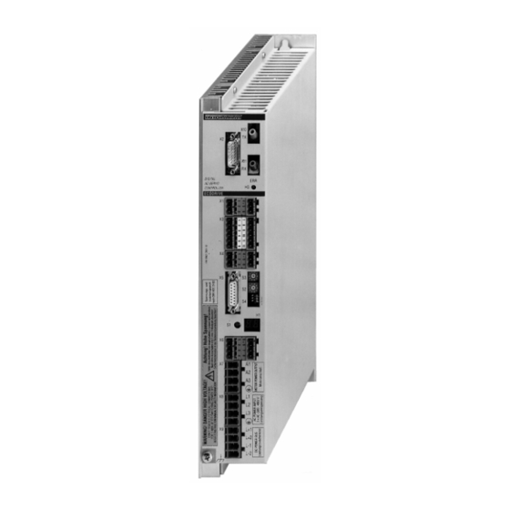
ECODRIVE DKC02.1 Drive Controller ECODRIVE DKC drive controllers An overview of the electrical connections Front view with supply terminals and overall connection diagram LWL connector for Connector for external SERCOS ring measuring system 15-pole D-Sub connector, socket DIGITAL Distortion-LED of AC-SERVO CONTROLLER SERCOS interface... - Page 32 ECODRIVE DKC drive controllers ECODRIVE DKC02.1 Drive Controller DKC02.1 Drive controller with SERCOS-interface RS 232- +24V Control voltage for DKC interface E-STOP Emergency stop RS485+ RS485+ RS 485- Zero point to control voltage interface RS485- RS485- Ready to operate Zero switch MKD- Motor Limit+...
-
Page 33: Electrical Connections
ECODRIVE DKC02.1 Drive Controller ECODRIVE DKC drive controllers Electrical connections The electrical connections are described below: • grouped according to numbers of the supply terminal strip (for exam- ple, X1, X2 etc.) • and then according to the functions. Serial interface X1 Maximum wire cross section which can be connected: 2.5 mm At present, the serial interface does not offer any functions for the user. -
Page 34: X3 Zero Switch, Sensor, Travel Limit Switch, Diagnostic Outputs
4-10 ECODRIVE DKC drive controllers ECODRIVE DKC02.1 Drive Controller X3 zero switch, sensor, travel limit switch, diagnostic outputs Maximum wire cross section which can be connected: 2.5 mm Zero switch, sensor, travel limit switch DC +24 V ±20% Control voltage connection +24V free E-STOP... -
Page 35: X4 24V Control Voltage Supply, E-Stop (Emergency Stop), Stand-By Operation
4-11 ECODRIVE DKC02.1 Drive Controller ECODRIVE DKC drive controllers X4 24V control voltage supply, E-stop (emergency stop), stand-by operation Maximum wire cross section which can be connected: 2.5 mm Voltage at X4/1: DC +24 V (± 20%) 24 control voltage supply Current consumption X4/1: 0.6 A An error message is displayed if there is a 20% drop in the 24 V. - Page 36 4-12 ECODRIVE DKC drive controllers ECODRIVE DKC02.1 Drive Controller Control unit Ready to operate control (DC 24 V) Energency- Stop- limit switch Emergency-stop etc. control SERCOS-master-modul Input X4 / 3 SERCOS interface-modul Drive controller DKC02.1-***-*-** FP5104F5.fh5 Fig. 4-17: Function E-stop For the precise mode of operation, please refer to the function description of the DKC02 (see page 3 of the supplementary documentation).
-
Page 37: X5 Connection For Motor Feedback
4-13 ECODRIVE DKC02.1 Drive Controller ECODRIVE DKC drive controllers X5 connection for motor feedback Maximum wire cross section which can be connected: 0.5 mm INDRAMAT feedback cables are preferred for the connection. Maximum cable length: 75 m Feed back cable No warranty! Use of non-INDRAMAT cables voids the warranty for the entire drive system. -
Page 38: X8 Power Connection
4-14 ECODRIVE DKC drive controllers ECODRIVE DKC02.1 Drive Controller X8 power connection Maximum wire cross section that can be connected: 4 mm Line input voltage: 3 x AC 380 ... 480 V (± 10%), 50 ... 60 Hz X9 DC bus connection Maximum wire cross section that can be connnected: 4 mm DC bus connection for connecting: an auxiliary bleeder module BZM01.1... -
Page 39: Switches
4-15 ECODRIVE DKC02.1 Drive Controller ECODRIVE DKC drive controllers Switches Switches S2, S3 The SERCOS address of the drive is determined by two decade switches. Switches S2, S3 The address can be a number ranging from 1 to 99. SERCOS address Example: switch position S3 = 9 (decadic value) switch position S2 = 1 (digit value) - Page 40 4-16 ECODRIVE DKC drive controllers ECODRIVE DKC02.1 Drive Controller ECODRIVE Switch for transmission power settings Switch for data rate settings FP5106F5.fh5 Fig. 4-20: Position of the switch for data rate and transmitter power demonstrat- ing how to switch it ON and OFF. The data rate is set with the switch S4/1.
-
Page 41: Bzm Auxiliary Bleeder Module
ECODRIVE DKC02.1 Drive Controller BZM auxiliary bleeder module BZM auxiliary bleeder module Dimensioning the components relevant for regeneration For each application, it is necessary to check whether the • continuous regenerative power • peak regenerative power • regenerative energy available from the application can be sufficiently absorbed by the bleeder (brake resistance). - Page 42 BZM auxiliary bleeder module ECODRIVE DKC02.1 Drive Controller 1 DKC + 1 BZM 1. Continuous regenerative power ≤ BD, DKC BD,BZM ∑ ∑ rot + * 1000 ⋅ π Last ⋅ ⋅ ⋅ Nutz ⋅...
- Page 43 ECODRIVE DKC02.1 Drive Controller BZM auxiliary bleeder module up to 6 DKCs 1. Continuous regenerative power ∑ ∑ ≤ 0 8 , BD,DKC ∑ ∑ rot + * 1000 ⋅ π Last ⋅ ⋅ ⋅ ...
- Page 44 BZM auxiliary bleeder module ECODRIVE DKC02.1 Drive Controller up to 6 DKCs + 1 BZM 1. Continuous regenerative power ∑ ∑ ∑ ≤ 0 8 , BD, DK C BD, B ZM ∑ ∑ rot + *1000 ⋅ π...
-
Page 45: Dimensional Data And Installation Dimensions
ECODRIVE DKC02.1 Drive Controller BZM auxiliary bleeder module Dimensional data and installation dimensions Clearance to adjacent units 32,5 min. 80 mm DIGITAL AC-SERVO BLEEDER ECODRIVE RESET min. 80 mm MB0200D4.fh5 Fig. 5-4: Dimensions of the auxiliary bleeding module BZM01.1 The BZM is delivered with screw-down push-in terminals. DOK-ECODRV-DKC02.1****-PRJ2-EN-P LSA Control S.L. -
Page 46: Technical Data
BZM auxiliary bleeder module ECODRIVE DKC02.1 Drive Controller Technical data Symbol Unit Value Designation Continuous bleeder output BD,BZM Peak bleeder output BM,BZM (perm. load cycle on for 1s, off for 40s) Maximum feedback energy MAX,BZM Control voltage DC 24 V ±20% N,BZM Current consumption of the N,BZM... -
Page 47: Electrical Connection
ECODRIVE DKC02.1 Drive Controller BZM auxiliary bleeder module Electrical connection BZM01.1 DKC**.*-040-7-FW +24 V Control voltage free connection free DC 24 V ± 20% Ready to operate max. DC 24 V/1 A Diameter of protective conductor connection must correspond to selection table 11-1 (Fusing) DC bus... - Page 48 BZM auxiliary bleeder module ECODRIVE DKC02.1 Drive Controller Notes DOK-ECODRV-DKC02.1****-PRJ2-EN-P LSA Control S.L. www.lsa-control.com comercial@lsa-control.com (+34) 960 62 43 01...
-
Page 49: Czm Auxiliary Capacitance Module
ECODRIVE DKC02.1 Drive Controller CZM auxiliary capacitance module CZM auxiliary capacitance module Dimensioning When braking the drive, the rotary energy available in the mechanics is released as regenerative energy in the DC bus of the DKC. It can be • released in the form of heat via the bleeder module or auxiliary bleeder integrated into the DKC - or - •... - Page 50 CZM auxiliary capacitance module ECODRIVE DKC02.1 Drive Controller DKC01.-40-7 with AC motor MKD 071 B with the following data: Application example Designation Value Rotor inertia of the MKD 071 B = 0.00087 kgm² Maximum effective motor speed = 3200 min-1 NUTZ Load inertia of the application = 0.00261 kgm²...
-
Page 51: Dimensional Data And Installation Dimensions
ECODRIVE DKC02.1 Drive Controller CZM auxiliary capacitance module Dimensional data and installation dimensions Clearance to adjacent units 32,5 min. 80 mm DIGITAL AC-SERVO CAPACITOR ECODRIVE min. 80 mm MB0203D4.fh5 Fig. 6-6: Dimensions for the auxiliary capacitance modules CZM01.1 DOK-ECODRV-DKC02.1****-PRJ2-EN-P LSA Control S.L. www.lsa-control.com comercial@lsa-control.com (+34) 960 62 43 01... -
Page 52: Front View
CZM auxiliary capacitance module ECODRIVE DKC02.1 Drive Controller Front view DIGITAL AC-SERVO CAPACITOR ECODRIVE X9 Plug-in screw terminal 0.2 to 4 mm², AWG 24-10, Protective conductor connection DC bus connection F03DCC1P.fh5 Fig. 6-7: Front view of the auxiliary capacitance module CZM01.1 Electrical connection CZM01.1 DKC**.*-040-7-FW... -
Page 53: Type Code And Rating Plate
ECODRIVE DKC02.1 Drive Controller CZM auxiliary capacitance module Type code and rating plate CZM 01.1 - 01 - 07 Example: Type code fields: Auciliary capacitance module Series Version Rated capacity 1,0 mF DC bus nominal voltage 700 V TL0204D4.fh5 Fig. 6-9: Type code Type of machine Production week CZM01.1-01-07... - Page 54 CZM auxiliary capacitance module ECODRIVE DKC02.1 Drive Controller Notes DOK-ECODRV-DKC02.1****-PRJ2-EN-P LSA Control S.L. www.lsa-control.com comercial@lsa-control.com (+34) 960 62 43 01...
-
Page 55: Dc24V Power Supplies Ntm
ECODRIVE DKC02.1 Drive Controller DC24V power supplies NTM DC24V power supplies NTM Application recommendations If there is no external DC24V control voltage available, then INDRAMAT recommends the use of NTM power supply units. • The power supplies contain an overvoltage safety switch with auto- Features matic shutdown. -
Page 56: Dimensional Data And Installation Dimensions
DC24V power supplies NTM ECODRIVE DKC02.1 Drive Controller Dimensional data and installation dimensions Power supply unit NTM01.1-024-.. Table of dimensions A Connecting block INDRAMAT B L-rails DIN 50 Type of power unit 168.7 NTM01.1-024-002 C > 20 mm 197.7 NTM01.1-024-004 cooling clearance NTM01.1-024-006 207.7... -
Page 57: Electrical Connection
ECODRIVE DKC02.1 Drive Controller DC24V power supplies NTM Potentiometer for fine LED green = output adjustments of output voltage applied voltage S+ sensor input DC 24 V V+ Output voltage Zero point V- S- sensor input Protective ground Input voltage Input setting voltage... -
Page 58: Type Code
DC24V power supplies NTM ECODRIVE DKC02.1 Drive Controller Type code NTM 01.1 - 024 - 02 Example: Type codes Power supply module Series Version Output nominal voltage DC 24 V Output nominal current 2,1 A 4,2 A 6,3 A TL0205D4.fh5 Fig. -
Page 59: Line Filter Nfd/ Nfe
ECODRIVE DKC02.1 Drive Controller Line filter NFD/ NFE Line filter NFD/ NFE Selection The filters listed here are designed for the DKC drive controller power connection. Please see Chap. 8.4, for information on the line filter for interference suppression on the DC24V NTM power supply. Technical data for line filters Max. -
Page 60: Dimensional Data And Installation Dimensions
Line filter NFD/ NFE ECODRIVE DKC02.1 Drive Controller Dimensional data and installation dimensions NFD02.1-480-008 0,75 NFD02.1-480-016 NFD02.1-480-030 NFD02.1-480-055 NFD02.1-480 Dimen- sion Tolerance ...-016 ...-030 ...-055 ±1 ±1.5 142±0.8 150±1 185±1 ±0.6 ±1 275±0.8 ±0.5 ±0.3 ±0.2 ±15 ±0.2 1+0.1 1+0.1 ±1 MB5105D4.fh5 Fig. -
Page 61: Electrical Connection
ECODRIVE DKC02.1 Drive Controller Line filter NFD/ NFE The mounting plate or the control cabinet housing to which the DKC is Notes on assembly mounted are the preferred locations for assembly. Live parts (greater than 50 V)! Electric shock on contact! ⇒... -
Page 62: Line Filters For Dc24V Ntm Power Supplies
Line filter NFD/ NFE ECODRIVE DKC02.1 Drive Controller Line filters for DC24V NTM power supplies When using the NTM power supply, use the NFE01.1-250-006 line filter for interference suppression. 43.2 MB0206D4.fh5 Fig. 8-5: Dimension drawing: line filter NFE01.1-250-006 Mains side Machine side NFE01.1-250-006 AP0228D4.fh5... -
Page 63: Dst / Dlt Transformers
ECODRIVE DKC02.1 Drive Controller DST / DLT transformers DST / DLT transformers Selection Transformers are only needed if the systems voltage exceeds the per- mitted rated voltage of the DKC. For grounded power supply lines, the line voltage is matched to the rated Grounded power supply lines voltage of the units using autotransformers which are suitable for one specific output voltage range (see Fig. - Page 64 DST / DLT transformers ECODRIVE DKC02.1 Drive Controller i = 0.52 i = 1.08 i = 1.26 i = 1.50 AC(200...240)V AC(480...500)V DST**/*/240-460 DST**/*/500-460 AC(480...580)V DST**/*/580-460 AC(570...690)V DST**/*/690-460 DG0203D4.fh5 Input voltage in V of the transformer Fig. 9-1: Classification of three-phase autotransformers into rating groups DOK-ECODRV-DKC02.1****-PRJ2-EN-P LSA Control S.L.
- Page 65 ECODRIVE DKC02.1 Drive Controller DST / DLT transformers DST autotransformer with secondary or output voltage AC (380 to 460) V Standing version for mounting with base: DST..,../S H Æ Rating plate (example) Block diagram GmbH D 97816 Lohr a. M. Type DST 20/S/580 - 480 1993...
-
Page 66: Electrical Connection Of The Dkc Via Transformer
DST / DLT transformers ECODRIVE DKC02.1 Drive Controller Electrical connection of the DKC via transformer Power connection at X8: 3xAC380...480 V with DKC**.*-040-7- Mains filter Power connection for further 3 x AC DKCs 50...60 Hz Protective conductor connection ≥ 10mm (EN50178) AP0249D4.fh5 Fig. -
Page 67: Planning The Control Cabinet
10-1 ECODRIVE DKC02.1 Drive Controller Planning the control cabinet Planning the control cabinet 10.1 Notes on installing the control cabinet When planning the control cabinet, it is necessary to take the technical data of the drive components into account. Power dissipation Power dissipation is determined by the current load and the continuous regenerative power. -
Page 68: 10.2 Using Heat-Exchange Units In The Control Cabinets
10-2 Planning the control cabinet ECODRIVE DKC02.1 Drive Controller 10.2 Using heat-exchange units in the control cabinets Improperly installed and operated heat-exchange units are a risk to the drive components installed in the control cabinet due to the condensation and condensed water which these may cause! Humid air enters the cabinet and, as it cools, condenses onto the installed Risk of condensation drive components. - Page 69 10-3 ECODRIVE DKC02.1 Drive Controller Planning the control cabinet correct incorrect Cooling system Cooling system warm cold warm cold Air duct electronic electronic equipment equipment Cabinet Cabinet EB0200D4.fh5 Fig. 10-2: Arranging the heat-exchange unit on the top of the control cabinet correct incorrect Cabinet...
-
Page 70: 10.3 Interference Suppression Measures And Emc
10-4 Planning the control cabinet ECODRIVE DKC02.1 Drive Controller 10.3 Interference suppression measures and EMC The assembly and installations regulations laid out in the project planning document "EMC for Drive and Control systems" must be adhered to in or- der to fulfill the legal EMC requirements. DOK-ECODRV-DKC02.1****-PRJ2-EN-P LSA Control S.L. -
Page 71: Power Connection
11-1 ECODRIVE DKC02.1 Drive Controller Power connection Power connection 11.1 Direct power connection The drives controller DKC**.1-040-7-FW can be connected directly to grounded three-phase current lines with AC 380...480 V, ±10 %. Only a fuse protector Q1, a line contactor K1, and normally a line filter are re- quired in the power input line. -
Page 72: 11.2 Line Contactor/Fuse Protector
11-2 Power connection ECODRIVE DKC02.1 Drive Controller 11.2 Line contactor/fuse protector A selection table (Fig. 11-5) is available to facilitate the selection of a suit- able line contactor and fuse protector for the power connection. Calculating the phase current at the power connection To be able to select a suitable line contactor and a suitable power con- nection fuse protection, the phase current I at the power connection must... -
Page 73: Selecting The Fuse Protector Q1 And Line Contactor K1
11-3 ECODRIVE DKC02.1 Drive Controller Power connection Selecting the fuse protector Q1 and line contactor K1 The fuse protector must be rated 1.5 times higher than the actual current Fuse protector Q1 at the power connection I Fuse protection can be implemented using: •... -
Page 74: 11.3 Control Circuit To The Power Connection
11-4 Power connection ECODRIVE DKC02.1 Drive Controller 11.3 Control circuit to the power connection The control circuit recommended by INDRAMAT represents the function principle. The choice of the control and its efficiency depends on the range of func- tions and the course of efficiency of the entire system or machine. Therefore, it is the manufacturer’s responsibility to make this choice. - Page 75 11-5 ECODRIVE DKC02.1 Drive Controller Power connection External control +DC 24 V Limit switch E-stop Power off Control error message X4/3 Power on E-STOP DKC ready to operate X4/6 Mains contactor Integrate Bb contact of additional DKCs and BZM into the series connection E-Stop for additional DKCs on same mains contactor Switching capacity DC 24V/1A AP5110D4.fh5...
-
Page 76: 11.4 Reaction Of The Drive To Malfunctions
11-6 Power connection ECODRIVE DKC02.1 Drive Controller 11.4 Reaction of the drive to malfunctions Power failure If during a power failure the 24V control voltage for the drive controller is buffered, the motor can be brought to a standstill by braking. If during a power failure there is no 24 V control voltage, the motor be- comes torque-free and coasts to a standstill. -
Page 77: Fatal Errors
11-7 ECODRIVE DKC02.1 Drive Controller Power connection Fatal errors If fatal errors occur in the drive system, the motor can no longer be stopped by braking. The motor becomes torque-free and coasts to a standstill. An example of a fatal error is when the bridge fuse blows. (see function description). - Page 78 11-8 Power connection ECODRIVE DKC02.1 Drive Controller Notes DOK-ECODRV-DKC02.1****-PRJ2-EN-P LSA Control S.L. www.lsa-control.com comercial@lsa-control.com (+34) 960 62 43 01...
-
Page 79: Preparing For Startup
12-1 ECODRIVE DKC02.1 Drive Controller Preparing for Startup Preparing for Startup Required equipment The digital drives are generally started up via the terminal of a SERCOS SERCOS PC interface interface compatible control It this is not possible, operation can be started via the INDRAMAT SERCOS PC interface. - Page 80 12-2 Preparing for Startup ECODRIVE DKC02.1 Drive Controller hand-held unit max. cable length 10 SERCOS PC interface supply terminals for - Emergency-stop - 24V-power for IBM-compatible AT with hand-held terminal - a free 8Bit-expansion slot - free system memory ≥640 KRAM - a floppy disk drive SERCOS interface - an EGA/VGA graphic board...
-
Page 81: Condition Of The Drive Components On Delivery
13-1 ECODRIVE DKC02.1 Drive Controller Condition of the drive components on delivery Condition of the drive components on delivery Packaging ECODRIVE components are delivered in separate packaging units. Packaging units Accessories are fastened to the unit. INDRAMAT will take packaging materials back. The customer is liable for Packaging materials return transport costs. - Page 82 13-2 Condition of the drive components on delivery ECODRIVE DKC02.1 Drive Controller Notes DOK-ECODRV-DKC02.1****-PRJ2-EN-P LSA Control S.L. www.lsa-control.com comercial@lsa-control.com (+34) 960 62 43 01...
-
Page 83: Index
14-1 ECODRIVE DKC02.1 Drive Controller Index Index ECODRIVE 10-4 E-stop 11-4 E-stop connections 4-14 Accompanying documents 13-1 Ambient temperature Autotransformer Filter Auxiliary bleeder module Firmware Auxiliary capacitance module Firmware type code Front view BZM01.1 CZM01.1 DKC02.1 NTM01.1 7-2, 7-3 Fuse protection Q2 Cabel length 4-15 Fuse protector Q1... - Page 84 14-2 Index ECODRIVE DKC02.1 Drive Controller Power supplies Type code BZM01.1 CZM01.1 DKC02.1 Rating plate Line filter BZM01.1 CZM01.1 Type code for transformers DKC02.1 Ready for operation 4-14, 11-4 Ungrounded power lines Regenerated energy Resources 12-1 Rotary energy Zero switch 4-12 Selecting the components Sensor...
- Page 85 ECODRIVE DKC02.1 Drive Controller Directory of customer service locations Directory of customer service locations Germany Sales Region Central Sales Region East Sales Region West Sales Region North INDRAMAT GmbH INDRAMAT GmbH INDRAMAT GmbH INDRAMAT GmbH D-97816 Lohr am Main D-09120 Chemnitz D-40849 Ratingen D-22085 Hamburg Bgm.-Dr.-Nebel-Str.
- Page 86 Directory of customer service locations ECODRIVE DKC02.1 Drive Controller Other international locations Argentina Argentina Australia Brazil Mannesmann Rexroth S.A.I.C. Nakase Australian Industrial Machenery Mannesmann Rexroth Automação Division INDRAMAT Asesoramiento Tecnico Services Pty. Ltd. Ltda. Acassusso 48 41/7 Diaz Velez 2929 Unit 3/45 Horne ST Divisão INDRAMAT 1605 Munro (Buenos Aires)
- Page 87 ECODRIVE DKC02.1 Drive Controller Directory of customer service locations Notes DOK-ECODRV-DKC02.1****-PRJ2-EN-P LSA Control S.L. www.lsa-control.com comercial@lsa-control.com (+34) 960 62 43 01...
- Page 88 Indramat LSA Control S.L. www.lsa-control.com comercial@lsa-control.com (+34) 960 62 43 01...
Need help?
Do you have a question about the Rexroth Indramat ECODRIVE DKC02.1 Series and is the answer not in the manual?
Questions and answers