Siemens FDCL221 Technical Manual
Line separator
Hide thumbs
Also See for FDCL221:
- Technical manual (30 pages) ,
- Installation (4 pages) ,
- Manual (6 pages)

Related Manuals for Siemens FDCL221


Summary of Contents for Siemens FDCL221
- Page 1 FDCL221 Line separator Technical Manual 007063_h_en_-- Smart Infrastructure 2019-07-04...
- Page 2 All rights created by patent grant or registration of a utility model or design patent are reserved. Issued by: Siemens Switzerland Ltd. Smart Infrastructure Global Headquarters Theilerstrasse 1a CH-6300 Zug Tel. +41 58 724-2424 www.siemens.com/buildingtechnologies Edition: 2019-07-04 Document ID: 007063_h_en_-- © Siemens Switzerland Ltd, 2004 2 | 32 007063_h_en_--...
-
Page 3: Table Of Contents
Table of contents About this document ................5 Applicable documents ................. 7 Download center ..................8 Technical terms ..................8 Revision history ..................9 Safety ....................10 Safety instructions ..................10 Safety regulations for the method of operation ...........11 Standards and directives complied with............13 Release Notes ...................13 Structure and function ................. - Page 4 4 | 32 007063_h_en_--...
-
Page 5: About This Document
This document contains all information on the line separator FDCL221. Consistent compliance with the instructions guarantees correct and safe use. Intended use The line separator FDCL221 may only be used for short-circuit and open line monitoring in one of the following fire detection systems: ●... - Page 6 About this document Applicable documents Target groups The information in this document is intended for the following target groups: Target group Activity Qualification Product Manager ● Is responsible for information ● Has obtained suitable specialist passing between the manufacturer training for the function and for the and regional company.
-
Page 7: Applicable Documents
The 'i' symbol identifies supplementary information and tips for an easier way of working. 1.1 Applicable documents Document ID Title 007065 Data sheet Line separator FDCL221 008025 Installation Line separator FDCL221 008331 List of compatibility (for 'Sinteso™' product line) 008843... -
Page 8: Download Center
You can download various types of documents, such as data sheets, installation instructions, and license texts via the following Internet address: https://siemens.com/bt/download Enter the document ID in the search field. You will also find information about search variants and links to mobile applications (apps) for various systems on the home page. -
Page 9: Revision History
About this document Revision history 1.4 Revision history The reference document's version applies to all languages into which the reference document is translated. The first edition of a language version or a country variant may, for example, be version 'd' instead of 'a' if the reference document is already this version. The table below shows this document's revision history: Version Edition date... -
Page 10: Safety
Safety Safety instructions 2 Safety 2.1 Safety instructions The safety notices must be observed in order to protect people and property. The safety notices in this document contain the following elements: ● Symbol for danger ● Signal word ● Nature and origin of the danger ●... -
Page 11: Safety Regulations For The Method Of Operation
2.2 Safety regulations for the method of operation National standards, regulations and legislation Siemens products are developed and produced in compliance with the relevant European and international safety standards. Should additional national or local safety standards or legislation concerning the planning, mounting, installation,... - Page 12 Modifications to the system design and the products Modifications to the system and to individual products may lead to faults, malfunctioning and safety risks. Written confirmation must be obtained from Siemens and the corresponding safety bodies for modifications or additions. Modules and spare parts ●...
-
Page 13: Standards And Directives Complied With
Personal injury or damage to property caused by poor maintenance or lack of maintenance 2.3 Standards and directives complied with A list of the standards and directives complied with is available from your Siemens contact. 2.4 Release Notes Limitations to the configuration or use of devices in a fire detection installation with a particular firmware version are possible. -
Page 14: Structure And Function
3 Structure and function 3.1 Overview Figure 1: Line separator FDCL221 The line separator FDCL221 is an electronic switch which is mounted on a FDnet/C-NET detector line. The line separator detects short-circuits and open lines on the detector line and disconnects the negative conductor in the event of a short-circuit. -
Page 15: Details For Ordering
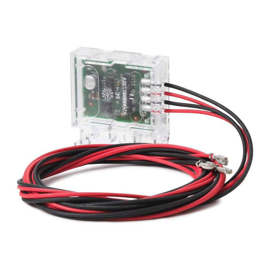
Type Order number Designation FDCL221 A5Q00004011 Line separator 3.2 Setup Figure 2: View of FDCL221 with open housing 1 Housing cover 4 PCB 2 Yellow LED 5 Stranded cable with 2.8 x 0.8 mm flat connector sleeve 3 Back box 3.2.1 Indication elements... -
Page 16: Function
Structure and function Function 3.3 Function The line separator FDCL221 is an electronic switch which is mounted on a FDnet/C-NET detector line. Station FDCL221 FDCL221-M Figure 3: Use of a line separator FDCL221 on a FDnet/C-NET detector line The line separator detects short-circuits and open lines on the detector line and disconnects the negative conductor in the event of a short-circuit. -
Page 17: Accessories
● Compatible with: – Various input/output modules – Line separator FDCL221 – Mounting foot FDCM291 – Line adapter (Ex) FDCL221-Ex – Sounder module FCA2005-A1 – Fiber network module FN2006/FN2007 ● Order number (length 122 mm): BPZ:5644780001 ● Order number (length 288 mm): BPZ:5644230001 3.4.2 Connection terminal DBZ1190-AB... -
Page 18: Planning
Station FDCL221 FDCL221-M Figure 4: Line separator FDCL221 between two sub-stubs If several sub-stub lines are to be activated on one FDnet/C-NET loop, failure of large numbers of devices must be prevented in the event of a line short-circuit. In this regard the national regulations must be observed. - Page 19 The following figures show the common variants of a modernized detector line on which the FDnet/C-NET devices (T) are installed with integrated line separation function. The outgoing stub lines A to D are connected to the FDCL221 line separators via terminal blocks or micro terminals (X).
- Page 20 Planning Accessories Figure 6: Housing FDCL221 line separator in the control panel 1 Control panel C Sub-stub C 2 FDnet/C-NET loop D Sub-stub D 3 Line separator FDCL221 T FDnet/C-NET device A Sub-stub A X Terminal blocks or micro terminals...
-
Page 21: Compatibility
Planning Compatibility 4.1 Compatibility Compatible with control panels that support the FDnet/C-NET detector line. Detector line FC20xx FC72x SIGMASYS AlgoRex FC360 FDnet – – C-NET – – – With suitable line card X = compatible – = not compatible You will find detailed information in the 'List of compatibility'. 4.2 Fields of application The line separator is required in a FDnet/C-NET, where several sub-stub lines converge at one point. -
Page 22: Mounting / Installation
5 Mounting / Installation 5.1 Assembly The line separator may be fitted in any position. Ensure that the line separator LED is visible after mounting. You can fit the FDCL221 line separator in various ways: ● Directly on a U-rail TS35 ●... -
Page 23: Installation
Only connect one wire per terminal. This is the only way to ensure the connection is failure-free for the entire service life of the device. The connection diagram shows the electrical connection for the FDCL221 line separator in the FDnet/C-NET using terminal blocks or micro terminals. -
Page 24: Wiring
Mounting / Installation Installation 5.2.1 Wiring w Always insert a line separator before a sub-stub line. 1. Connect the line separator to the FDnet/C-NET. The pigtails are provided with pressed-on 2.8 x 0.8 mm flat connector sleeves in the factory. Cut off the flat connector sleeves if you don't need them for the connection. -
Page 25: Shielded Cable
Mounting / Installation Installation 5.2.2 Shielded cable Shielded cables must be earthed in stars at one point (e.g. on the control panel). Cable shieldings must be linked with one another using an insulated micro terminal or connection terminal. The shielding must not touch any extrinsic earthing potentials or metal parts in the device. -
Page 26: Commissioning
Commissioning 6 Commissioning The devices are commissioned via the control panel. The exact procedure is described in the control panel documentation. Conduct a performance check once commissioning is complete. 26 | 32 007063_h_en_--... -
Page 27: Maintenance And Troubleshooting
Maintenance and troubleshooting 7 Maintenance and troubleshooting The line separator module is maintenance-free. It monitors itself and has to be replaced if damaged. 007063_h_en_-- 27 | 32... -
Page 28: Specifications
Specifications Technical data 8 Specifications 8.1 Technical data You will find information on approvals, CE marking, and the relevant EU directives for this device (these devices) in the following document(s); see 'Applicable documents' chapter: ● Document 007065 Detector line Operating voltage DC 12…33 V Operating current (quiescent) 250 µA... - Page 29 Specifications Technical data Ambient conditions Operating temperature -25…+70 °C Operating temperature tested according to -10…+55 °C EN 54-17 Storage temperature -30…+80 °C Air humidity (non-condensing) ≤95 % rel. Protection category (IEC 60529) IP44 Mechanical data Dimensions (L x W x H) 47.5 x 44 x 10 mm Weight 0.038 kg...
-
Page 30: Dimensions
Specifications Dimensions 8.2 Dimensions Figure 11: Dimensions of FDCL221 line separator 1 Pigtail 0.5 mm , length = 500 mm, with 2.8 x 0.8 mm flat connector sleeve pressed on in the factory 8.3 Environmental compatibility and disposal This equipment is manufactured using materials and procedures which comply with current environmental protection standards as best as possible. -
Page 31: Index
Index Index Chemicals ............21 Moisture ............21 Application area Temperature ........... 21 Ambient conditions.......... 21 Installation site Approvals ............28 Control panel ..........20 Attachment Intermediate distributor ........19 Cable tie ............15 Intended use ............. 5 Screw ............. 15 Intermediate distributor U-rail............... - Page 32 © Siemens Switzerland Ltd, 2004 Issued by Siemens Switzerland Ltd Technical specifications and availability subject to change without notice. Smart Infrastructure Global Headquarters Theilerstrasse 1a CH-6300 Zug +41 58 724 2424 www.siemens.com/buildingtechnologies 007063_h_en_--...
Need help?
Do you have a question about the FDCL221 and is the answer not in the manual?
Questions and answers