Advertisement
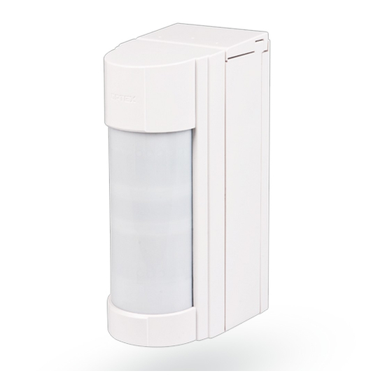
The JA-159P wireless outdoor PIR detector
This detector is a component of the JABLOTRON 100 system.
The JA-159P
wireless
outdoor
to detect human body movement in an outdoor environment.
It is the VXI-RAM detector produced by Optex with a transmitter
JA-150TX-VXI produced by JABLOTRON ALARMS. The optical part
of the detector has 2 PIR sensors (dual zone detection) and a high
immunity to false alarms and the detection of small animals. The detector
includes an Anti-masking function – protection against covering the view
and it also has two tampers (front and back) built in. They immediately
report opening the detector or attempting tampering. The detector should
be installed by a trained technician with a valid certificate issued
by an authorised distributor.
Installation
Conditions:
1. The detector has to be installed onto a vertical wall (in a position
where its bottom surface is parallel to the watched zone).
2.
The detector should be installed 0.8 – 1.2 m above the ground.
3.
The best movement detection is provided when the detection beams
intersect.
4. No other moving objects (bushes, trees, high grass, air-conditioners,
etc.) should be situated in the field of view of the detector.
5. Avoid direct effects by strong sources of light (sun reflections, etc.).
Procedure:
1. Unscrew the locking screw on the bottom of the upper cover
of the detector (1) and remove the detection part's cover (1).
2. Unscrew the 2 screws which hold the detector´s main board (2)
and pull it out by tilting as you pull it out. There is also a radio
transmitter glued onto the rear side of the detector´s PCB.
3. Remove the rear box cap (5) by pulling it up.
4. Unscrew the 2 screws which link the rear cover (3) with
the mounting plate (4).
5. The detector can be mounted onto a level mounting place
by the 2 screws through the mounting plate (4). Or it can be
mounted on a pole by metal ties (not supplied).
Warning: Do not touch the detector sensing face
If it does happen, it´s necessary to clean it up by
a cotton swab dipped in alcohol.
2
1
Fig. 1.: 1 – front cover, 2 – detector main board,
3 – rear cover, 4 – mounting plate, 5 – rear cover cap
The JA-159P wireless outdoor PIR detector
intruder
detector
is
designed
during handling
5
4
3
Fig. 2.: Detector installation. Standard wall installation and fixing by ties.
Enrolling the detector to the system
The signal transmitter for wireless communication is located under
the main board part of the detector. The batteries are inserted into
the battery holder placed on the transmitter PCB. Use two CR123A
(3 V, 1.4 Ah) lithium batteries from the same manufacturer.
The correct position of the batteries is indicated on the battery holder.
Enrolment procedure to the system:
a.
Go to the F-Link software, select
the required position in the Devices
window and launch the enrollment mode
by clicking on the Enroll option.
b. Insert the batteries (mind the correct
polarity). When the first battery has been
inserted
into
the
an enrollment signal is transmitted
to the control panel and the detector
is enrolled to the selected position.
c.
Assemble the detector in opposite order
to which it was disassembled.
Fig. 3 – Transmitter JA-150TX-VXI: 1 – terminals for connection to the
detector, 2 – red activation indication LED; 3 – yellow Antimasking
activation and low battery indication LED; 4 – battery holder;
5 – external antenna connector; 6 – production code
Notes:
-
There must be a JA-11xR radio module installed in the control
panel.
-
The detector can also be enrolled into the system by entering its
production code (9) in the F-Link software. You can find the
production code on the sticker, glued onto the PCB. All numbers
under the bar code shall be entered (1400-00-0000-0001).
-
If needed the transmitter can be equipped with an AN-868
(3 PIN) external antenna connected to the connector (5).
Normal operating mode
The detector sends a radio signal about activation when
it is triggered. In the case of tampering with the detector or tearing
the detector off its position the detector sends a tamper signal.
Every 9 minutes a status report is sent to the control panel.
Checking and replacing the batteries
The
detector
checks
Nearly drained battery is reported by continuous flashing of yellow
signalling LED on the detector (1 flash per sec) and at the same time
low battery status is reported to the control panel. The detector
remains fully functional. The battery should be changed as soon
as possible.
The control panel must be in service mode before battery
changing
(see
the
Tamper contact must be pressed several times after opening
the cover and removing the battery to discharge capacitors.
Use only lithium batteries CR123A (3 V, 1.4 Ah) from the same
manufacturer. Always replace all batteries simultaneously.
Setting up the optical part
The optical part of the detector includes 2 PIR sensors with AND
logic. They detect movement in two planes. The detecting angle
of the lower PIR sensor can be adjusted. The alarm signal
is triggered if only both detecting planes are triggered at the same
time. By shifting the lens set up the tilt of the lower detecting plane
according to the following picture and table.
1 / 2
battery
holder
the
battery
status
control
panel
installation
of the detector
automatically.
manual).
MMY51809
Advertisement
Table of Contents

Subscribe to Our Youtube Channel
Related Manuals for jablotron JA-159P


Summary of Contents for jablotron JA-159P
- Page 1 The JA-159P wireless outdoor PIR detector This detector is a component of the JABLOTRON 100 system. The JA-159P wireless outdoor intruder detector designed to detect human body movement in an outdoor environment. It is the VXI-RAM detector produced by Optex with a transmitter JA-150TX-VXI produced by JABLOTRON ALARMS.
- Page 2 – checking the coverage. The detector always sends information to the control panel. For normal detector operation we recommend JABLOTRON ALARMS a.s. hereby declares that the JA-159P the LED to be turned off in order to save the battery. composed of Optex detector VXI-RAM-NB and radio module JA-150TX-VXI is in a compliance with the relevant Union The power save mode can be set up by DIP switch no.
Need help?
Do you have a question about the JA-159P and is the answer not in the manual?
Questions and answers