Table of Contents
Advertisement
Quick Links
Download this manual
See also:
User Manual
USER GUIDE
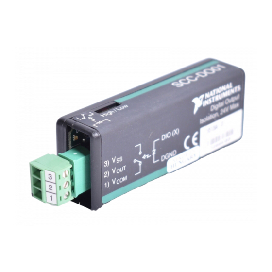
SCC-DO01 Isolated Digital Output
Module
Conventions
»
bold
italic
The SCC-DO01 is a single-channel, optically isolated digital output
module. The output circuitry consists of a photomos relay and a load
resistor. You can use the SCC-DO01 with a 5–24 VDC external voltage
supply to switch external devices such as transistors and solid-state relays.
The following conventions are used in this guide:
The » symbol leads you through nested menu items and dialog box options
to a final action. The sequence File»Page Setup»Options directs you to
pull down the File menu, select the Page Setup item, and select Options
from the last dialog box.
This icon denotes a caution, which advises you of precautions to take to
avoid injury, data loss, or a system crash. When this symbol is marked on
the product, see the Read Me First: Safety and Radio-Frequency
Interference document, shipped with the product, for precautions to take.
This icon denotes a note, which alerts you to important information.
When symbol is marked on a product, it denotes a warning advising you to
take precautions to avoid electrical shock.
When symbol is marked on a product, it denotes a component that may be
hot. Touching this component may result in bodily injury.
Bold text denotes items that you must select in software, such as menu
items and dialog box options. Bold text also denotes parameter names.
Italic text denotes variables, emphasis, a cross reference, or an introduction
to a key concept. This font also denotes text that is a placeholder for a word
or value that you must supply.
Advertisement
Table of Contents

Related Manuals for National Instruments SCC-DO01


Summary of Contents for National Instruments SCC-DO01
- Page 1 The SCC-DO01 is a single-channel, optically isolated digital output module. The output circuitry consists of a photomos relay and a load resistor. You can use the SCC-DO01 with a 5–24 VDC external voltage supply to switch external devices such as transistors and solid-state relays.
-
Page 2: What You Need To Get Started
SC-2345 refers to both the SC-2345 connector block and the SC-2345 with configurable connectors. SCC refers to any SCC Series signal-conditioning module. What You Need to Get Started To set up and use the SCC-DO01, you need the following items: ❑ SC-2345/2350 with one of the following: –... -
Page 3: Device Specific Information
Refer to the Read Me First: Safety and Radio-Frequency Interference document before removing equipment covers or connecting/disconnecting any signal wires. Plug the SCC-DO01 into any digital input/output (P0.) socket J(X+9), where X is 0 to 7, on the SC-2345. When you configure the SC-2345 according to the procedure in the SCC Quick Start Guide, the SC-2345 routes the output signal from digital line P0.(X) on the E Series DAQ... - Page 4 V terminals and a voltage supply connected to the V and V terminals. Connect Configuration 1 to the SCC-DO01 by completing the following steps: Remove all power from the signal lines. Strip 7 mm (0.27 in.) of insulation from the ends of the signal wires.
- Page 5 V terminals and a voltage supply connected to the V and V terminals. Connect Configuration 2 to the SCC-DO01 by completing the following steps: Remove all power from the signal lines. Strip 7 mm (0.27 in.) of insulation from the ends of the signal wires.
-
Page 6: Specifications
0.4 V High (I = 0 mA) Maximum continuous load current (I Configuration 1........86 mA Configuration 2........120 mA = 24 V) Minimum load resistance (at V ..........196 Ω LOAD1 ..........184 Ω LOAD2 SCC-DO01 Isolated Digital Output Module User Guide ni.com... - Page 7 Fall time ..........25 µs typ The switching characteristics (turn-on time, switching time, and turn-off time) of the optical isolator used on the board limit the data transfer rate. © National Instruments Corporation SCC-DO01 Isolated Digital Output Module User Guide...
-
Page 8: Power Requirement
Humidity ..........10 to 90% RH, noncondensing Maximum altitude........2,000 m Pollution Degree (indoor use only) ..2 Safety The SCC-DO01 meets the requirements of the following standards for safety and electrical equipment for measurement, control, and laboratory use: • IEC 61010-1, EN 61010-15 •... -
Page 9: Electromagnetic Compatibility
To obtain the DoC for this product, visit , search by model number or product line, and click the ni.com/hardref.nsf appropriate link in the Certification column. © National Instruments Corporation SCC-DO01 Isolated Digital Output Module User Guide... - Page 10 Figure 5 shows the I/O connector on the bottom of the SCC-DO01. 1 Pin 1 Pin 2 PWB Key Pin 19 5 Pin 20 Figure 5. SCC Module Bottom View Table 1 lists the signal connection corresponding to each pin. GND is the reference for the +5 V supply.
-
Page 11: Theory Of Operation
Theory of Operation Setting the Power-Up State of the SCC-DO01 The switch for setting the power-up state of the SCC-DO01 is on the top of the module. Switch it to High or Low depending on whether you want the output state to be high or low on power-up. The switch does not override the output state as determined by the E Series DAQ device. -
Page 12: Signal Isolation
, and V signals on each SCC-DO01 are isolated from other channels and from the SCC-DO01 internal power and ground signals. The isolation barrier protects the SCC-DO01 and other equipment from voltages up to +42 VDC. Common-mode voltages higher than +42 VDC can damage the SCC-DO01 and other equipment.
Need help?
Do you have a question about the SCC-DO01 and is the answer not in the manual?
Questions and answers