
Related Manuals for Stahl C-Lux 6109/1 Series


Summary of Contents for Stahl C-Lux 6109/1 Series
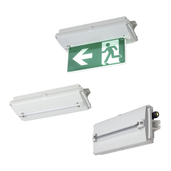
- Page 1 Operating instructions Additional languages r-stahl.com Compact Luminaire with LED Series C-Lux 6102/1, Series C-Lux 6109/1...
-
Page 2: Table Of Contents
Contents General Information ....................3 Manufacturer .......................3 About these operating instructions ..............3 Further documents ....................3 Conformity with standards and regulations ............4 Explanation of the symbols .................4 Symbols in these operating instructions .............4 Symbols on the device ..................4 Safety ........................5 Intended Use .......................5 Personnel qualification ..................5 Residual risks ......................6 Transport and storage ..................7... -
Page 3: General Information
General Information General Information Manufacturer R. STAHL Schaltgeräte GmbH R. STAHL (P) LTD., Plot No. - 5 Am Bahnhof 30 Malrosapuram Road, Sengundram Indl. Area 74638 Waldenburg Singaperumal Koil, Kancheepuram Dist., Germany Tamil Nadu – 603 204, INDIA Phone: +49 7942 943-0... -
Page 4: Conformity With Standards And Regulations
Explanation of the symbols Conformity with standards and regulations • Certificates and EU Declaration of Conformity: r-stahl.com. • The device has IECEx approval. See IECEx homepage: http://iecex.iec.ch/ to view the certificate. • Further national certificates can be downloaded via the following link: https://r-stahl.com/en/global/support/downloads/. -
Page 5: Safety
Specialists who perform these tasks must have a level of knowledge that meets applicable national standards and regulations. Additional knowledge is required for tasks in hazardous areas! R. STAHL recommends having a level of knowledge equal to that described in the following standards: •... -
Page 6: En 3.3 Residual Risks
Transport the device only in its original packaging or in equivalent packaging. Check the packaging and the device for damage. Report any damage to R. STAHL immediately. Do not commission a damaged device. Store the device in its original packaging in a dry place (with no condensation), and make sure that it is stable and protected against the effects of vibrations and knocks. -
Page 7: En Transport And Storage
Observe tightening torques for cable entries and stopping plugs (see chapter 6.2.3). Do not change or modify the device. Repair work on the device must be performed by R. STAHL only. Gently clean the device with a damp cloth only and without scratching, abrasive or aggressive cleaning agents or solutions. -
Page 8: Product Selection, Project Engineering And Modification (Series 6109/1 Only)
Product selection, project engineering and modification (series 6109/1 only) Product selection, project engineering and modification (series 6109/1 only) Mains operation 5.1.1 Stand-by operation • The light fitting is switched off. L´ PE N 16397E00 5.1.2 Continuous operation • The light fitting is switched on. L´... -
Page 9: Emergency Light Blocking
Product selection, project engineering and modification (series 6109/1 only) Emergency light blocking A remote switch for emergency light blocking can be connected via terminals 6 and 7 at the control gear. L‘ BAT+ BAT- Remote Switch 20716E00 Remote switch is closed Remote switch is opened Power supply Switching on the luminaire... -
Page 10: En En
Product selection, project engineering and modification (series 6109/1 only) Linear connection Remote switch 20577E00 The following conductor specifications must be observed during connection: Point-to-point connection Linear connection maximum conductor length 500 m 100 m 50 m 500 m maximum number of light fittings Cable cross section 1.5 mm... -
Page 11: Mounting And Installation
Mounting and installation Mounting and installation Mounting / dismounting Mount the device carefully and only in accordance with the safety notes (see Chapter "Safety"). Read through the following installation conditions and assembly instructions carefully and follow them precisely. 6.1.1 Mounting types Direct mounting 20543E00... - Page 12 Mounting and installation Mounting with wall bracket 20544E00 Wall mounting can be achieved with a wall bracket (available as accessories). 20563E00 Screw the wall bracket onto the luminaire (see figure, max. 2 Nm). Compact Luminaire with LED 272350 / 610260300020 Series C-Lux 6102/1, Series C-Lux 6109/1 2019-07-25·BA00·III·en·00...
- Page 13 Mounting and installation Hanging mount 20552E00 The hanging mount can be achieved using mounting brackets for rope and chain mounting (available as accessories). 20579E00 Screw the bracket for rope/cable mounting onto the luminaire (see figure, max. 2 Nm). 272350 / 610260300020 Compact Luminaire with LED 2019-07-25·BA00·III·en·00 Series C-Lux 6102/1, Series C-Lux 6109/1...
- Page 14 Mounting and installation 6.1.2 Mounting the light panel 20558E00 Insert compensation springs into the intended cut-out (1). 20561E00 Insert the light panel into the compensation springs and mount in the cut-out at the same time (2). 20562E00 Fit the light panel with the screws included in delivery (3) (tightening torque 0.8 Nm).
- Page 15 Mounting and installation 6.1.3 Mounting the diffuser 20558E00 Insert compensation springs into the intended cut-out (1). 20559E00 Insert the diffuser into the compensation springs and mount in the cut-out at the same time (2). 20560E00 Fit the diffuser with the screws included in delivery (3) (tightening torque 0.8 Nm).
- Page 16 Mounting and installation 6.1.4 Mounting the deflection optics 20568E00 Insert compensation springs into the intended cut-out (1). 20569E00 Insert the deflection optics into the compensation springs and mount in the cut-out at the same time (2). 20570E00 Fit the deflection optics with the screws included in delivery (3) (tightening torque 0.8 Nm).
- Page 17 Mounting and installation 6.1.5 Opening and Closing of the Enclosure Observe the following during mounting and dismounting: Version without switch: Disconnect the luminaire from the power supply and secure it against being switched on again. Do not use force when opening or closing the enclosure! Opening the luminaire The screws are secured against getting lost in the cover by a securing mechanism.
- Page 18 Mounting and installation Closing the luminaire DANGER! Explosion due to insufficient sealing of the device! Non-compliance may result in serious or even fatal injuries. Ensure that the catches fully snap into place on both sides of the luminaire when closing.
-
Page 19: Installation
Mounting and installation Installation 6.2.1 Electrical connections Mains connection Observe the maximum clamping possibility of the connection terminals (see chapter "Technical data"). Observe the following when connecting to the mains connection: Clamping must be carried out precisely! Do not clamp any part of the conductor insulation! ... - Page 20 Mounting and installation with address module (series 6102/1): L‘, N‘ = control input L+, N- = final electrical circuit L‘ = protective conductor N‘ 20220E00 The luminaire is addressed via the central battery system's software. Please pay attention to the system manufacturer's description. Standard (series 6109/1): L‘...
- Page 21 The standard luminaire is delivered with 3 entries, 2 cable entries and 2 stopping plugs. Tightening torques for components from R. STAHL Schaltgeräte GmbH Luminaires with installed cable entries and stopping plugs from R. STAHL Schaltgeräte GmbH must be tightened using the following values: Tightening torque Connection thread...
-
Page 22: En 7 Commissioning
Commissioning Luminaires with cable entries and stopping plugs which are not supplied by R. STAHL Schaltgeräte GmbH DANGER! Explosion hazard due to defective sealing of the device! Non-compliance may result in serious or even fatal injuries. Equip the enclosure only with suitable equipment (e.g. cable entries, stopping plugs or breathers) that is verifiably approved for use in hazardous areas and meets the requirements of the IP protection rating. -
Page 23: En 8 Operation
Operation Operation Mode of operation When opening the enclosure, the luminaire automatically switches itself off (optional). The operating hours can be determined and the luminaire can be dimmed and switched (optional) via a DALI interface. Operating modes (series 6109/1 only) Power supply operation: Stand-by switching The luminaire is switched off regardless of normal lighting. -
Page 24: Function And Rated Operating Time Test (Series 6109/1 Only)
Operation Emergency light blocking A remote switch for emergency light blocking can be connected via terminals 6 and 7 at the control gear. L‘ BAT+ BAT- Remote Switch 20716E00 Remote switch is closed Remote switch is opened Power supply Switching on the luminaire Switching on the luminaire operation depending on operation mode... -
Page 25: Displays (Series 6109/1 Only)
Operation Displays (series 6109/1 only) When connecting to the power supply Initialisation for 10 seconds Seconds Description LED indicator 0 to 2 Function test green LED – 2 to 4 Function test red LED – 4 to 10 Status of rated operating Green LED flashes - time test rated operating time test active... -
Page 26: En En
The LED indicator lights up in green after troubleshooting. If the error cannot be eliminated using the specified procedures: Contact R. STAHL Schaltgeräte GmbH. For rapid processing, have the following information ready: • Type and serial number of the device •... -
Page 27: Maintenance, Overhaul, Repair
Maintenance, Overhaul, Repair Maintenance, Overhaul, Repair Comply with the applicable national standards and regulations in the country of use, e.g. IEC/EN 60079-14, IEC/EN 60079-17, IEC/EN 60079-19. Maintenance Check the following points in addition to the national regulations: • Whether the clamping screws holding the electrical lines are fitted securely •... -
Page 28: Repair
Only return or package the devices after consulting R. STAHL! Contact the responsible representative from R. STAHL. R. STAHL's customer service is available to handle returns if repair or service is required. Contact customer service personally. Go to the r-stahl.com website. -
Page 29: Cleaning
Accessories and Spare parts NOTICE! Malfunction or damage to the device due to the use of non-original components. Non-compliance can result in material damage. Use only original accessories and spare parts from R. STAHL Schaltgeräte GmbH (see data sheet). Designation... -
Page 30: Annex A
Annex A Annex A 14.1 Technical data Explosion Protection Global (IECEx) Gas and dust IECEx IBE 19.0016 Ex db eb ib op is IIC T4 Gb Ex tb op is IIIC T100 °C Db Europe (ATEX) Gas and dust IBExU 19 ATEX 1072 E II 2 G Ex db eb ib op is IIC T4 Gb E II 2 D Ex tb op is IIIC T100 °C Db Certifications and certificates... - Page 31 Annex A Technical Data Power factor 230 V: ) 0.90 100 V: ) 0.99 Degree of protection IP66 / IP67 (IEC 60598) IP64 if a breather is used Protection class I (with internal PE connection) Luminous characteristics Colour rendering Ra ) 80 Colour temperature 5,000 K Luminous flux...
- Page 32 Annex A Technical Data Service life : 100,000 h At the end of the service life: • Luminous flux declines to "x" percent • Up to "y" percent of all luminaires fall below "x" LED control gear Variant 6102/1 6102/1 6109/1 Standard + DALI Standard + DALI...
- Page 33 (TX20) and the battery plug, the battery set can be taken out of the enclosure. For further technical data, see r-stahl.com. 272350 / 610260300020 Compact Luminaire with LED 2019-07-25·BA00·III·en·00 Series C-Lux 6102/1, Series C-Lux 6109/1...
-
Page 34: Annex B
Annex B Annex B 15.1 Device design Device component Switch (series 6109/1 only) Cable entry Connection terminal Battery (series 6109/1 only) Luminaire enclosure Control gear Luminaire cover with mounting option for light panel (8), diffuser (9), deflection optics (10) Light panel Diffuser Deflection optics 20550E00... -
Page 35: 15.2 Dimensions / Fastening Dimensions
Annex B 15.2 Dimensions / fastening dimensions Dimensional drawings (all dimensions in mm [inches]) – Subject to modification 440,30 [17,33] 425 [16,73] 190,60 [7,50] 20541E00 Without light panel 440,30 [17,33] 425 [16,73] 190,60 [7,50] 324,60 [12,78] 20540E00 With light panel 272350 / 610260300020 Compact Luminaire with LED 2019-07-25·BA00·III·en·00... - Page 36 Annex B Dimensional drawings (all dimensions in mm [inches]) – Subject to modification 425 [16,73] 20542E00 With mounting bracket 190,60 [7,50] 440,30 [17,33] 20551E00 For rope/chain mounting Compact Luminaire with LED 272350 / 610260300020 Series C-Lux 6102/1, Series C-Lux 6109/1 2019-07-25·BA00·III·en·00...
Need help?
Do you have a question about the C-Lux 6109/1 Series and is the answer not in the manual?
Questions and answers