
Related Manuals for Siemens 7XV5655-0BB00


Summary of Contents for Siemens 7XV5655-0BB00
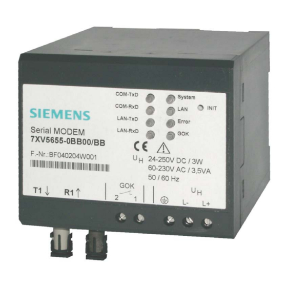
- Page 1 7XV5655-0BB00 Manual C53000-G1176-C175-2 Application Instructions Serial Modem Modem for transmission of serial data or protocols from devices with an RS232/RS485/FO interface via Ethernet Copyright Siemens AG 2004...
-
Page 2: Table Of Contents
English 7XV5655-0BB00 CONTENTS GENERAL INFORMATION..........................3 APPLICATION................................8 DESCRIPTION OF INTERFACES, DIP SWITCHES AND DISPLAYS............11 MOUNTING AND COMMISSIONING ......................16 PRACTICAL SAFETY INFORMATION ......................19 PREPARING THE OPERATING PC OR SERVICE NOTEBOOK..............20 THE CONFIGURATION TOOL .........................34 CONTROL COMMANDS ............................45 DESCRIPTION OF AT COMMANDS........................47 OVERVIEW OF REGISTERS ..........................52 DESCRIPTION OF REGISTERS........................53... -
Page 3: General Information
Siemens office or from the addresses stated on the back of this manual. We should also like to point out that the contents of this product documentation are not part of any previous or existing agreement or legal relationship, nor are they apt to modify such an agreement or relationship. - Page 4 Directives in agreement with the generic standards EN 61000-6-2 and EN 61000-6-4 (for EMC Directive) and with the standard EN 60255-6 (for Low Voltage Directive) by Siemens AG. The device is designed and manufactured for application in industriel environment. The product conforms with the international standards of IEC 60255 and the German regulations of VDE 0435.
- Page 5 Warning The 7XV5655-0BB00 is specifically intended for installation in a switchgear cubicle or distribution box. After installation, the entire area around the terminals must be covered. Only then is the device sufficiently protected against impermissible contact with live parts.
- Page 6 English 7XV5655-0BB00 Warning! Hazardous voltages are present in this electrical equipment during operation. Severe personal injury or property damage can result if the device is not handled properly. Only qualified personnel should work on or around this equipment. The personnel must be thoroughly familiar with all warnings and maintenance procedures of this manual as well as the safety regulations.
- Page 7 English 7XV5655-0BB00 Scope of Supply • Serial Modem, device for DIN rail mounting • Gender changer, 9-way, male-male • CD with manual, configuration tool, and Serial Modem driver • Installation instructions Unpacking and Repacking The devices are packed at the factory to meet the requirements of IEC 60255–21.
-
Page 8: Application
English 7XV5655-0BB00 Application General Scope of Application The Serial Modem is designed for operation in industrial zones and substations. The Serial Modem enables devices with serial interfaces (RS232, RS485, or FO) to convert data to the UDP protocol with error detection and correction and to transmit and receive it via a TCP/IP network. - Page 9 7XV5655-0BB00 Application in Substations A 7XV5655-0BB00 Serial Modem enables a protection unit to exchange serial data via an Ethernet network. The operating PC can also be linked to this Ethernet network via a 7XV5850 office modem or 7XV5655 Serial Modem.
- Page 10 English 7XV5655-0BB00 Features Protocol detection for VDEW / IEC60870-5-101/103 and DIGSI® protocol (similar to IEC60870-5-103), UDP protocol without error detection and correction RS232/RS485 (switchable port) or FO interface for data transfer and modem configuration. Serial baudrate and data format to the terminals can be set from 2400 Bd to 115.2 kBd with data formats 8N1, 8N2, 8E1.
-
Page 11: Description Of Interfaces, Dip Switches And Displays
The terminal device (protection unit) (e.g. a SIPROTEC 4 unit) or a further device from the ® Siemens accessory program (e.g. a 7XV5300 or 7XV5450 star coupler for operating two or more SIPROTEC devices) can be connected directly to ®... - Page 12 The data transfer rate is that of the RS232 interface. The terminal device (e.g. a SIPROTEC ® unit) or a further device from the Siemens accessory program (e.g. 7XV5300 or 7XV5450 star coupler for operating two or more SIPROTEC devices) can be ®...
- Page 13 English 7XV5655-0BB00 To use the FO interface, DIP switch S2-2 must be set to match the FO idle state of the communications partner (ON or OFF). DIP switch S2-1 for RS232/485 selection must be set to RS232. DIP switches S1-1 and S1-2 must be set to OFF (see Fig. 5).
- Page 14 English 7XV5655-0BB00 INIT Button The INIT button is for resetting the modem to its factory (default) settings and should only be operated by technically qualified personnel. It can be used to set a defined baudrate locally for service work. The default baudrate is 9600 8N1.
- Page 15 English 7XV5655-0BB00 Meaning of Displays The LEDs indicate the state of the device and have the following meaning: Fig. 6: Connectors, displays (LEDs) and INIT button • DR Device run: switched on, operating voltage OK device operational • System Slow flashing (approx. 1Hz): no connection to the terminal device fast flashing (approx.
-
Page 16: Mounting And Commissioning
English 7XV5655-0BB00 Mounting and Commissioning This section is intended for experienced commissioning technicians. They must be familiar with the commissioning of protection and control systems, with the management of power systems and with the relevant safety rules and standards. Some hardware adaptations to the system data may be necessary. - Page 17 English 7XV5655-0BB00 Connecting the Device This describes connecting all data and power supply lines that are necessary for safe operation. In the case of electrical installation, follow the rules governing erection of power current equipment. Warning Always use wire end ferrules for stranded conductors.
- Page 18 English 7XV5655-0BB00 Connection to the Sub D connector The Sub D connector must be screwed tight after connection. The pin assignment is to be found in this manual (page 66 ff). Ethernet Connection The Serial Modem is connected to the network, i.e. a router or switch, using a patch cable via the RJ45 (10BaseT) connector.
-
Page 19: Practical Safety Information
English 7XV5655-0BB00 Practical Safety Information As is the case for all electrical equipment, there are some basic safety precautions to be taken. These safety precautions are primarily for your own safety but also prevent damage to the device. Settings not described in the manual and changes to the device electronics must only be carried out by an authorised vendor. -
Page 20: Preparing The Operating Pc Or Service Notebook
English 7XV5655-0BB00 Preparing the Operating PC or Service Notebook Before commissioning the Serial Modem, you must take the following precautions on the operating or service notebook. • Installation of the Modem Driver To operate the Serial Modem in a WINDOWS® application requiring a dial-up link, the modem driver must first be installed in the WINDOWS®... - Page 21 English 7XV5655-0BB00 Installing the Modem Driver Before you can use the Serial Modem in a WINDOWS® application, the modem driver must first be installed in the WINDOWS® Control Panel. The modem driver ipetherModem_v2.inf for the Serial Modem is to be found on the enclosed DVD SIPROTEC DOWNLOAD-AREA offline "...
- Page 22 English 7XV5655-0BB00 The modem must be selected manually. This is done by placing a checkmark in Don't detect my modem; I will select it from a list checkbox. Click Next >. Install a new modem from Have Disk… Select the correct...
- Page 23 English 7XV5655-0BB00 The modem driver is on CD Manuals_7XV5 in path Accessories \ 7XV5655 \ Driver \ … Select the driver file ipetherModem_v2.inf Open Continue with 23 / 77 C53000-G1176-C175-2...
- Page 24 English 7XV5655-0BB00 Select modem model Siemens – ipEtherModem Ignore the fact that this driver is not digitally signed. Next > Select the serial port, e.g. COM1 to which the Serial Modem will later be connected. Next > This warning by WINDOWS® XP can be ignored.
- Page 25 English 7XV5655-0BB00 Installation is completed with Finish Overview of the installed modem drivers in WINDOWS®. With Properties, you can check settings of the selected modem and change them. Here you can set the maximum baudrate to the end device. Please follow the application instructions for...
- Page 26 English 7XV5655-0BB00 Installing the Configuration Tool For easy exe" file modem configuration using the configuration tool via the Ethernet interface, the tool must be installed on the operating PC from the enclosed DVD “SIPROTEC DOWNLOAD-AREA offline " under "Accessories \ 7XV5655 \ Configtool \ Setup.exe".
- Page 27 English 7XV5655-0BB00 "Browse…" can change the preset installation path. Under "Disk Cost…" you can display the free disk space on the available drives. The application can be released for one user or all users of the PC. Continue with "Next >"...
- Page 28 English 7XV5655-0BB00 Configuring the LAN Interface of the Operating PC There are two ways of configuring the Serial Modem on a PC using the configuration tool via its Ethernet interface: Direct PC <–> modem LAN connection with "cross-over patch cable"...
- Page 29 English 7XV5655-0BB00 The IP address is set under "Internet Protocol (TCP/IP)" by clicking the "Properties" button. A checkmark in "Show icon in notification area when connected … " has an icon display the status of the connection in the notification area.
- Page 30 English 7XV5655-0BB00 In the "Local area connection status" window, go to "Support" if you want to check the settings of the LAN interface. Close the window again with the "Close" button. After you have started the configuration tool, the connected modem is found automatically and can be configured (see Section "Configuration tool").
- Page 31 English 7XV5655-0BB00 PC <–> modem LAN connection in an existing network The modem is connected with a patch cable (not cross-over) to a hub or switch in an existing network to which the operating PC is also connected. The PC usually obtains a free IP address from the server.
- Page 32 English 7XV5655-0BB00 Using "HyperTerminal" via the Serial Interface of a PC This terminal program is supplied as a standard part of the operating system, e.g. WINDOWS® 98, WINDOWS® ME, WINDOWS® 2000 and WINDOWS® XP. Start HyperTerminal under: "Start Programs Accessories Communications HyperTerminal"...
- Page 33 English 7XV5655-0BB00 If the Serial Modem is connected to the PC, it is possible to read out the current settings with the AT&V command. These settings can be changed by entering "Hayes commands". See the section on "Control Commands" for further information.
-
Page 34: The Configuration Tool
English 7XV5655-0BB00 The Configuration Tool Configuring the Serial Modem with the Configuration Tool The configuration tool provides a practical way of making "basic settings" such as modem name, IP address and baudrate of the Serial Modem. For this purpose, the configuration tool is started and finds all Serial Modems in the same network segment which it then lists in a table. - Page 35 English 7XV5655-0BB00 Currently configured COM port (not available for Serial Info Modems) If this entry is "true", the device is in connection mode and it In Use is not possible to make changes to parameterisation. If this entry is "False", the device will no longer be found. It...
- Page 36 English 7XV5655-0BB00 Set IP Address Enter a fixed IP address, Subnet-Mask and Default-Gateway for operation of the Serial Modems in a network. If the allocated IP-address and the Subnet-Mask are not compatible the properties can not be changed any more. In such an event please change the settings.
- Page 37 English 7XV5655-0BB00 Upload Firmware Look for the new firmware version and import with "Open" or by double-clicking. The firmware update resets the modem to its factory settings (default values). Passwords are not reset. If during the firmware update the message „Can’t upload Firmware.
- Page 38 English 7XV5655-0BB00 Add Device Manually If the Serial Modem is connected behind a router, it is not found automatically but must be added manually ("Add Device manually"). This is done by entering its IP address in the field. If the device can be accessed at this address, it is put in the list.
- Page 39 English 7XV5655-0BB00 Properties Double-clicking the device entry in the overview window displays a dialog box in which further settings can be made. A detailed dialog box consisting of six setting tab cards opens: TCP/IP Settings "Info" displays the MAC address,...
- Page 40 English 7XV5655-0BB00 Modem Settings Under "modem", you can set how the modem behaves. Setting a checkmark activates the function in question. Answer incoming calls activates the automatic call acceptance after the first dialling tone. Local Echo on (E1) switches on the modem's echo.
- Page 41 English 7XV5655-0BB00 RS232 Interface Settings (RS232 / RS485 / FO) These settings adapt the serial interface of the Serial Modem to that of the terminal device. The terminal device may, for example, be an operating PC or protection unit with a serial interface (SIPROTEC ).
- Page 42 English 7XV5655-0BB00 TC57 Settings (Ethernet) If a frame in TC57 format is received via the RS232 interface, it is sent immediately via the Ethernet without a "timeout". This procedure clearly increases the performance of the connection and ensures uninterrupted transmission of frames.
- Page 43 English 7XV5655-0BB00 INet Info This window provides up-to-date network information. Trace Route Ping The "Start" button transmits a ping to the serial hub to ascertain the throughput time of the telegrams in the network. Throughput time + 10ms = ideal "Total Timeout" here <10ms + 10ms = 20ms...
- Page 44 English 7XV5655-0BB00 About This window provides information about the program version and the date of creation of this configuration tool. If the PC has Internet access, you can double-click the image for direct access to our Download Area. All up-to-date documents, drivers and updates for our products are available there.
-
Page 45: Control Commands
English 7XV5655-0BB00 Control Commands Your Serial Modem is the latest in Ethernet modems and is equipped with the AT command set. To enter the AT commands, you require a terminal program, e.g.: "HyperTerminal". This program is part of MS WINDOWS® and can be started under "Start - Programs - Accessories". - Page 46 English 7XV5655-0BB00 After the three Escape characters have been entered, the modem switches to command mode. There is, however, no transmission interrupt before a valid command line is recognised. Status: Online Mode Command: +++ [2-second pause] Status: Command Mode Command: ATO...
-
Page 47: Description Of At Commands
English 7XV5655-0BB00 Description of AT Commands Hayes Commands The Hayes command set (AT commands) has over time developed into an industry standard among modem manufacturers. In addition to these, manufacturers use their own modem commands that are specific to the brand. Some of these commands are not compatible with modems of other manufacturers. - Page 48 English 7XV5655-0BB00 Returns to data mode. Note: By entering +++ you can switch to command mode during a modem connection, where AT commands can be executed. This does not break off the connection. The ATO command terminates the command mode.
- Page 49 English 7XV5655-0BB00 Activates/deactivates modem echo. ATQ0 send echo ATQ1 no echo Valid IP addresses for call accept. ATRnumber=value (number = 0-9) ATR2=192.168.120.23 ATR2? read out register (see also AT&R) Ten IP addresses, for which calls are accepted, can be defined in the password configuration mode (registers 110-119).
- Page 50 English 7XV5655-0BB00 Change passwords. ATZ=master password Changes the master password (default empty) ATZ1..9=User password Assign user password. ATZ1? Queries the set password for checking ATZ=<Enter> Deletes the master password. ATZ1..9=<Enter> Deletes the user password. Entries are only possible in password configuration mode (see ATP).
- Page 51 English 7XV5655-0BB00 Ends password configuration mode AT&P Only possible in password configuration mode (see ATP). Outputs a list of all set IP addresses for call accept. AT&R Only possible in password configuration mode (see ATP and ATR). Displays the current configuration.
-
Page 52: Overview Of Registers
English 7XV5655-0BB00 Overview of Registers The modem has internal registers, enabling you to modify its configuration (see also ATS command). Register Definition Default Options Auto answer [0..9] rings Number of rings Read only Escape character ASCII CR character 0x0d ASCII... -
Page 53: Description Of Registers
English 7XV5655-0BB00 Description of Registers Automatic call accept Range 0 … 9 rings Default In the S0 register, you can set the automatic call accept (auto answer). If S0 > 0, each incoming call is automatically answered. The value in S0 defines the number of rings the modem waits before it auto answers. - Page 54 English 7XV5655-0BB00 Linefeed Character Range 0 … 127 decimal Default 10 (Linefeed) Register S4 defines the linefeed character. Backspace Character Range 0 … 32, 127 decimal Default 8 (Backspace) Register S5 defines the backspace character. Inactivity Timer Range 0 … 255 (from device software 14.x on)
- Page 55 English 7XV5655-0BB00 Data Bits Range 7 … 8 Default In the S33 register, you can set the number of data bits. 7=7 Bits 8=8 Bits Format 7N1 (7 data bit and no parity) is invalid Stop Bits Range 1 … 2 Default In register S34, you can set the number of stop bits.
- Page 56 English 7XV5655-0BB00 Char Timeout (Character Distance) Range 5..255 ms Default 10 ms In register S36, you can set the character distance, i.e. the character interval. If the time between two received characters (bytes) is greater than the defined character timeout, all bytes received so far are sent to the Ethernet...
- Page 57 English 7XV5655-0BB00 Select TC57 Type Range 0 ... 3 Default The IEC 60870–5–1 and IEC 60870–5–2 standards define four standard frame formats for the data link layer: 0 = Format FT 1.1 2 = Format FT 2 1 = Format FT 1.2 3 = Format FT 3 Frame formats FT 1.2, FT 2 and FT 3 have a frame of fixed length.
- Page 58 English 7XV5655-0BB00 Password Blocking Time Range 0 ... 255 minutes Default 3 (minutes) The blocking time is set in register 82. After three incorrect password entries the modem allows no further password request until the blocking time has elapsed. (0 = function deactivated).
- Page 59 English 7XV5655-0BB00 S102 Auto Remote Range xxx.xxx.xxx.xxx Default 0.0.0.0 In register S102, you can set the auto remote partner. Enter the IP address of the "communication partner" to which a connection is to be established automatically (leased line). After a connection break-off there is an automatic attempt at restoring the connection. The connection set-up and take-down can be controlled via DTR (see AT&D).
-
Page 60: Result Codes
English 7XV5655-0BB00 Result Codes System return code as a character string or digits (see AT command ATV). If system result codes are not suppressed with ATQ1. Char string Digit Definition Command line processed CONNECT Successful connection setup RING Incoming call... - Page 61 English 7XV5655-0BB00 "Character Distance" is the maximum interval between two received characters. If this is exceeded, all characters received so far are transmitted into the Ethernet. The default value is 5 ms. Total read timeout Total read timeout Character timeout No transmission.
- Page 62 English 7XV5655-0BB00 Protocol Code TC57 for Transmission into the Ethernet This procedure considerably enhances transmission rates when TC57 compatible protocols are transmitted. If the RS232 interface detects a protocol packet of this type, it is transmitted as a block via the Ethernet immediately without waiting for a timeout to elapse.
-
Page 63: Setting Up Password Protection
English 7XV5655-0BB00 Setting Up Password Protection The Serial Modem features extensive password protection. This protects the called modem (substation modem) from unauthorised external access. The password is always transmitted encrypted via the Ethernet. Password protection can only be configured after entering the master password in the password configuration mode with the terminal program via the serial interface, i.e. -
Page 64: Selecting A Password-Protected Serial Modem
English 7XV5655-0BB00 Password Blocking Time A password blocking time can be defined in register S82. After three incorrect password entries the modem allows no further password request until the blocking time has elapsed. ATS82=2 blocking time of two minutes Saving Changes: All changes are only applied when they are saved. -
Page 65: Valid Ip Addresses For Call Accept
English 7XV5655-0BB00 Valid IP Addresses for Call Accept To enhance the security of the called Serial Modem, the user can restrict call acceptance only to a number of permanently stored IP addresses. Activating Password Configuration Mode The settings can only be made in password configuration mode. You can enter this mode for the first time by entering ATP<Enter>. -
Page 66: Pin Assignment
English 7XV5655-0BB00 Pin Assignment The cables for RS232 and RS485 are connected to the same port and selected using the DIP switches. RS232 Interface SERIAL PORT Richtung Definition 9-pin SubD connector Screen INPUT RXD Receive Data OUTPUT TXD Transmit Data... - Page 67 English 7XV5655-0BB00 Ethernet Interface Ethernet connector RJ 45 Name Definition Transmit Data+ Transmit Data- Receive Data+ Not connected Not connected Receive Data- Not connected Not connected Ethernet RJ45 connector Auxiliary Voltage and Earth Connection 3-way terminal block Name Definition Vaux...
- Page 68 English 7XV5655-0BB00 Connecting Cable RS232 connection options: 1) PC/laptop to the Serial Modem (office) plug in serial DIGSI cable directly 2) PC/laptop to the protection unit plug in serial DIGSI cable directly 3) Station modem to SIPROTEC 4 or plug in serial DIGSI cable via gender...
-
Page 69: Technical Data
English 7XV5655-0BB00 Technical Data 24 V – 250 V DC +/-20 % Auxiliary voltage 60 V – 230 V AC +/-20 % , 45-65 Hz, 2.5 W DC Power input 14 VA AC T 2A/250 V AC and 250 V DC Line-side fuse acc. - Page 70 English 7XV5655-0BB00 RS232 and RS485 Connection type 9-way SubD connector, 4/40 UNC screw connection Pin assignment See Pin Assignment Cable length RS232 Max. 10 m / 3280 feet Baud rate 2400 to 115200 baud, Rxd, Txd Parity : None, Even, Odd, Mark, Space...
- Page 71 3pos./neg. surges at 5s intervals interfaces, class III Warning The 7XV5655-0BB00 is specifically intended for installation in a switchgear cubicle or distribution box. After installation, the entire area around the terminals must be covered. Only then is the device sufficiently protected against impermissible contact with live parts.
- Page 72 English 7XV5655-0BB00 - Relay output Common mode; 2 KV; 42 Ω; 0.5 µF Differential mode : 1 KV; 42 Ω; 0.5 µF 10 V; 150 KHz – 80 MHz; 80 % AM, 1 KHz Conducted RF, amplitude-modulated IEC61000-4-6, Class III 0.5 mT;...
- Page 73 English 7XV5655-0BB00 Mechanical tests, vibration and shock stress - during transport Sinusoidal, 5 to 8 Hz : 7.5 mm ampl. Vibration IEC 60255-21-1, Class 2 8 to 150 Hz : 2 g accel., IEC 60068-2-6 20 cycles in 3 orthogonal axes Semi-sinusoidal, 15 g accel., 11 ms duration...
-
Page 74: Dimensions
English 7XV5655-0BB00 Dimensions 74 / 77 C53000-G1176-C175-2... -
Page 75: Ordering Information
English 7XV5655-0BB00 Ordering Information Name Order No. Serial Modem 7 X V 5 6 5 5 0 B B 0 0 10BaseT connection 10/100 Mbits, RJ45 connector Serial RS232/485 interface 9-way Sub D connector Gender changer (male-male) FO interface, ST connection DIN rail mounted device for 35mm rail Aux. - Page 76 Weitergabe sowie Vervielfältigung dieser Unterlage, Verwertung und Mitteilung ihres Inhalts nicht gestattet, soweit nicht ausdrücklich zugestanden. Zuwiderhandlungen verpflichten zu Schadenersatz. Alle Rechte für den Fall der Patenterteilung oder GM–Eintragung vorbehalten. The reproduction, transmission or use of this document or its contents is not permitted without express written authority.
- Page 77 Hinweise und Fragen zu diesem Produkt Defekte Geräte senden Sie bitte an richten Sie bitte an folgende Adresse: folgende Adresse: Siemens AG Siemens AG Power Transmission and Distribution Power Transmission and Distribution Energy Automation Energy Automation PTD Customer Support Center PTD EA P ACC2 Rückwarenabteilung...
Need help?
Do you have a question about the 7XV5655-0BB00 and is the answer not in the manual?
Questions and answers