
Related Manuals for Satelec X-Mind DC


Summary of Contents for Satelec X-Mind DC
- Page 1 ® X-Mind Installation manual / Manuel d’installation Installationshandbuch / Installatiehandleiing...
-
Page 2: Introduction
X-Mind Intraoral X-ray system at constant potential INSTALLATION & MAINTENANCE MANUAL This manual should always be kept in proximity to the device... -
Page 3: Table Of Contents
5.4 ASSEMBLING THE PANTOGRAPH-TYPE ARM page 5.5 CONNECTION TO THE FEEDING TERMINAL BOARD page page 5.6 ASSEMBLING THE TUBEHEAD 5.7 BALANCING THE PANTOGRAPH-TYPE ARM page 5.8 ASSEMBLING THE “X-Mind DC” TIMER page page 5.9 TIMER ELECTRIC CONNECTION CONTROL PANEL page SYSTEM CONFIGURATION page... -
Page 4: Preliminary Information
PRELIMINARY INFORMATION Before beginning to use the “X-Mind DC” X-ray system, instructions contained herein should be carefully read and followed so as to obtain the best possible performance. Always pay close attention to the CAUTION, WARNING, and PLEASE NOTE messages when operating the system. -
Page 5: Installer Information
The installer is responsible for the installation, with regards to the system safety and operation. For safe and reliable installation of the “X-Mind DC” X-ray system it is advisable to: Check that the voltage mentioned in the rating plate matches the line voltage Install the “X-Mind DC”... -
Page 6: X-Mind Dc" X-Ray System
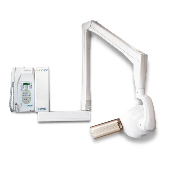
1. “ ” X-RAY SYSTEM X-Mind DC The “X-Mind DC” X-ray system (Fig. 1) consists of: TUBEHEAD SPACER CONE PANTOGRAPH-TYPE ARM TIMER WALL PLATE BRACKET OPTIONAL − long 12” (31 cm) cone − short 8” (20 cm) cone − long cone 12” (31 cm) with a rectangular section sized 44x35mm −... -
Page 7: Identification Tags
The identification tags on the tubehead, on the timer and on the cone indicate the model name, the serial number, the manufacturing date and the symbols of the main technical characteristics. ID TAG OF THE “X-Mind DC” TUBEHEAD ID TAG OF THE “X-Mind DC”... -
Page 8: Overall Dimensions
3. OVERALL DIMENSIONS Fig. 1A, 1B, 1C give the overall dimensions of the possible supply conditions: SHORT BRACKET (optional) length 41 cm 16.2” STANDARD BRACKET length 82,5 cm 32.5” LONG BRACKET (optional) length 110 cm 43.5” SHORT BRACKET 41 cm Fig. - Page 9 Fig. 2, 3A, 3B, 3C e 4 show the typical dimensions of the X-ray system: STANDARD BRACKET 82.5 cm Fig. 2 ® ®...
- Page 10 STANDARD BRACKET 82.5 cm Fig. 3A Fig. 3B Fig. 3C SHORT BRACKET 41 cm LONG BRACKET 110 cm ® ®...
- Page 11 Fig. 4 ® ®...
-
Page 12: Installation Specifications
4. INSTALLATION SPECIFICATIONS WARNING Prior to installing the X-ray system the Office Owner must ascertain that: the environment, the electrical system and the power supply comply with the requirements specified, otherwise he must provide the required adjustment works. ENVIRONMENT REQUIREMENTS a. - Page 13 ELECTRICAL LINE REQUIREMENTS The electrical line must be "single-phase" type It is essential that a 16A – 250V, magnetothermal differential switch be fitted upstream of the X-ray system, with differential protection In<= 30mA (refer to §20 “ATTACHMENTS”) The power cords of the timer and the tubehead connection conductors with must be two-pole + ground, and in proportion to the length of the power cord, as shown in Chart 2 CHART 2...
- Page 14 ELECTRICAL CONNECTIONS WARNING Prior to installing the X-ray system, it is advisable that all the electrical connections be in place. Timer electric connections CAUTION According to the relevant standard, the timer must be installed in a position allowing the operator to always control the X-ray exposure. On the timer installation wall, suitable conduits for the following electric cables must be provided, pursuant to the electrical installation diagram (refer to §20 “ATTACHMENTS”): Timer electrical cables...
-
Page 15: Installation
5. INSTALLATION CAUTION The “ X-Mind X-ray system must be installed by professionally trained technicians, who must be able to certify their work with a Statement of Compliance. WARNING Prior to installing the X-ray system, it is advisable to ensure that all needed requirements have been met (refer to §4 “INSTALLATION SPECIFICATIONS”) 5.1 UNPACKING ... -
Page 16: Assembling The Wall Plate
5.2 ASSEMBLING THE WALL PLATE WARNING To fix the wall plate, DO NOT use plastic or rubber anchor screws. For cement or solid/hollow brick walls, use metal anchor screws Ø12 (NOT included). ASSEMBLY INSTRUCTIONS (Fig. 6) 1. Take the wall plate out of the packaging (refer to Fig. 5) and take the drilling template 2. - Page 17 Fig. 6 ® ®...
-
Page 18: Assembling The Bracket
5.3 ASSEMBLING THE BRACKET PLEASE NOTE The brackets come in the following lengths: 41 cm - 82,5 cm - 110 cm The 82.5 cm and 110 cm brackets are provided with a stop key (Fig. 7A and 7B) to prevent the electrical cable from twisting. - Page 19 After fixing the plate to the wall, assemble the bracket, using the following procedure (Fig. 8): 1. Take the bracket out of the packaging (refer to Fig. 5) 2. Insert the bracket pin into the wall plate (upwards) 3. Insert the supporting rest Fig.
-
Page 20: Assembling The Pantograph-Type Arm
5.4 ASSEMBLING THE PANTOGRAPH-TYPE ARM ASSEMBLY INSTRUCTIONS (Fig. 9) 1. Take out the pantograph-type arm from the packaging (refer to Fig. 5) 2. Remove the bracket plug by unscrewing the set screw 3. Insert the bracket guard wafer 4. Insert the pantograph group cable into the washer and then the pantograph pin Fig. -
Page 21: Connection To The Feeding Terminal Board
5.5 CONNECTION TO THE FEEDING TERMINAL BOARD CAUTION For electrical safety, it is essential that the ground conductors be correctly connected. WARNING The length of the electrical cable and of the communication cable is suitable for 82.5 cm brackets. DOT NOT tamper with the terminals arrangement when 41 cm long brackets are used. The excess cable must be stored in the housing provided. - Page 22 OPERATING INSTRUCTIONS (Fig. 10) Remove the terminal board cover by unscrewing the set screw Fig. 10 ® ®...
- Page 23 2. Proceed with the electrical connection as shown in Fig. 11 IMPORTANT ! Fig. 11 TERMINAL BOARD CONNECTION DIAGRAM BROWN L (line) YELLOW GREEN T (ground) BLUE N (neutral) BLACK COMMUNICATIONS COMMUNICATIONS YELLOW GREEN T (ground) YELLOW GREEN T (ground) THE COMMUNICATIONS CABLES ARE NOT POLARIZED Connect the pantograph cable shield to the grounding potential Connect the wall plate to the grounding potential...
-
Page 24: Assembling The Tubehead
5.6 ASSEMBLING THE TUBEHEAD ASSEMBLY INSTRUCTIONS Remove the tubehead from the packaging (refer to Fig. 5) Check that all the rating data match the power supply voltage Remove both guards from the pantograph-type arm by loosening the appropriate screws (Fig. 12) Fig. - Page 25 Insert the tubehead pin into the pantograph head (Fig. 14A) and insert the support (Fig. 14B) Fig. 14A Fig. 14B Check that during insertion, the pin of the rotation prevention device is correctly inserted into the seat located on the pantograph head (Fig. 15) Fig.
- Page 26 Couple the pantograph and tubehead connectors and insert them into their seats (Fig. 16) Fig. 16 ® ®...
-
Page 27: Balancing The Pantograph-Type Arm
5.7 BALANCING THE PANTOGRAPH-TYPE ARM CAUTION The pantograph-type arm must be adjusted only when the tubehead is assembled . WARNING To prevent damage to the internal mechanism while making adjustments and executing the balancing tests, the adjustment key must not be left in place. WARNING The key provided must be carefully stored. - Page 28 Procedure to be followed to correctly balance the pantograph-type arm (refer to Fig. 17): “ARM A” BALANCING PLEASE NOTE The pantograph-type arm is supplied with “ARM A” already preloaded. “ARM B” is supplied unloaded for safety reasons. “ARM B” BALANCING For correct balancing, proceed as follows: 1.
- Page 29 Upon completion of balancing: Insert the movable finish (A) between the pantograph-type arm guard and the metal frame (Fig. Fig. 18 2. Insert the pins of the guards into their slots; then position them and ensure that the movable finish is coupled to the guards (Fig.
-
Page 30: Assembling The "X-Mind Dc" Timer
® 5.8 ASSEMBLING THE “X-Mind DC” TIMER CAUTION Check that the cable conduits are present in the timer installation wall; check the compliance power supply with installation specifications (refer to §.4 “INSTALLATION SPECIFICATIONS”). CAUTION Check that the rating data match the power supply voltage. ASSEMBLY INSTRUCTIONS (Fig. - Page 31 7. Withdraw the 26-pole connector from its seat to release both timer guards (Fig. 21) 26-POLE CONNECTOR Fig. 21 8. Insert the electrical feeding cables into the hole (Fig. 22) FEEDING CABLE INLET HOLE INLET HOLE FOR THE TUBEHEAD(S) RX SIGNALING LAMP(S) FOR EXTERNAL USE CABLE REMOTE CONTROL BUTTON(S) Fig.
-
Page 32: Timer Electric Connection
5.9 TIMER ELECTRIC CONNECTION CAUTION Before proceeding with connections, the power supply must be cut off. CAUTION If the equipment is mounted on metal walls, these must be connected to the grounding circuit. WARNING While performing the connection, always comply with the PHASE – NEUTRAL polarity. WARNING While stripping the cables, be careful that small copper wires do not fall on the printed circuit and cause short circuits or malfunctioning. - Page 33 3A-3B 4A-4B Fig. 23 The electronic card terminal boards control the following functions: TUBEHEAD N° 1 CONTROL BUTTON and/or REMOTE CONTROL BUTTON TUBEHEAD N° 2 CONTROL BUTTON and/or REMOTE CONTROL BUTTON TUBEHEAD N° 1 RX SIGNALING LAMP FOR EXTERNAL USE TUBEHEAD N°...
-
Page 34: Control Panel
6. CONTROL PANEL The control panel is the user's interface, from which the operator can: use the keys to select the operating parameters to change the exposure times displayed to store the new customized exposure times use the “green LED” light indicators to check the timer operating conditions ... - Page 35 MAIN SWITCH CONTROL BUTTON X-RAY DISPLAY TO DECREASE TO INCREASE EXPOSURE EXPOSURE TIME TIME TUBEHEAD TYPE X-RAY DISTANCE INDICATOR INDICATOR TUBEHEAD X-RAY VOLTAGE SELECTION INDICATOR SELECTION OF MEMORY PATIENT’S PHYSIQUE TYPE UPPER MAXILLARY TEETH X-RAY CURRENT LOWER MANDIBLE INDICATOR TEETH X-RAY OCCLUSAL EXAM OUTPUT SIGNAL...
-
Page 36: System Configuration
7. SYSTEM CONFIGURATION ® X-Mind The “ ” X-ray system is factory configured for “standard mode” operation which determines: pressing the RX button on the control ® X-Mind panel causes the LED 1 button to light up, No. 2 “ ”... - Page 37 ** IF THE LONG 12” (31 cm) CONE IS USED ** tubehead no. 1 ■ “dc” type tubehead ■ tube head .no. 2 ■ “dc” type tubehead ■ control button no. 2 ■ 12” cone (31cm) ■ not available ■ not available ■...
-
Page 38: Changing The Configuration
8. CHANGING THE CONFIGURATION CAUTION This must be done by the installer. WARNING To make the changes operative, turn off the timer and then turn it on again. To change the configuration, the timer’s dip switch positions ( )must be changed: PARAMETER SWICH TUBEHEAD No. - Page 39 CHANGING THE NUMBER OF TUBEHEADS INSTALLED To change the number of tubeheads installed, move dip switch no. 1 or no. 3 a. If the tubehead is connected to the X-RAY 1 terminal board, put dipswitch no. 1 in the ON position; if not, put it in the OFF position b.
-
Page 40: Start-Up
9. START UP CAUTION When all connections are completed, the installer must check the system’s electrical and operating safety. For further information, see the USER'S MANUAL. TURN ON THE TIMER to power up the X-ray system a. Bring the "MAIN SWITCH" located on the upper part of the timer to the “I”... -
Page 41: Checking The Installation
10. CHECKING THE INSTALLATION OPERATING INSTRUCTIONS CHECKING THE CONFIGURATION On the control panel, check that all LEDs corresponding to the required configuration are lit; if not, change them. (refer to § 7 “SYSTEM CONFIGURATION” and § 8 “CHANGING THE CONFIGURATION” ) CHECKING THE TIMER OPERATION a. - Page 42 CHECKING THE POWER ABSORBED BY THE X-RAY SYSTEM To check the power absorbed by the radiographic system a tester must be used, in the mode ampmeter in “AC” a. Connect the instrument to the power supply line (refer to § 5.9 “TIMER ELECTRIC CONNECTION”) b.
-
Page 43: Checking The Exposure Factors
11. CHECKING THE EXPOSURE FACTORS OPERATING INSTRUCTIONS RADIOGRAPHIC VOLTAGE (kVp) The radiographic high voltage is measured using a calibrated "non-invasive" instrument Line Voltage = nominal V ±15% with an initial delay of 50 m. sec. Max Voltage Drop = 3 % SET TECHNICAL kVp = 60 - 70 VALUES... -
Page 44: Diagnostics
12. DIAGNOSTIC DC” X-ray system allows the installer to set or display some of the timer’s functional The “X-Mind parameters: To set the parameters, the installer must: a. Turn off the timer Simultaneously press and keep the following keys depressed: (45) + (43) LOWER MANDIBLE PREMOLAR... -
Page 45: Calibration
13. CALIBRATION CAUTION During this operation there is X-ray output. All the safety measures relevant to radioprotection must be observed. If necessary, “ X-Mind DC ” can be calibrated. The relevant procedure is as follows: a. Switch off the timer b. -
Page 46: Error Messages
14. ERROR MESSAGES ® The following chart contains a list of error messages that may appear while the “X-Mind DC” X- ray system is operating. The chart also includes the causes of the error messages and what to do to resolve them. Error Cause Solution... - Page 47 THE TUB HEAD REPEAT THE EXPOSURE OR HAS NOT COMPLETED THE EXPOSURE CALL THE “SUPPORT DEPARTMENT” FREQUENCY CALL THE “SUPPORT DEPARTMENT” OR REGULATION PROBLEM THE TUBEHEAD CALIBRATE OR IS NOT CALIBRATED CALL THE “SUPPORT DEPARTMENT” EEPROM DATA NOT PROPERLY SAVED CALL THE “SUPPORT DEPARTMENT”...
-
Page 48: Fuse Replacement
15. FUSE REPLACEMENT The timer’s electronic equipment is protected by 4 fuses located on the electronic card. To replace them, proceed as follows (Fig. 25): Cut off the power supply Temporarily remove the timer’s guard by removing the adjusting Determine the fuse to be replaced (Fig. 26) Remove the plastic protector (Fig. -
Page 49: Maintenance
16. MAINTENANCE To guarantee the X-ray system’s safety, the following checks must be carried out: CAUTION The owner is responsible for arranging and respecting the maintenance schedule. The X-ray system must undergo maintenance to check for correct operation every 12 months. -
Page 50: Cleaning Outer Surfaces
The spacer cone may be cleaned with cotton wool soaked in surgical alcohol. 18. IF A REPAIR BECOMES NECESSARY In case of a malfunction, send the defective part to (USING THE ORIGINAL PACKAGING): Satelec S.A.S. Z.I. du Phare B.P. 216 33708 MERIGNAC cedex - France Tel. -
Page 51: Should A Repair Become Necessary
20. ACCESSORIES The manufacturer undertakes to supply, upon request, drawings, circuit diagrams, component parts lists, instructions or other information needed by qualified technical personnel to perform ® repairs on those parts of the “ X-Mind DC ” radiographic system which may be repaired. ... -
Page 52: Attachments
® X-Mind Installation electrical scheme All rights reserved ® ®... - Page 53 ® CODE Q.TY PCS X-MIND SPARE PARTS TUBE HEAD DC XG (1) COPERTURA FORCELLA 29700979 AC/DC XG (2) SET GHIERE FORCELLA 29700980 AC/DC XG (3) FORCELLA 29700777 AC/DC XG (4) LIMITATORE DI ROTAZIONE 29700750 DC XG (5) GUARNIZIONE 27500959 DC XG (6) SCHEDE ARIA 29700981 DC XG (7) COPERTURA SCHEDA ARIA 29700982...
- Page 54 ® CODE Q.TY PCS X-MIND SPARE PARTS LIGHT XG LIGHT (1) GUSCIO INF & SUP 29700977 XG LIGHT (2) PORTALAMPADA 33400372 XG LIGHT (3) LAMPADINA 230V 15W 33300352 XG LIGHT (3) LAMPADINA 115V 15W 33300390 XG LIGHT (4) SCHEDA 230V 39200354 XG LIGHT (4) SCHEDA 115V 39200353...
- Page 55 ® CODE Q.TY PCS X-MIND SPARE PARTS XG ECB (1) GUSCIO INF & SUP 29700978 SCHEDA COMANDO CON PULSANTE E LED 39700303 XG ECB (3) INTERRUTTORE A CHIAVE 35100298 ...
- Page 56 ® CODE Q.TY PCS X-MIND SPARE PARTS TIMER AC/DC XG TIMER (1) DIMA 24200883 AC/DC XG TIMER (2) SCHEDA CONTROL 39200306 AC/DC XG TIMER (2) SCHEDA CONTROL US 39200307 AC/DC XG TIMER (3) CAVO SPIR 32000325 AC/DC XG TIMER (4) CAVO SPIR DOPPIO 32000359 AC/DC XG TIMER (5) CASSA PULSANTE 29700974...
- Page 57 ® CODE Q.TY PCS X-MIND SPARE PARTS PANTOGRAPH TYPE ARM AC XG B (1) CAVO + CONNETTORE 3 POLI 39700384 DC XG B (2) CAVO + CONNETTORE 5 POLI 39700381 AC/DC XG B (3) GUSCI LATO TESTA 29700990 BRACCIO PANTOGRAFO TIRANTE ANTERIORE 29700460 BRACCIO PANTOGRAFO PORTATIRANTE 29700458...
- Page 58 SPARE PARTS WALL PLATE 350 CODE Q.TY PCS PIASTRA (1) COPERTURA 29700985 AC/DC XG PIASTRA (1) COPERTURA SAT 29700986 PIASTRA LUNETTA 22000176 PIASTRA (3) DIMA 24200984 PIASTRA MURO 350 DEG 29700383 COMPLETO AC/DC XG PIASTRA MURO 350 SAT 29700987 COMPLETO ®...
- Page 59 SPARE PARTS WALL PLATE 350 TOP CODE Q.TY PCS PIASTRA (1) COPERTURA 29700985 AC/DC XG PIASTRA (1) COPERTURA SAT 29700986 PIASTRA LUNETTA 22000176 PIASTRA (3) DIMA TOP 24201002 PIASTRA MURO 350 TOP DEG 29700988 COMPLETO AC/DC XG PIASTRA MURO 350 TOP SAT 29700989 COMPLETO ...
- Page 60 SPARE PARTS BRACKET CODE Q.TY PCS MENSOLA 400 29700380 COMPLETO MENSOLA 800 29700378 COMPLETO MENSOLA 1100 29700379 COMPLETO SPARE PARTS CEILING BRACKET CODE Q.TY PCS MENSOLA PLAFONE 29700382 COMPLETO SPARE PARTS UNIT BRACKET CODE Q.TY PCS MENSOLA RIUNITO 29700381 COMPLETO SPARE PARTS TOP MOUNT BRACKET CODE Q.TY PCS...
- Page 61 ® CODE AANTAL X-MIND WISSELSTUKKEN RICHTARM AC XG B (1) CAVO + CONNETTORE 3 POLI 39700384 DC XG B (2) CAVO + CONNETTORE 5 POLI 39700381 AC/DC XG B (3) GUSCI LATO TESTA 29700990 BRACCIO PANTOGRAFO TIRANTE ANTERIORE 29700460 BRACCIO PANTOGRAFO PORTATIRANTE 29700458 AC/DC XG B (6) TAPPI (set) 29700991...
- Page 62 WISSELSTUKKEN MUURPLAAT 350 CODE AANTAL PIASTRA (1) COPERTURA 29700985 AC/DC XG PIASTRA (1) COPERTURA SAT 29700986 PIASTRA LUNETTA 22000176 PIASTRA (3) DIMA 24200984 PIASTRA MURO 350 DEG 29700383 COMPLETO AC/DC XG PIASTRA MURO 350 SAT 29700987 COMPLETO ® ®...
- Page 63 WISSELSTUKKEN MUURPLAAT 350 TOP CODE AANTAL PIASTRA (1) COPERTURA 29700985 AC/DC XG PIASTRA (1) COPERTURA SAT 29700986 PIASTRA LUNETTA 22000176 PIASTRA (3) DIMA TOP 24201002 PIASTRA MURO 350 TOP DEG 29700988 COMPLETO AC/DC XG PIASTRA MURO 350 TOP SAT 29700989 COMPLETO ®...
- Page 64 WISSELSTUKKEN BEUGEL CODE AANTAL MENSOLA 400 29700380 COMPLETO MENSOLA 800 29700378 COMPLETO MENSOLA 1100 29700379 COMPLETO WISSELSTUKKEN PLAFONDBEUGEL CODE AANTAL MENSOLA PLAFONE 29700382 COMPLETO WISSELSTUKKEN EENHEIDBEUGEL CODE AANTAL MENSOLA RIUNITO 29700381 COMPLETO WISSELSTUKKEN BOVENBEUGEL CODE AANTAL MENSOLA 400 TOP MOUNT 29700620 COMPLETO MENSOLA 800 TOP MOUNT...
- Page 65 SATELEC France MIDDLE EAST SATELEC ACTEON GROUP ACTEON MIDDLE EAST 17 av. Gustave Eiffel - B.P. 216 - F-33708 MERIGNAC cedex Numan Center - 1st Floor N°111 - Gardens Street Tel. +33 (0) 556 34 06 07 PO Box 468 - AMMAN 11953 - JORDAN Fax.
Need help?
Do you have a question about the X-Mind DC and is the answer not in the manual?
Questions and answers
Error message E20 .HOW TO LOCATE ANF REPAIR/CHANGE RELAY.