Haier HP200S1 Installation And Service Manual
Heat pump water heater
Hide thumbs
Also See for HP200S1:
- Operation and installation manual (96 pages) ,
- Operation and installation manual (7 pages)

Related Manuals for Haier HP200S1


Summary of Contents for Haier HP200S1
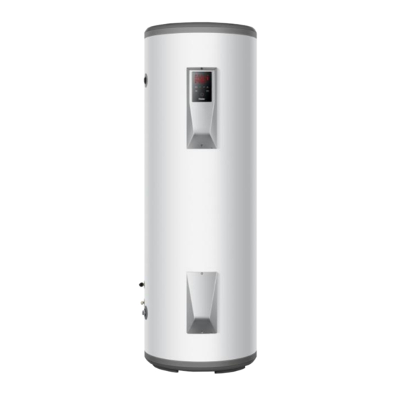
- Page 1 Heat Pump Water Heater Installation and Service Manual Model Please read this manual carefully prior to your use of this water heater. The appearance of the water heater given in this manual is for reference only.
-
Page 2: Table Of Contents
Contents 1. Product safety statement......................3 2. Functionings & principles ....................4 3. Technical parameters ......................5 4. Description of parts and components ................. 6 5. Installation introduction ......................11 6. Operating and settings......................24 7. Faults and protection ....................... 27 8. -
Page 3: Product Safety Statement
1. Product safety statement 1. This appliance can be used by children aged from 8 years and above and persons with reduced physical, sensory or mental capabilities or lack of experience and knowledge if they have been given supervision or instruction concerning use of the appliance in a safe way and understand the hazards involved. -
Page 4: Functionings & Principles
2. Functionings & principles A low-pressure liquid refrigerant is vaporized in the heat pump's evaporator and passed into the compressor. As the pressure of the refrigerant increases, so does its temperature. The heated refrigerant runs through a condenser coil within the storage tank, transferring heat to the water stored there. -
Page 5: Technical Parameters
3. Technical parameters... -
Page 6: Description Of Parts And Components
4. Description of parts and components 4.1 Heat pump structure HP200/300S1... - Page 7 4.2 Exploded view 4.2.1 Exploded view(tank unit)...
- Page 8 4.2.2 Exploded view(external unit) 4.2.3 Heat pump system components 1. Compressor The compressor is to effect a low-temperature low-pressure evaporator refrigerant vapor sucked and compressed into high temperature and pressure of the superheated vapor, and then discharged to the condenser heat exchanger. Inspiratory pipe Wiring box Exhaust pipe...
- Page 9 2. Evaporator Evaporator effects: it makes the liquid refrigerant absorbs heat and is evaporated into steam. 3. Condenser A condenser: high-temperature high-pressure refrigerant vapor is condensed into liquid, during condensation, the refrigerant vapor discharge heat, the heat is absorbed by the heating medium. 4.
- Page 10 5. Filter It’s interior has a filter and desiccant, the desiccant absorbs moisture from the refrigerant, the filter can filter out impurities in the refrigerant. 6. High Voltage Switchgear High-voltage switch is to prevent excessive pressure in the system, thus affecting the life of the system components, high-pressure of the high-voltage switch is 2.8MPa.
-
Page 11: Installation Introduction
9. Refrigerant Heat pump refrigerant is R134a, ODP value is 0, no damage to the ozone layer. R134a refrigerant cans appearance is as follows: 5. Installation introduction 5.1 Installation precaution - Do not install the water heater in the position where exposed to gas, vapours or dust. - Install the tank unit and external unit on a flat, solid surface.The surface can support the machine weight and the condensate water can be drained freely. - Page 12 - There is no sulfur gas or mineral oil existing at the installation place, which may cause corrosion of the machine and the fittings. - The water pipe for the water heater used at temperatures below 0°C shall not freeze. - It shall not be set in rooms where a heating system is used so that heating supply to room will not be affected.
- Page 13 5.2 Installation dimensions (mm)
- Page 14 5.3 Tools for the connection of refrigerant lines a) Group manometer suitable for use with R134a, with charge and vacuum tubes; b) Vacuum pump; c) Torque wrenches for nominal diameter of 1/4 “and 3/8” sizes on both sides to respond to the measures of the pipe unions; d) Flaring clamp ø...
- Page 15 WARNING! Before carrying out any installation check the following: a) Use only copper tubes for air conditioners type (copper tubing for the refrigeration and the conditioning) or copper pipes with proper insulation (at least 6 mm thick), suitable for use with R134a; b) Never use piping with a thickness less than 0.8 mm;...
- Page 16 the tube); e) Insert the threaded brass flare nuts(A) on the pipes in the correct direction; f ) Insert the tube into the flaring tool and make the flange at the end of the connecting pipe, as indicated in the table. After confirming that there are no wrinkles or tears on the flare, connect the pipes using two spanners, being careful not to damage the pipes.
- Page 17 e) close the valves of the pump and shut off (B). Verify that the gauge needle does not move for about 5 minutes. If the needle moves, there are air leaks in the system, then you must check all the tightening and execution of flare at this point repeat the procedure from step c;...
- Page 18 until you hear the coolant leak, and release the pin and close the valve of the the pipe; b) Keep under control the weight of the refrigerant tank through the electronic scale; c) Open the ball valve and to flow the refrigerant gradually; d) After reaching the mass of gas to be loaded close the tap;...
- Page 19 WARNING - Only qualified professionals may carry out electrical connections, always with the power off. - The earthing shall comply with local standards. -The heat pump water heater requires a single phase 16A(HP200S1)/20A(HP300S1) supply requiring a licensed electrician for connecting.
- Page 20 Through poor conditions of the electrical MAINS, shortly voltage drops can appear when starting the EQUIPMENT. This can influence other equipment (eg. blinking of a lamp). If the MAINS-IMPEDANCE Zmax < 0.304 OHM(HP200S1) Zmax < 0.289 OHM(HP300S1) , such disturbances are not expected. (In case of need, you may contact your local supply authority for further information).
- Page 22 5.12 Off-peak power signal wire connection The heat pump water heater requires a single phase 16A(HP200S1)/20A(HP300S1) supply requiring a licensed electrician for connecting.
- Page 23 5.13 Wiring diagram...
-
Page 24: Operating And Settings
6. Operation and functions Display 6.1 Description of the pictograms:... - Page 26 6.2 Installer settings - To open the installer settings, press switch off the system, then press at the same time for 10 seconds. - When menu is open, press to change the value of the settings. - Press to confirm the settings. - Press to close the menu.
- Page 27 7. Checking and maintenance - Installation and maintenance of the appliance must be done by a qualified professional . - Before working on the appliance, Shut down the machine and cut off the power supply . - Do not touch with wet hands. - Maintenance operations are important to guarantee optimum performance and extend the life of the equipment.
- Page 28 Checking the evaporator - Clean the evaporator at regular intervals using a soft-haired brush. - If they are bent. Carefully realign the evaporator using a suitable comb. - Because the evaporator fins is very sharp. Risk of injury on your finger. - Do not damage the fins.
-
Page 29: Faults And Protection
8. Faults and protection 8.1 Fault type... - Page 30 8.2 Fault code identification method...
- Page 34 8.3 Temperature sensor resistance measurement method Temperature sensor resistance measurement method (method of measuring the resistance value of the compressor of the same, but is switched to the small resistance of the interface unit). Multimeter set to Ohms, according to the picture of the method of measuring the resistance of the temperature sensor.
- Page 35 8.4 Check the compressor line is through the current transformer 8.5 Check the signal cable is short-circuited Press the yellow button to switch to the picture, when a short circuit, there is a beep, the resistance is zero. 8.6 Check the tank heater for leaks...
-
Page 36: The Method Of Dismantling Products
Press the yellow button to switch to the picture shown, turn the heating power measurements, if leakage resistance is zero, if not leak, show resistance. 8.7 Check that the power cord L, N lines are in the same order into the leakage protection coil leakage protection coil 9. - Page 37 Remove it 9.2 Remove the Control panel Use a screwdriver to remove the screws Remove it...
- Page 38 Controller panel Off-peak power switching signal Display panel Tank temperature sensor white Evaporator air intake temperature sensor grey sensor red Exhaust temperature Ambient temperature sensor white sensor yellow...
- Page 39 9.3 Remove the motor and fan 2. remove the remove motor 1. remove the screw 9.4 Remove the Magnesium rod Off the power and close the inlet valve, open any outlet valve, exhaust pressure, when no water flows out of time turn off all the valves. Remove the top cover After remove the nuts of magnesium flange, according to the consumption of magnesium rod, determine whether you need to replace.
- Page 40 9.5 Remove the temperature sensor Remove the fixing screws, remove the water tank flange cover Remove the temperature sensors and thermostat temperature sensor. Temperature tube down First insert temperature sensor, and then insert the thermostat temperature sensor. Temperature tube up Temperature sensor must be inserted into the bottom of the tube.
-
Page 41: Repairs Common Tools
10. Repairs common tools Tools Name Quantity Illustration Spanner Hexagon Spanner Flathead screwdriver Phillips screwdriver Needle-nose pliers Measuring tape Pressure gauge Vacuum pump Electronic scale Bending device Pipe cutter Flaring device...
Need help?
Do you have a question about the HP200S1 and is the answer not in the manual?
Questions and answers