Advertisement
INSTALLATION INSTRUCTIONS
Model FHD2012-U1
Inner Door for Remote Terminal Display Module
INTRODUCTION
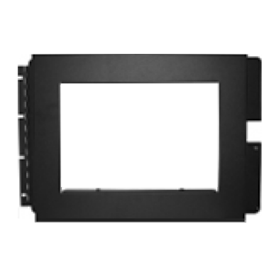
The model FHD2012-U1 Inner Door for Terminal Display Modules from Siemens Industry, Inc. is used
with the FHB2001-U1/R1 Backbox. The FHD2012-U1 Inner Door has an indentation and opening to allow
the FT2014 or FT2015 Remote Display Terminal to be installed in the FHB2001-U1/R1 Backbox in order
to meet the regulatory requirements for Canadian Applications. This inner door is black, and for indoor use
only in a dry and protected environment.
Figure 1: FHD2012-U1 Inner Door for the Remote Terminal Display Module
The following hardware kit is provided with FHD2012-U1:
Qty
4
Pan Philips semi-square screws
1
Ground Strap
Install the Remote Terminal Display Module on the Inner Door:
1. Separate the front panel from the back panel, making sure not to damage the ground strap "A".
The four screws will be reused, but disregard the back panel since it is no longer needed.
Siemens Industry, Inc.
Building Technologies Division
Florham Park, NJ
P/N A6V10385202_a_en_--
ITEM
Used to mount the inner door to the enclosure
Used to ground the inner door with the enclosure
USE
Advertisement
Table of Contents

Subscribe to Our Youtube Channel
Related Manuals for Siemens FHD2012-U1


Summary of Contents for Siemens FHD2012-U1
- Page 1 Inner Door for Remote Terminal Display Module INTRODUCTION The model FHD2012-U1 Inner Door for Terminal Display Modules from Siemens Industry, Inc. is used with the FHB2001-U1/R1 Backbox. The FHD2012-U1 Inner Door has an indentation and opening to allow the FT2014 or FT2015 Remote Display Terminal to be installed in the FHB2001-U1/R1 Backbox in order to meet the regulatory requirements for Canadian Applications.
- Page 2 3. Close the door and make certain that the spring-loaded fastener fits in the hole on the right side of the enclosure. Screw down the fastener to secure it in place. 4. Place one more #8-32 x 5/16” screw in the top hole and tighten all four screws securely. Figure 3: FHD2012-U1 in FHD2001-U1 with FT2014 P/N A6V10385202_a_en_--...
- Page 3 2. Install ground strap “C” between the two nuts “D” located on the enclosure. Figure 4: Installing the Ground Straps COMPATIBILITY FHD2012-U1 is an inner door that can be used with the FHB2001-U1/R1 backbox only. TECHNICAL DATA FHD2012-U1: 20-3/8”W x 2-1/4”D x 13-1/4”L...
- Page 4 This page was left intentionally blank. P/N A6V10385202_a_en_-- P/N A5Q00054386...
Need help?
Do you have a question about the FHD2012-U1 and is the answer not in the manual?
Questions and answers