Wolf CSO24 Service Manual
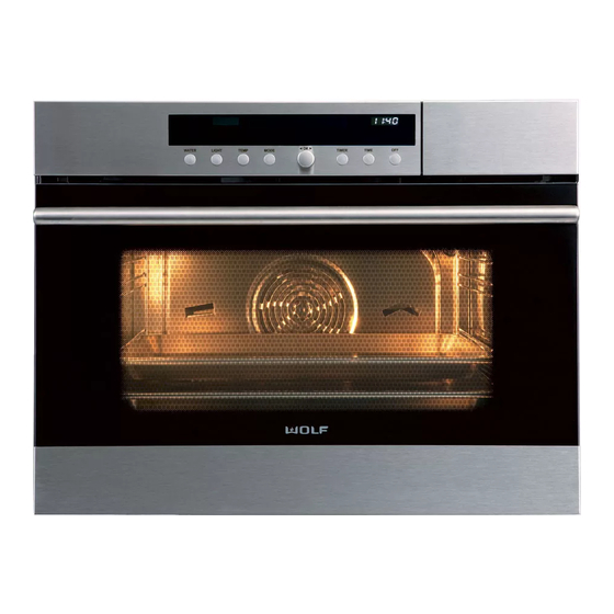
Convection steam oven
Hide thumbs
Also See for CSO24:
- Installation manual (16 pages) ,
- Installation information (5 pages) ,
- Installation information (9 pages)
Advertisement
Quick Links
Download this manual
See also:
Installation Manual
General Information
Installation Information
Controls & Operation
Component Access & Removal
Troubleshooting Guide
Technical Data
Wiring Diagrams
Convection Steam Oven
Service Manual
subzero.com
800.222.7820
10
22
33
43
44
2
5
Advertisement

Related Manuals for Wolf CSO24


Summary of Contents for Wolf CSO24
- Page 1 subzero.com 800.222.7820 Convection Steam Oven Service Manual General Information Installation Information Controls & Operation Component Access & Removal Troubleshooting Guide Technical Data Wiring Diagrams...
- Page 2 CSO24 and CSO30 (SWS #13508346) INTRODUCTION This Manual is a compilation of information from Wolf Inc. and V-ZUG Ltd., meant to provide the most recent techni- cal service information about model CSO24 and CSO30 starting with serial (SWS) #13508346. This information will enable the service technician to perform necessary repairs and return the appliance to proper operational condition.
- Page 3 CSO24 and CSO30 (SWS #13508346) WARRANTY INFORMATION This page contains a summary of the 2 & 5 Year Warranty that is supplied with every Wolf product, followed by a Non Residential Warranty Summary and then notes about the warranties. TWO & FIVE YEAR Warranty Summary •...
- Page 4 General Information CSO24 and CSO30 (SWS #13508346) CONVECTION STEAM OVEN FEATURES • Stainless steel with tubular handle. • Can be installed in a standard or flush inset application. • Stainless steel trim to match M series and E series ovens. • Convection with twelve cooking modes: steam, reheat, auto steam bake, convection, convection humid, convec- tion steam, gourmet, slow roast, recipes, my recipes, keep warm, descale and cleanse.
- Page 5 General Information CSO24 and CSO30 (SWS #13508346) DISPLAY AND CONTROL PANEL The display and control panel is streamlined and easy to use. The control knob and buttons are used to set the cooking modes and access all of the features of your convection steam oven for exceptional results.
- Page 6 This section of the manual covers some of the installation issues that a service technician may need to know when servicing a Wolf convection steam oven. If additional installation information is needed after reviewing this section of the manual please refer to the installation guide or contact the Wolf Appliance Customer Service Department.
- Page 7 Installation Information CSO24 and CSO30 (SWS #13508346) Electrical Requirements NOTES: • Electrical supply for the convection steam oven must be placed in an adjacent cabinet within 3' (914 mm) of the opening. Choose the electrical location shown in the illustrations on the following pages that best suits the instal- lation.
- Page 8 OPENING HEIGHT SIDE VIEW FRONT VIEW Notes: • Opening Width for CSO24 and CSO30 are the same. • Minimum base support 100 lbs (45 kg). • Electrical Supply must be located in adjacent cabinet with 3’ (914) of opening •...
- Page 9 Installation Information CSO24 and CSO30 (SWS #13508346) Flush Inset Installation TOP VIEW 23" (584) min FLUSH INSET 1" (25) DEPTH SIDE CLEATS FLUSH INSET WIDTH " TOP CLEAT " (460) min FLUSH INSET HEIGHT " BOTTOM CLEAT SIDE VIEW FRONT VIEW...
-
Page 10: Installing The Oven
Installation Information CSO24 and CSO30 (SWS #13508346) INSTALLING THE OVEN NOTE: Before moving the oven, protect any finished flooring and cabinetry to avoid damage. 1. Move the convection steam oven into position near the installation opening. Remove and discard packing mate- rials. - Page 11 THEORY OF OPERATION The Wolf convection steam oven has been developed for the highest levels of quality and ease of use. For best results the user should take a moment to become familiar with the oven’s composition, components, accessories and operation.
- Page 12 Theory of Operation CSO24 and CSO30 (SWS #13508346) Selecting and Changing Operating Modes Selecting Operating Mode 1. Press the MODE button until the desired mode appears. 2. Press the control knob to confirm the mode. Example: a. Press the MODE button until you reach auto steam bake mode. “Auto Steam Bake—Rack 2 or 1+3” appears in the text display.
- Page 13 Timer and Timer Functions The Wolf convection steam oven includes timer functions that manage cooking start and stop times so you can be away from the kitchen and still enjoy hot-from-the-oven meals at pre-specified times. Please take a moment to set your local time, and learn more about these useful time saving features.
- Page 14 Theory of Operation CSO24 and CSO30 (SWS #13508346) Delayed Start The delayed start feature automatically turns the convection steam oven both on and off at desired times. The instructions below assume food has been placed in the cooking space and a mode and temperature has been selected.
- Page 15 Theory of Operation CSO24 and CSO30 (SWS #13508346) Using the Temperature Probe The probe monitors food temperature and announces when it has reached a temperature considered “done” and safe for consumption. Using the probe also helps to maintain ideal tenderness. The internal temperatures shown in the chart below are the USDA recommendations for safe food consumption and desired doneness may vary.
- Page 16 Theory of Operation CSO24 and CSO30 (SWS #13508346) Checking and Changing Probe Temperature The TEMP button toggles between displaying the actual probe temperature and the set temperature. 1. To change the set probe temperature, press the TEMP button twice until the display reads “Probe Temperature”, then turn the control knob to set a new temperature and press to select.
- Page 17 Theory of Operation CSO24 and CSO30 (SWS #13508346) COOKING MODES Cooking Modes MODE USES Twelve cooking modes bring the world of modern food preparation right into the kitchen. Steam mode perfectly Steam Function Use the steam function for foods you poaches fish.
- Page 18 Theory of Operation CSO24 and CSO30 (SWS #13508346) Auto Steam Bake Bake just like a professional with auto steam bake mode. By heating with steam first, then using convection heat to finish baking, bagels, breads, buns, rolls and pastries acquire a tender interior, a beautiful exterior and a natural shine without the need for brushing with an egg wash.
- Page 19 Theory of Operation CSO24 and CSO30 (SWS #13508346) Recipes Mode Use the recipes mode for an easy and fun way to cook entire meals from appetizers and entrees to desserts. The recipes are listed by code in the chart below.
- Page 20 Theory of Operation CSO24 and CSO30 (SWS #13508346) Special Modes Demo Modus (Showroom Mode) Requirements: In order to switch the Demo Modus (Showroom Mode) ON / OFF, the appliance must be ready for operation, i.e. all displays - with the exception of the time display – should be dark/off.
- Page 21 Theory of Operation CSO24 and CSO30 (SWS #13508346) WATER LIGHT TEMP MODE TIMER TIME Figure 3-5. Exit Mode Configuration Demo-Modus WATER LIGHT TEMP MODE TIMER TIME Figure 3-6. Switch Demo Modus back On - Press and Hold LIGHT + OK + OFF (in that order)
- Page 22 Theory of Operation CSO24 and CSO30 (SWS #13508346) Diagnostic Mode This mode shows only error history and different time information. All error codes will appear on the display when they are happening to the appliance without entering diagnostic mode. Requirements: In order to turn the diagnostic mode on / off, the appliance must be in the OFF mode (all displays - with the exception of the time display - should be dark) or in the error mode (error message is dis- played).
- Page 23 COMPONENT ACCESS AND REMOVAL This section explains how to access and remove components in a CSO24 and CSO30 unit. An attempt has been made to arrange these procedures in such a way as to simulate which components would need to be removed first in order to gain access to other components.
- Page 24 Component Access CSO24 and CSO30 (SWS #13508346) Door Removal To remove the door (See Figure 4-1): 1. Open door fully. 2. Flip hinge retaining clips at each hinge up and back until they hit the stop knobs. 3. Move door in the closing direction until it stops against the tops of hinge retaining clips.
- Page 25 Component Removal CSO24 and CSO30 (SWS #13508346) Door Liner Glass Removal To remove the door liner glass (See Figures 4-4 and 4- 1. With door removed, lay it on a flat surface with the Door handle side up. Glass i n e r A s...
- Page 26 Component Access CSO24 and CSO30 (SWS #13508346) Light Bulb Removal Light Frame Light Bulb To remove a light bulb, first remove the left side rack guide, then (See Figure 4-7): 1. Extract screws securing oven light frame to left side wall.
- Page 27 Component Removal CSO24 and CSO30 (SWS #13508346) Hot Air (Convection) Heating Element Removal To remove the hot air heating element, first remove the Cap Nuts left and right side rack guides and the hot air cover, then (See Figure 4-10): 1.
- Page 28 Component Access CSO24 and CSO30 (SWS #13508346) Display Panel Control Board Removal (REAR VIEW) To remove the display control board, the top and back panel will need to be removed first, then (See Figure 4-13): Disconnect all electrical leads from display panel con- trol board.
- Page 29 Component Removal CSO24 and CSO30 (SWS #13508346) Exhaust Fan Assembly Removal To remove the exhaust fan assembly, first remove the Fan Assembly top and back panel, then (See Figure 4-16): 1. Disconnect electrical leads from fan motor. 2. Grasp fan motor and spin assembly clockwise until it stops, then lift assembly from hole in top of exhaust duct.
- Page 30 Component Access CSO24 and CSO30 (SWS #13508346) Climate (Exhaust) Temperature Sensor Removal To remove the climate temperature sensor, the top and back panel will need to be removed first, then (See Figure 4-19): Mounting 1. Disconnect sensor’s electrical leads from main con-...
- Page 31 Component Removal CSO24 and CSO30 (SWS #13508346) Cooking Space (Cavity) Temperature Sensor Temperature Sensor To remove the cooking space temperature sensor, the top and back panel will need to be removed first, then (See Figure 4-22): 1. Disconnect sensor’s electrical leads from main con- trol board at the back of appliance.
- Page 32 Component Access CSO24 and CSO30 (SWS #13508346) Boiler Assembly / Combi-Steam Removal To remove the boiler assembly, the top and back panel will need to be removed first, then (See Figure 4-25): Retaining Tab 1. Disconnect all electrical leads from boiler assembly.
- Page 33 Component Removal CSO24 and CSO30 (SWS #13508346) Food Probe Socket Assembly Probe Assembly Door To remove the food probe socket assembly, the top and (inside cooking space) back panel will need to be removed first, then (See Figure 4-28): 1. Using a tin-snips or similar tool cut the metal bridge at the four corners of the perforated probe socket cover.
- Page 34 Troubleshooting Guides CSO24 and CSO30 (SWS #13508346) TROUBLESHOOTING This section of the manual is divided into five troubleshooting guides and categories (see table of contents below). Table of Contents 1. Malfunctions with Error Codes .......................... 5-3 2. Malfunctions/Messages Without Error Codes ....................5-9 3.
- Page 35 CSO24 and CSO30 (SWS #13508346) Troubleshooting Guides Error Diagnostic Of Error Possible Cause Message Code (Through Microcontroller) (Ranked by Frequency) EEPROM 1. Problems with processor, caused by moisture or EMC influ- Read error (after 50 tries) ences. EEPROM 1. Problems with processor, caused by moisture or EMC influ- Write error (after 10 tries) ences.
- Page 36 Troubleshooting Guides CSO24 and CSO30 (SWS #13508346) Error Diagnostic Of Error Possible Cause Message Code (Through Microcontroller) (Ranked by Frequency) Food temperature 1. Break or loose contact in food probe or in its wiring. Food probe with too high of a resistance (temp.
- Page 37 CSO24 and CSO30 (SWS #13508346) Troubleshooting Guides Error Diagnostic Of Error Possible Cause Message Code (Through Microcontroller) (Ranked by Frequency) Control unit 1. Control unit faulty. temperature Sensor with too high of a resistance (temp. < ca. 3°F/-16°C) Control unit 1. Niche temperature too high (caused by second appliance?).
- Page 38 Troubleshooting Guides CSO24 and CSO30 (SWS #13508346) Error Diagnostic Of Error Possible Cause Message Code (Through Microcontroller) (Ranked by Frequency) Mains connection 1. No pole conductor connected to L2 clamp. L2 no signal 2. Circuit breaker or fuse in house wiring system activated.
- Page 39 CSO24 and CSO30 (SWS #13508346) Troubleshooting Guides Error Diagnostic Of Error Possible Cause Message Code (Through Microcontroller) (Ranked by Frequency) Water system 1. Boiler scaled up. If descaling was carried 2. Inlet valve leaking (valve not tight, limescale fragments in seal, out recently: etc.)
- Page 40 Troubleshooting Guides CSO24 and CSO30 (SWS #13508346) Error Diagnostic Of Error Possible Cause Message Code (Through Microcontroller) (Ranked by Frequency) Exhaust air slide valve 1. Exhaust slide valve stuck with grease deposits. Path of slide valve 2. Motor or slide valve jammed (mechanical defect).
- Page 41 CSO24 and CSO30 (SWS #13508346) Troubleshooting Guides Malfunctions/Messages Without Error Codes Possible Cause Display Text (Ranked by Frequency) Insert water tank 1. Water tank is missing. 2. Water tank not in end position or faulty. 3. Mechanical lock damaged or missing.
- Page 42 Troubleshooting Guides CSO24 and CSO30 (SWS #13508346) 3. Malfunctions Without Fault Displays//Messages Possible Cause Malfunction (Ranked by Frequency) Heating element(s) not heating up. 1. Heating element(s) or the corresponding wiring is faulty. 2. Demo-Modus is activated. From time to time, strange (illegible) 1.
-
Page 43: Menu Structure
CSO24 and CSO30 (SWS #13508346) Troubleshooting Guides Diagnostic Mode This mode shows only error history and different time information. If the appliance has an error, that error code will appear on the display when it is happening to the appliance without entering diagnostic mode. - Page 44 Technical Data CSO24 and CSO30 (SWS #13508346) CSO24 and CSO30 TECHNICAL DATA DESCRIPTION WATTS (W) AMPS (A) RESISTANCE (Ohms) Heater, Hot Air 2070 Heater, Bottom Heater, Boiler 1500 Fan, Hot Air 1236 Boiler, Drain Pump 1202 Fan, Cool Air 0.05...
- Page 45 Wiring Diagrams CSO24 and CSO30 (SWS #13508346) #9001333 - Revision A - August, 2014...
Need help?
Do you have a question about the CSO24 and is the answer not in the manual?
Questions and answers