Table of Contents
Advertisement
Quick Links
S&C 6801M Automatic Switch Operators
Reciprocating and Rotating Switch Operation
Table of Contents
Section
Qualified Persons . . . . . . . . . . . . . . . . . . . . . . . . . . 2
Read this Instruction Sheet . . . . . . . . . . . . . . . . . . . 2
Retain this Instruction Sheet. . . . . . . . . . . . . . . . . . . 2
Proper Application . . . . . . . . . . . . . . . . . . . . . . . . . . 2
Special Warranty Provisions . . . . . . . . . . . . . . . . . . . 2
Understanding Safety-Alert Messages . . . . . . . . . . . 4
Following Safety Instructions . . . . . . . . . . . . . . . . . . 4
Replacement Instructions and Labels . . . . . . . . . . . 4
. . . . . . . . . . . . . . . . . . . . . . . . . . . 5
Applicable Software . . . . . . . . . . . . . . . . . . . . . . . . . 6
Pre-Installation Inspection and Setup. . . . . . . . . . . . 7
Installation . . . . . . . . . . . . . . . . . . . . . . . . . . . . . . . . .11
Adding Ac Power . . . . . . . . . . . . . . . . . . . . . . . . . . .19
Setting Switch Travel . . . . . . . . . . . . . . . . . . . . . . . .19
The latest 6801M Automatic Switch Operator instruction sheets are posted as PDF files at sandc.com/
en/support/product-literature/. 6801M software (all revisions) can be downloaded at sandc.com/
en/support/sc-customer-portal/. If requiring assistance, please contact sandc.com/en/support
/technical-support/ or call our 24/7 support center at (888) 762-1100.
September 4, 2018
© S&C Electric Company 2007-2018, all rights reserved
Installation
Page
Section
Setting Travel Limits . . . . . . . . . . . . . . . . . . . . . . . . 22
Testing Switch Operation . . . . . . . . . . . . . . . . . . . . 23
Service . . . . . . . . . . . . . . . . . . . . . . . . . . . . . . . . 24
Load Resistor . . . . . . . . . . . . . . . . . . . . . . . . . . . 24
Installing the Switch Operator and Connecting
the Wiring . . . . . . . . . . . . . . . . . . . . . . . . . . . . . . 26
Adding Ac Power . . . . . . . . . . . . . . . . . . . . . . . . . . 35
Setting Travel Limits . . . . . . . . . . . . . . . . . . . . . . . . 35
Testing Switch Operation . . . . . . . . . . . . . . . . . . . . 36
Service . . . . . . . . . . . . . . . . . . . . . . . . . . . . . . . . 37
NOTICE
. . . . . . . . . . . . . . . . . . . . . . 38
. . . . . . . . . . . . . . . . . 40
Instruction Sheet 1045M-510
Page
Advertisement
Table of Contents

Related Manuals for S&C 6801M


Summary of Contents for S&C 6801M
-
Page 1: Table Of Contents
Setting Switch Travel ......19 NOTICE The latest 6801M Automatic Switch Operator instruction sheets are posted as PDF files at sandc.com/ en/support/product-literature/. 6801M software (all revisions) can be downloaded at sandc.com/ en/support/sc-customer-portal/. -
Page 2: Introduction
PDF format at sandc.com/en/ support/product-literature/. Retain this This instruction sheet is a permanent part of your S&C 6801M Automatic Switch Operator. Designate a location where you can easily retrieve and refer to this publication. Instruction Sheet... - Page 3 IntelliTeam® SG Automatic Restoration System until the desired result is achieved. Warranty of the S&C 6801M Automatic Switch Operator is contingent upon the installation, configuration, and use of the control or software in accordance with S&C’s applicable instruction sheets.
-
Page 4: Safety Information
Safety Information Understanding Several types of safety-alert messages may appear throughout this instruction sheet and on labels attached to the S&C 6801M Automatic Switch Operators. Familiarize yourself Safety-Alert with these types of messages and the importance of these various signal words:... -
Page 5: Safety Precautions
Safety Precautions DANGER The S&C 6801M Automatic Switch Operator line voltage input range is 93 to 276 Vac. Failure to observe the precautions below will result in serious personal injury or death. Some of these precautions may differ from your company’s operating procedures and rules. -
Page 6: Before Switch Operator Installation
General>Revisions screen. For questions regarding the applicability of information in this instruction sheet to future software releases, please contact S&C Electric Company. Although the 6801M Switch Operator will work acceptably with most distribution switches, be sure to check with S&C Electric Company before using the switch operator with any switch not on the list of switches on the Setup>General>Switch Operator screen. -
Page 7: Pre-Installation Inspection And Setup
There is risk of SERIOUS injury if these precautions are not observed. NOTICE Operating a switch with a 6801M Automatic Switch Operator may result in a reduction of its fault-closing rating. The fault-closing ratings for S&C switches applied with a 6801M Automatic Switch Operators can be found in the following publications: •... - Page 8 STEP 3. Check the batteries. The 6801M Switch Operator is shipped with two C&D Technologies UPS12-150MR 12-volt batteries (or other approved batteries). Check with S&C Electric Company before using batteries of a type or capacity other than those supplied.
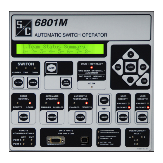
- Page 9 (g) Use the insulated jumper to connect the remaining (–) negative terminal (black) on one battery to the remaining (+) positive terminal (red) on the other. Figure 2. The 6801M Switch Operator faceplate (shown for the 6801M Switch Operator with the IntelliTeam SG software option).
- Page 10 The setup software can also diagnose certain types of switch operator hardware problems. Review the “Computer Requirements” section in Instruction Sheet 1045M- 530, “S&C 6801M Automatic Switch Operators: Setup” for details, and install the latest software on the computer. STEP 7.
-
Page 11: Installing The Rotating Switch Operator
Use insulated tools to tighten/loosen the battery connections, and turn off the 24-volt circuit breaker before installing or removing the batteries. The 6801M Switch Operator is capable of generating tremendous torque and speed. Make sure the 24-volt dc circuit breaker is off before putting your hands or other body parts near the actuator shaft. - Page 12 Installing the Rotating Switch Operator CAUTION Failure to properly install pipe couplings with piercing set screws can cause slip- page of the operating pipe, resulting in improper operation of the switch, arcing, equipment damage, or electrical shock. To properly install piercing set screws: (a) Back the piercing set screw out of the coupling so the tip does not protrude into the space for the pipe.
- Page 13 Installing the Rotating Switch Operator dations to be used along with locally accepted practices. If the switch operator is not pole-mounted, procedure details may vary. Mount the switch operator (see Figure 9 on page 16) to the pole (see Figure 10 on page 17) with ⅝-inch or ¾-inch through-bolts and flat washers as follows: (a) Install the top bolt.
- Page 14 Installing the Rotating Switch Operator Figure 4. The universal joint showing the 1/4-inch (6-mm) gap for the top pipe. Note: Do not tighten the piercing set screw to the operator pipe until instructed in the “Setting Switch Travel” section on page 19.
- Page 15 Installing the Rotating Switch Operator Figure 6. The fully pierced set screw does not need to be flush with the bracket. Figure 7. The piercing set screw for the switch operator output shaft is the last to tighten. S&C Instruction Sheet 1045M-510...
- Page 16 Installing the Rotating Switch Operator Figure 8. The universal joint clamp at the first section of pipe. 1 29/32 (48) Ø 3 11/16 (94) (1 1/2 IPS PIPE) Ø 1.500 (38) 1 11/16 (43) SINGLE POINT LIFT BRACKET Ø 13/16 (21) MOUNTING HOLES 2 1/8 (54)
- Page 17 Installing the Rotating Switch Operator DOUBLE-COIL LOCK WASHER 30 (762) (RECOMMENDED FOR WOOD POLES) 18 1/2 (470) Figure 10. The side view of the rotating switch operator enclosure on pole, dimensions are inches (mm). SLOT IN TOP OF SHROUD PERMITS INSTALLATION WITHOUT DISCONNECTING THE CONTROL ROLD...
- Page 18 Installing the Rotating Switch Operator NOTICE The switch operator is designed to minimize problems caused by minor variation in operator-switch geometry due to age and environmental effects. However, if it is not securely fastened to the pole, excessive movement of the switch operator can result in incomplete switch operation and potentially serious damage to the switch mechanism.
-
Page 19: Adding Ac Power
(The Battery Charger/Control I/O board is on the left side of the enclosure.) If any of these LEDs do not illuminate, see Instruction Sheet 1045M-550, “S&C 6801M Automatic Switch Operators: Troubleshooting.” Setting Switch Travel DANGER The following procedure requires that the switch be fully bypassed or de-energized. - Page 20 Installing the Rotating Switch Operator Use the manual handle to place the switch in the Closed position. Note the STEP 3. direction of rotation. A rotating switch operator is factory set to operate clockwise from closed to open as viewed from above. Operation can be configured to operate counterclockwise when the switch requires it.
- Page 21 Installing the Rotating Switch Operator ALIGNED HOLES IN PADLOCKING TAB CENTRAL AND LOCKING PLATE HOLE Figure 14. Align the holes for padlocking (top view, rotating operator). S&C Instruction Sheet 1045M-510...
-
Page 22: Setting Travel Limits
Installing the Rotating Switch Operator Setting Travel Limits If the travel limits have not been set, the CLOSED LED will blink. Follow these steps to set the travel limits: STEP 1. The switch should be in the Closed position. If it is not closed, decouple the switch operator from the switch (see Step 2 on page 19), and manually close he switch. -
Page 23: Testing Switch Operation
NOT READY LED to turn on. To clear the flag, briefly toggle the ENABLE/DISABLE switch. If the ERROR DETECTED or NOT READY LED is still on or if the CLOSE/OPEN LEDs do not operate as described, see Instruction Sheet 1045M-550, “S&C 6801M Automatic Switch Operators: Troubleshooting.” Testing Switch... -
Page 24: Putting The Switch Into Local/Non-Automatic
Automatic Operation in the Disabled state (not Enabled state) until the software in the switch operator is configured for this installation. This completes the rotating switch operator hardware installation. See Instruction Sheet 1045M-530, “S&C 6801M Automatic Switch Operators: Setup” for instructions about configuring the switch operator. Adjusting the The factory-set, spiral-wound load resistor is used both as a battery-test load and a current- limiting (torque-limiting) resistor for setting the closed-reference torque. - Page 25 Installing the Rotating Switch Operator If the Closed Torque setpoint is not modified, the torque after a normal Close opera- tion equals the reference value. If a higher value is selected for the Closed Torque set- point, the switch operator adjusts the final Closed position, based on the overall spring constant, to obtain the desired closed torque.
-
Page 26: Installing The Reciprocating Switch Operator
Installing the Reciprocating Switch Operator Installing the Switch The switch operator installation consists of several operations. The following information is specific to the 6801M Reciprocating Switch Operator. Operator and Connecting the Wiring STEP 1. Read, and make sure to understand, the following functional description and safety instructions before beginning to install or operate this equipment. - Page 27 Use insulated tools to tighten/loosen the battery connections, and turn off the 24-volt circuit breaker before installing or removing the batteries. The 6801M Switch Operator is capable of generating tremendous torque and speed. Make sure the 24-volt dc circuit breaker is off before putting your hands or other body parts near the actuator shaft.
- Page 28 Installing the Reciprocating Switch Operator Figure 15. The side view of reciprocating switch operator showing mounting bolts through pole. (b) The correct length for each ⅝-inch bolt will be the diameter of the pole at the point of insertion plus 3¼ inches (83 mm). Check the pole diameter at the location of each hole and select a bolt of the correct length before beginning the installation.
- Page 29 Hole# 5 from the hinge point, next to the outermost hole. The switch operator should also be configured to apply 200 ft-lbs of closing torque on the operating rod. See Instruction Sheet 1045M-530, “S&C 6801M Automatic Switch Operators: Setup” for more information.
- Page 30 Installing the Reciprocating Switch Operator NOTICE For information on other manufacturer’s switches and specific rating, please contact S&C Electric Company. 3 feet (914) maximum Switch 4 feet (1219) maximum Operating Rod Guides 4 feet (1219) maximum 3 feet (914) Operating maximum Switch Operator...
- Page 31 Installing the Reciprocating Switch Operator 4 X DRAIN SENSOR COMMUNICATIONS CONNECTIONS CONNECTOR (WHEN ORDERED) (WHEN ORDERED) Ø 1 3/8 (35) ENTRY FOR INCOMING POWER CONNECTIONS 6 (152) 2 3/4 GROUND LUG (70) #14 - #2 AWG TEMPERATURE 2 1/8 (54) SENSOR 14 1/2 (368)
- Page 32 Installing the Reciprocating Switch Operator Figure 20. Position linkage as shown to center the operating rod on the pole. Use the manual handle to close the switch by lifting the crank arm upward. STEP 9. (a) Open the operating mechanism shroud, if installed (see Figure 21). Attach the manual operating handle (see Figure 22 on page 33), and rotate the output crank upward until the switch is firmly closed.
- Page 33 Installing the Reciprocating Switch Operator VERTICAL OPERATING PIPE / ROD 1 ¼ IPS THREADED CLEVIS (CONNECTS OUTPUT CRANK MOUNTING CHANNEL TO VERTICAL OPERATING PIPE / ROD) DECOUPLING MECHANISM MANUAL OPERATING HANDLE (FULL LENGTH OF HANDLE IS NOT SHOWN) LOCKOUT BRACKET (FOR MANUAL OPERATION ONLY) OUTPUT...
- Page 34 Installing the Reciprocating Switch Operator CAUTION Proper operation of the switch requires that all of the blades move in unison and that all blades contact their mating surfaces simultaneously during operation. Failure to make proper contact can result in switch failure. Figure 24.
-
Page 35: Adding Ac Power
LEDs should illuminate. The Battery Charger/Control I/O board is on the left side of the enclosure. If any of these LEDs does not illuminate, see Instruction Sheet 1045M-550, “S&C 6801M Automatic Switch Operator: Troubleshooting.” Setting Travel Limits DANGER The following procedure requires that the switch be fully bypassed or de-energized. -
Page 36: Testing Switch Operation
If the ERROR DETECTED or NOT READY LED is still on or if the CLOSE/OPEN LED does not operate as described, see Instruction Sheet 1045M-550, “S&C 6801M Automatic Switch Operators: Troubleshooting.” Testing Switch Follow these steps to test the switch operation: Operation STEP 1. -
Page 37: Putting The Switch Into Local/Non-Automatic
AUTOMATIC OPERATION in Disabled state (not Enabled state) until the software in the switch operator is set up for this installation. This completes the reciprocating switch operator hardware installation. See Instruction Sheet 1045M-530, “S&C 6801M Automatic Switch Operators: Setup” for information about configuring the switch operator. S&C Instruction Sheet 1045M-510... -
Page 38: Installation And Connection Drawings
Installation and Connection Drawings Rotating Switch Operator DRAWING NO. CDR-10039 S&C Instruction Sheet 1045M-510... - Page 39 Installation and Connection Drawings Rotating Switch Operator—continued DRAWING NO. CDR-10039 S&C Instruction Sheet 1045M-510...
-
Page 40: Reciprocating Switch Operator
Installation and Connection Drawings Reciprocating Switch Operator CDR-10042 S&C Instruction Sheet 1045M-510... - Page 41 Installation and Connection Drawings Reciprocating Switch Operator—continued CDR-10042 S&C Instruction Sheet 1045M-510...
Need help?
Do you have a question about the 6801M and is the answer not in the manual?
Questions and answers