Table of Contents
Advertisement
Quick Links
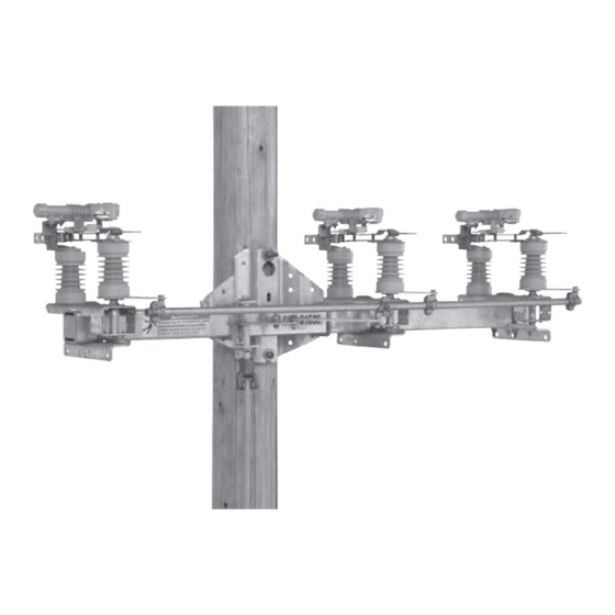
S&C Omni-Rupter
®
Outdoor Distribution
14.4 kV and 25 kV
Table of Contents
Section
Operating Considerations . . . . . . . . . . . . . . . . . . . . . . . . 2
Qualified Persons . . . . . . . . . . . . . . . . . . . . . . . . . . . . . . 2
Read this Instruction Sheet . . . . . . . . . . . . . . . . . . . . . . 3
Retain this Instruction Sheet . . . . . . . . . . . . . . . . . . . . . . 3
Proper Application . . . . . . . . . . . . . . . . . . . . . . . . . . . . . 3
Warranty . . . . . . . . . . . . . . . . . . . . . . . . . . . . . . . . . . . . . 3
Understanding Safety-Alert Messages . . . . . . . . . . . . . . 4
Following Safety Instructions . . . . . . . . . . . . . . . . . . . . . 4
Replacement Instructions and Labels . . . . . . . . . . . . . . . 4
Location of Safety Labels . . . . . . . . . . . . . . . . . . . . . . . 5
. . . . . . . . . . . . . . . . . . . . . . . . . . . . .6
n
For installation instructions for Omni-Rupter Switches with Catalog Number Supplement "R4," please refer to your local S&C Sales Office . These
instructions are also available on www.sandc.com.
August 8, 2011© S&C Electric Company
Switches
Three-Pole Side-Break Integer Style
Upright and Triangular Mounting Configurations
Catalog Number Supplement "R3" and Earlier
Installation
Page
Section
Packing . . . . . . . . . . . . . . . . . . . . . . . . . . . . . . . . . . . . . . 7
Inspection . . . . . . . . . . . . . . . . . . . . . . . . . . . . . . . . . . . . 7
Installation
Operating Pipe Preparation . . . . . . . . . . . . . . . . . . . . . . 8
Mounting to Wood . . . . . . . . . . . . . . . . . . . . . . . . . . . . . . 8
Mounting the Switch Upright . . . . . . . . . . . . . . . . . . . . . . 8
Mounting the Switch Triangular . . . . . . . . . . . . . . . . . . . 10
Installing the Optional Pole Band . . . . . . . . . . . . . . . . . 10
Installing the Vertical Operating Pipe . . . . . . . . . . . . . . 11
Installing the Operating Handle . . . . . . . . . . . . . . . . . . 13
Installing the Wildlife Protection Option . . . . . . . . . . . . 15
Dead-Ending Conductors . . . . . . . . . . . . . . . . . . . . . . . 19
Connecting High-Voltage Conductors . . . . . . . . . . . . . . 19
Locking the Operating Handle . . . . . . . . . . . . . . . . . . . 21
Checking Operation . . . . . . . . . . . . . . . . . . . . . . . . . . . 23
Instruction Sheet 765-500
n
Page
Advertisement
Table of Contents

Subscribe to Our Youtube Channel
Related Manuals for S&C Omni-Rupter


Summary of Contents for S&C Omni-Rupter
-
Page 1: Table Of Contents
Checking Operation . . . . . . . . . . . . . . . . . . . . . . . . . . . 23 For installation instructions for Omni-Rupter Switches with Catalog Number Supplement “R4,” please refer to your local S&C Sales Office . These instructions are also available on www.sandc.com. -
Page 2: Introduction
Introduction Operating Ç CAUTION Considerations The equipment covered by this publication must be selected for a specific applica- tion and it must be installed, operated, and maintained by qualified persons who are thoroughly trained and who understand any hazards that may be involved. This publication is written only for such qualified persons and is not intended to be a substitute for adequate training and experience in safety procedures for this type of equipment. -
Page 3: Read This Instruction Sheet
The standard warranty contained in S&C’s standard conditions of sale, as set forth in Price Sheet 150, is applicable to the S&C Omni-Rupter Switch covered in this instruction sheet except when it is power operated using a switch operator of other than S&C manufacture. -
Page 4: Safety Information
Understanding There are several types of safety-alert messages which may appear throughout this instruc- tion sheet as well as on labels and tags attached to the Omni-Rupter Switch. Familiarize Safety-Alert Messages yourself with these types of messages and the importance of the various signal words, as explained below. -
Page 5: Location Of Safety Labels
Safety Information Location of Safety Labels REORDER INFORMATION FOR SAFETy LABELS Location Safety Alert Message Description Number Switches may be energized from either side and with blades in Ç DANGER G-6580-1 any position . Switches may be energized from either side and with blades in Ç... -
Page 6: Safety Precautions
Safety Precautions Ç DANGER Omni-Rupter Switches operate at high voltage. Failure to observe the precautions below will result in serious personal injury or death. Some of these precautions may differ from company operating procedures and rules. Where a discrepancy exists, users should follow their company’s operating procedures and rules. -
Page 7: Packing And Inspection
“-V1,” “-V2,” or “-V3”—adds (one, two, or three respectively) extra 610 lengths of pipe and includes the appropriate number of extra couplings and guides. 6. A detailed erection drawing (ED) for the Omni-Rupter will be found in a water- resistant envelope shipped with the switch. If a Standard Mounting Arrangement is to be used, this erection drawing is a printed sheet. -
Page 8: Operating Pipe Preparation
Installation Operating Pipe Preparation If desired, the vertical operating pipe can be cut to length (if not precut at the factory) before proceeding to the job site. The standard lengths of pipe supplied measure 6-10. Cutting dimen- sions are shown on the erection drawing. Mounting to Wood When mounting the switch and its operating mechanism to a wood pole, it is recommended... - Page 9 (remove and discard after switch is mounted) open slotted-hole for ease of installation.) Figure 1. Hoisting upright mounting configuration Omni-Rupter switch g. Lower the switch so that the pole-saddle into position. bears down on the through bolts.
-
Page 10: Mounting The Switch Triangular
Make sure that the switch is fully closed. b. Attach lifting slings ONLY to the vertical switch support member by looping around Figure 2. Hoisting Omni-Rupter switch into position for triangular mount- the dead-ending bracket and the switch ing configuration. -
Page 11: Installing The Vertical Operating Pipe
Installation If desired, a crossarm brace (user-furnished) may be attached to the base for switches in the upright mounting configuration. Mounting brackets for crossarm braces must be specified separately. Consult your nearest S&C Sales Office for details. Installing the Vertical Operating Pipe Step 5 S&C recommends making up each coupling as work progresses. - Page 12 Installation Step 7 Install a universal coupling on the lower end Uppermost pipe of the uppermost section of vertical operating section pipe in the fashion described above, using the ¹⁄₂—13 2¹⁄₂ bolt and ¹⁄₂—13 nut provided. See Figure 6. bolts (2) ¹⁄₂...
-
Page 13: Installing The Operating Handle
Installation Installing the Operating Handle Grounding strap Step 11 a Install the operating-handle assembly on the Vertical-operating-pipe lowest section of vertical operating pipe at the section location indicated on the erection drawing. Make certain the cutting tip of the piercing set Piercing set screw screw in the operating-handle assembly does not protrude through the clamp when install-... - Page 14 Installation Step 14 Ç CAUTION Adjust the stop plates to remove all excess play from the operating mechanism and to attain proper “windup” tension before ener- gizing the switch. Slack in the operating pipe may allow the switch to creep out of the fully-closed Adjustable stop plates position.
-
Page 15: Installing The Wildlife Protection Option
• One fiberglass interphase operating rod, pre-installed. Wildlife disks Pole-saddle cover Wildlife disks Base cover Base cover Fiberglass interphase operating rod Wildlife disks Figure 10. 14.4-kV Omni-Rupter with Optional Wildlife Protection (Catalog Number Suffix “-W”), Upright Mounting Configuration. S&C Instruction Sheet 765-500... - Page 16 Installation NOTICE Base cover S&C recommends installing the wildlife Switch base protection option after the switch is secured to the utility pole. Damage to the wildlife option may occur if lifting slings strain the wildlife disks dur- ing handling. In Figure 10 on page 15, a typical installation of the wildlife protection option is illustrated.
- Page 17 On 25-kV Omni-Rupter Switches (Porcelain and Cypoxy® Insulators) Blade-end of the switch: Install the wildlife disk Figure 13. Wildlife disk placement on 14.4-kV Omni-Rupter Switches. on the bottom skirt root of the insulator. Contact-end of the switch: Count up two skirts from the base and install the wildlife disk to the insulator on the blade-end.
- Page 18 Installation Step 18 a. To assemble the disks, fit the disk around the insulator on the blade-end of the switch. See Figure 15. Then, insert the locking tabs of one-half of the disk into the open slot on Insulator the other half to create a secure overlapping fit.
-
Page 19: Dead-Ending Conductors
Installation Dead-Ending Conductors Dead-ending provisions are standard on Omni-Rupter switches that have upright, upright (extra mounting pole clearance), or triangular, mounting configurations. When dead-ending to these brackets, a pole band and extension-link assemblies are required. See Figure 18. Line conductor Maximum dead-end loading for S&C dead-... - Page 20 Installation Step 19 The Omni-Rupter terminal pads are silver plated and do not require abrasive cleaning as a part of their preparation. Wipe any dirt or grease from the surface, and apply a thick coating of Penetrox A or other appropriate conductor ®...
-
Page 21: Locking The Operating Handle
Installation Locking the Operating Handle Step 21 With padlock: The operating-handle assembly includes swing-away hasps for padlocking the interrupter switch in either the open or closed position. With key interlock: The interlock group (see Figure 20) includes a Superior key interlock, Type B6003-1 Mk II single or multiple key (or equivalent), with ³⁄₈-inch bolt projection and ³⁄₄-inch bolt travel, locking disc, and interlock... - Page 22 Installation b. Install the operating-handle assembly on the lowest section of vertical operating pipe at the location indicated in the erection drawing. Make certain the cutting tip of the piercing set screw in the operating-handle assembly does not protrude when installing the assembly on the vertical operating pipe.
-
Page 23: Checking Operation
Installation Checking Operation Step 23 Open and close the interrupter switch by swing- ing the handle slowly through its full travel. Check to be sure that the following conditions exist: a. With the operating handle as far as it will go in the closing direction, all main contacts Blade of the interrupter switch are in the fully-... - Page 24 Installation a. Open and close the switch and examine the View A, During Closing interrupter and blade alignment. The inter- rupter must be parallel to the sweep of the blade. Main contact b. Partially open the switch. The following min . ¹⁄₆₄...
- Page 25 Installation e. Slowly open the switch. As the blade moves in the opening direction, the blade shunt contact must firmly engage the interrupter housing contact before the blade disengages from the jaw contact. Bend and reform the shunt contact if necessary to attain the proper contact.
- Page 26 Installation Step 25 View A, During Closing For 25 kV switches. Check the following on each phase. Main contact a. Examine the interrupter and blade align- ment. The interrupter must be parallel to the min . ¹⁄₆₄ sweep of the blade. Opening lever b.
- Page 27 Installation e. Slowly open the switch. As the blade moves in the opening direction, the blade shunt contact must firmly engage the interrupter housing contact before the blade disengages from the jaw contact. Bend and reform the shunt contact if necessary to attain the proper contact.
Need help?
Do you have a question about the Omni-Rupter and is the answer not in the manual?
Questions and answers