Table of Contents
Advertisement
Omni-Rupter
®
Switch
Outdoor Distribution
(14.4 kV through 34.5 kV)
Table of Contents
Section
Qualified Persons . . . . . . . . . . . . . . . . . . . . . . . . . . 2
Operating Considerations . . . . . . . . . . . . . . . . . . . . . 2
Read this Instruction Sheet . . . . . . . . . . . . . . . . . . . 2
Retain this Instruction Sheet. . . . . . . . . . . . . . . . . . . 2
Proper Application . . . . . . . . . . . . . . . . . . . . . . . . . . 3
Warranty . . . . . . . . . . . . . . . . . . . . . . . . . . . . . . . . . . 3
Understanding Safety-Alert Messages . . . . . . . . . . . 4
Following Safety Instructions . . . . . . . . . . . . . . . . . . 4
Replacement Instructions and Labels . . . . . . . . . . . 4
Location of Safety Labels . . . . . . . . . . . . . . . . . . . . . 5
. . . . . . . . . . . . . . . . . . . . . . . . . 6
Packing . . . . . . . . . . . . . . . . . . . . . . . . . . . . . . . . . . . 7
Inspection . . . . . . . . . . . . . . . . . . . . . . . . . . . . . . . . . 7
Handling . . . . . . . . . . . . . . . . . . . . . . . . . . . . . . . . . . 8
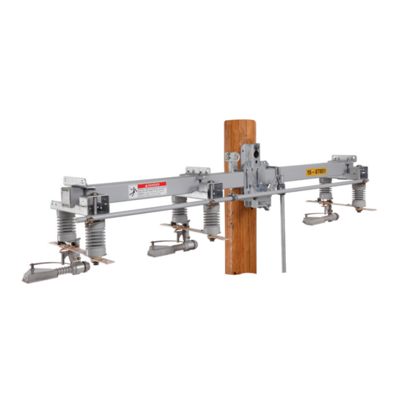
Upright Mounting Configuration
October 26, 2020
© S&C Electric Company 2011-2020, all rights reserved
Three-Pole Side-Break Integer Style
Rotating Operating Mechanism
Upright, Upright Extra Mounting Clearance, Triangular, and
Inverted Mounting Configurations
Installation and Operation
Page
Triangular Mounting Configuration
Section
Operating Pipe Preparation . . . . . . . . . . . . . . . . . . . 9
Mounting to Wood . . . . . . . . . . . . . . . . . . . . . . . . . . . 9
Mounting the Switch Assembly. . . . . . . . . . . . . . . . .10
Installing the Optional Pole Band . . . . . . . . . . . . . . .13
Installing the Vertical Operating Pipe . . . . . . . . . . .14
Installing the Operating Handle . . . . . . . . . . . . . . . .16
Wildlife Protection . . . . . . . . . . . . . . . . . . . . . . . .18
Installing the Base Covers . . . . . . . . . . . . . . . . . . . .19
Installing the Wildlife Disks . . . . . . . . . . . . . . . . . . 20
Dead-Ending Conductors . . . . . . . . . . . . . . . . . . . . 24
Connecting High-Voltage Conductors . . . . . . . . . . 24
Locking the Operating Handle . . . . . . . . . . . . . . . . 26
Checking Operation . . . . . . . . . . . . . . . . . . . . . . . . 28
To Open . . . . . . . . . . . . . . . . . . . . . . . . . . . . . . . . . .31
To Close . . . . . . . . . . . . . . . . . . . . . . . . . . . . . . . . . .31
Inverted Mounting Configuration
Instruction Sheet 765-510
Page
Advertisement
Table of Contents

Related Manuals for S&C Omni-Rupter Series


Summary of Contents for S&C Omni-Rupter Series
-
Page 1: Table Of Contents
Omni-Rupter ® Switch Three-Pole Side-Break Integer Style Outdoor Distribution Rotating Operating Mechanism (14.4 kV through 34.5 kV) Upright, Upright Extra Mounting Clearance, Triangular, and Inverted Mounting Configurations Installation and Operation Table of Contents Section Page Section Page Introduction Installation Qualified Persons ......2 Operating Pipe Preparation . -
Page 2: Introduction
Introduction Qualified Persons WARNING Only qualified persons who are knowledgeable in the installation, operation, and maintenance of overhead and underground electric distribution equipment, along with all associated hazards, may install, operate, and maintain the equipment covered by this publication. A qualified person is someone who is trained and competent in: •... -
Page 3: Proper Application
Introduction Proper Application WARNING The equipment in this publication is only intended for a specific (application or applications). The application must be within the ratings furnished for the equipment. Ratings for the Omni-Rupter Switch are listed in the ratings table in Specification Bulletin 765-31. -
Page 4: Safety Information
Safety Information Understanding Several types of safety-alert messages may appear throughout this instruction sheet and on labels and tags attached to your Omni-Rupter Switch. Familiarize yourself with these Safety-Alert types of messages and the importance of these various signal words: Messages DANGER “DANGER”... -
Page 5: Location Of Safety Labels
Safety Information Location of Safety Labels Reorder Information for Safety Labels Location Safety Alert Message Description Number DANGER Switches may be energized from either side and with blades in any position. G-6580-2● WARNING Lifting Instructions G-9377■ WARNING Lifting Instructions G-9379■ NOTICE Instructions for Connecting Conductors to Terminal Pads G-9391■... -
Page 6: Safety Precautions
Safety Precautions DANGER Omni-Rupter Switches operate at high voltage. Failure to observe these precautions will result in serious personal injury or death. Some of these precautions may differ from company operating procedures and rules. Where a discrepancy exists, users should follow their company’s operating procedures and rules. -
Page 7: Shipping And Handling
Shipping and Handling Packing Drawings for standard mounting arrangements show only minimum or suggested locating dimensions for the Study the erection drawing carefully and check the bill of vertical-operating-pipe guide bearings and the operating- materials to make sure all listed parts are at hand. handle assembly. -
Page 8: Handling
Shipping and Handling Handling Crate WARNING DO NOT use the lifting bracket to lift the crated switch from the truck or conveyance. The lifting bracket will only hold the weight of the switch and will NOT hold the weight of the crated switch and associated packing materials. -
Page 9: Installation
Installation Operating Pipe Preparation If desired, the vertical operating pipe can be cut to length (if not precut at the factory) before proceeding to the job site. The standard lengths of pipe supplied measure 6 feet 10 inches (208 cm). Cutting dimensions are shown on the erection drawing. -
Page 10: Mounting The Switch Assembly
Installation Mounting the Switch Assembly (j) If desired, a crossarm brace (user-furnished) may be attached to the base. Mounting Upright Mounting Configurations brackets for crossarm braces must be specifi ed separately. Contact your local S&C WARNING Sales Offi ce for details. Lift the switch using the lifting bracket provided. - Page 11 Installation Inverted Mounting Configuration WARNING Lift the switch using the lifting bracket provided. Do Lag screws (2) not allow lifting slings to stress switch parts. Avoid opposite screw allowing the switch to swing while lifting. Key hole not shown not shown Lifting the switch by the base or mounting bracket may cause damage to the switch.
- Page 12 Installation Triangular Mounting Configuration WARNING Lift the switch by the attaching lifting slings to the vertical switch support member by looping around Lifting slings the dead-ending bracket and the switch mounting weldment. Do not allow lifting slings to stress switch parts.
-
Page 13: Installing The Optional Pole Band
Installation Installing the Optional Pole Band ½-inch lag Through-bolt STEP 4. Secure the pole-band (optional) to the mounting screw ● bracket on the switch, using the J-bolts provided. See Figure 6. Two ¼ × 1 × 3-inch stiffening Pole mounting blocks are furnished to be used behind the pole- bracket band fl anges and underneath the J-bolt nuts. -
Page 14: Installing The Vertical Operating Pipe
Installation Installing the Vertical Operating Pipe S&C recommends assembling each coupling as work progresses from the top down, starting with the univer- sal coupling connecting the switch to the upper section of vertical operating pipe. Continue with the universal coupling between the upper section of vertical operating pipe and the fi rst lower section, the splice couplings con- necting the lower sections of pipe to each other, and end with the rotating operating handle or 6801M Automatic... - Page 15 Installation STEP 6. Install a universal coupling on the lower end of the uppermost section of the vertical operating Uppermost pipe section pipe in the fashion described above using the ½ × 13 × 2½-inch bolt and ½—13 nut provided. See Figure 9. STEP 7.
-
Page 16: Installing The Operating Handle
Installation Installing the Operating Handle Grounding strap NOTICE Vertical operating pipe section If ordered with provisions for power operation with the 6801M Automatic Switch Operator (catalog number suffix “-M”), omit steps 10 through 13 and proceed Piercing set screw with the installation steps described in the 6801M Swing-away hasps for Operator Installation Instructions (S&C Instruction padlocking... - Page 17 Installation STEP 12. Open and close the interrupter switch slowly to Fully close the switch and apply sufficient check that no operating diffi culties are pressure to the handle in the closing direction encountered caused by undetected damage in to remove all play in the operating-pipe linkage. shipping.
-
Page 18: Installing The Optional Phase-To-Ground Wildlife Protection
Installation Installing the Optional Phase-to-Ground Wildlife Protection Wildlife disks (Catalog Number Suffix “-W”) DANGER De-energize the switch and ground it at all six terminals before installing the wildlife protection option. The Wildlife Protection option is not designed to be installed on energized equipment. Base cover Failure to do so could lead to serious injury or death. -
Page 19: Installing The Base Covers
Installation Installing the Base Covers Base cover Base covers are only used on switches in the upright Switch base mounting confi guration. Skip to “Installing the Wildlife Disks” section on page 20 for switches in the inverted mounting confi guration. With the switch in the Closed position, place STEP 15. -
Page 20: Installing The Wildlife Disks
Installation Installing the Wildlife Disks Before installing the wildlife disks, determine the proper placement of the disks on the switch blade and contact insulators. Contact end Blade end On Upright 14.4-kV Omni-Rupter Switches Disks overlap (Porcelain and Cypoxy™ Insulators) blade-end over Install the wildlife disk to the bottom skirt root of the Insulator Insulator... - Page 21 Installation On Inverted 14.4-kV Omni-Rupter Switches (Porcelain and Cypoxy Insulators) Install the wildlife disk to the lowest skirt of the insulator on both the blade and contact ends of the switch. When Rotating the wildlife disks are installed properly, the disks will insulator slightly overlap, as shown in Figure 19.
- Page 22 Installation STEP 17. Upright mounting confi guration shown; inverted mounting confi guration similar. For Insulator Disk halves installation on 34.5-kV Omni-Rupter Switches, refer to the separate installation instructions provided with the wildlife disks. (a) To assemble the disks, fi t the disk around the insulator on the blade end of the switch.
- Page 23 Installation (b) Starting with the outside locking tabs fi rst, squeeze the overlapping sides together until the tabs audibly snap into place. (c) Push the two halves of the disk together in toward the insulator so the disk fi ts the Push disk halves insulator as close as possible.
-
Page 24: Dead-Ending Conductors
Installation Dead-Ending Conductors Dead-ending provisions are standard on Omni-Rupter Switches in the upright, upright with extra mounting pole clearance, triangular, or inverted mounting confi gurations. When dead-ending to these brackets, a pole band and extension-link assemblies are required. See Figure 25. ●... - Page 25 Installation The Omni-Rupter Switch terminal pads are silver-plated and do not require abrasive cleaning as a part of their preparation. Wipe any dirt or grease from the surface and apply a thick coating of Burndy Corporation’s Penetrox® A or other appropriate conductor preparation compound. Terminal pad NOTICE Blade...
-
Page 26: Locking The Operating Handle
Installation Locking the Operating Handle Interlock (with ⅜-inch bolt Vertical operating NOTICE projection and pipe ¾-inch bolt travel) If ordered with provisions for power operation with the 6801M Automatic Switch Operator (catalog Locking number suffix “-M”), omit Step 20 and proceed with disc ⅜-inch the locking instructions described in the 6801M... - Page 27 Installation (b) Install the operating-handle assembly on the lowest section of vertical operating pipe at the location indicated in the erection drawing. Make sure the cutting tip of the piercing set screw in the operating-handle assembly does not protrude when installing the assembly on the vertical operating pipe.
-
Page 28: Checking Operation
Installation Checking Operation NOTICE Blade If furnished with provisions for power operation using the 6801M Automatic Switch Operator (catalog number suffix “-M”), perform Steps 21 and 22 using the installed 6801M operator and the instructions Guide fingers described in the "Adjusting the Tap Position on the Load Resistor"... - Page 29 Installation Check the following on each phase. STEP 22. Interrupter Interrupter (a) Open and close the switch and examine the interrupter and blade alignment. The interrupter and interrupter shunt arm must be parallel to the sweep of the blade. See Figure 33.
- Page 30 Installation • The blade should move into the jaw contact guide fingers center. Figure 36. • When the switch is fully closed, the inter- rupter shunt arms are no more than -inch ⅛ (3 mm) from the auxiliary return arms of the multipurpose operating cams, and the shunt arms and return arms do not touch.
-
Page 31: Operation
Operation WARNING Operating DO NOT operate the Omni-Rupter Switch slowly handle or part way by using a “chopping” motion. When in service, the Omni-Rupter Switch should always be opened or closed vigorously through its full travel without hesitation at any point to avoid arcing and personal injury.
Need help?
Do you have a question about the Omni-Rupter Series and is the answer not in the manual?
Questions and answers