Table of Contents
Advertisement
Quick Links
Advertisement
Table of Contents

Subscribe to Our Youtube Channel
Related Manuals for Sierra Wireless mangOH Green DV4


Summary of Contents for Sierra Wireless mangOH Green DV4
- Page 1 mangOH™ Green (DV4) User Guide 4118902 Rev 3 Contents subject to change...
- Page 2 The Sierra Wireless modem can transmit signals that could interfere with this equipment. Do not operate the Sierra Wireless modem in any aircraft, whether the aircraft is on the ground or in flight. In aircraft, the Sierra Wireless modem MUST BE POWERED OFF.
- Page 3 Preface Patents This document contains information which is proprietary to Sierra Wireless Inc. and is licensed pursuant to Creative Commons Attribution 4.0 International License. Document Title: mangOH Green User Guide details Author: Sierra Wireless Source: http://mangoh.io/ Copyright © 2016 Sierra Wireless. Licensed under the Creative Commons Attribution 4.0 license, http://creativecommons.org/licenses/by/4.0/...
-
Page 4: Table Of Contents
Contents Introduction ............. . . 6 mangOH Green Components and Accessories. - Page 5 Contents Software Setup ............38 Install / Update Windows Driver.
-
Page 6: Introduction
Once you have the mangOH Green set up, visit mangoh.io for developer documentation, code samples, and other materials. Important: This User Guide applies to mangOH Green DV4. The guide for mangOH Green DV3 is available at mangoh.io. mangOH Green Components and Accessories Table 1-1 details the required and optional components needed to begin using the mangOH Green in your development environment. - Page 7 Introduction Table 1-1: mangOH Green Components (Continued) Item Details Micro-USB cable Connects computer to the mangOH Green for communication and to provide power for non-transmitting tests. • Power supply Output voltage: 4.5V to 17V • 10 W or higher • The mangOH Green will operate with USB power, but DC power may be required to make and establish a full-speed mobile network connection.
- Page 8 mangOH Green (DV4) User Guide Table 1-1: mangOH Green Components (Continued) Item Details Ethernet cable Ethernet cable (Cat5 or better) for use with the mangOH Green’s 100 Mbps Ethernet connector RS-232 DB9 cable Serial cable used for console output (male connector required on mangOH end) Battery Rechargeable Li-Ion or Li-Polymer battery (3V7 nominal) for use...
- Page 9 Introduction Table 1-2: mangOH-compatible CF3 Modules Series Notes The mangOH schematic (available at mangoh.io), describes all interfaces that are supported by the mangOH Green. The following table identifies signals that (as of publication date of this document) are currently not supported on WP85xx/WP75xx-series modules. Refer to http://source.sierrawireless.com for current Product Technical...
-
Page 10: Setup And Installation
2: Setup and Installation Safe Handling Recommendations To help prevent accidental damage to the mangOH Green: • Use safe ESD-handling practices (such as wearing proper ESD straps) to avoid possible ESD damage. • Avoid touching the CF3 module sockets (J200, J601). These pins can be damaged if they catch on clothing or other materials. -
Page 11: Initial Setup
Setup and Installation Initial Setup To begin using the mangOH Green, set up your hardware and software: 1. Insert a suitable CF3 module in the primary socket. See Insert/Remove Embedded Modules on page 12. Select Primary Power Supply. See page 16. 3. -
Page 12: Hardware Setup And Operation
3: Hardware Setup and Operation This chapter describes how to install various components on the mangOH Green, and how to configure and control features using connectors and switches. Insert/Remove Embedded Modules The mangOH Green has two CF3 module sockets • Primary (J200)—The primary module includes a wireless modem and application processor. - Page 13 Hardware Setup and Operation 2. Hold the module above the socket and line up the polarity marks on the module and socket. (Primary module installation shown.) Figure 3-2: CF3 Module Positioning 3. Place the module onto the socket. The module should drop into place when you have it aligned properly.
- Page 14 mangOH Green (DV4) User Guide 4. Attach the module cover: a. Hold the module cover above the CF3 module and line up the polarity marks on the module and cover. Figure 3-4: Installing Module Cover b. Place the cover on the module, then press down carefully until you hear the cover click into place.
-
Page 15: Power Supply
Hardware Setup and Operation Figure 3-6: Removing the Module Cover 3. Lift the cover off the module. 4. Carefully pinch the module and pull it straight up out of the socket. Power Supply The mangOH Green has the following supplies: Table 3-1: mangOH Green Power Supplies Supply Details... -
Page 16: Select Primary Power Supply
mangOH Green (DV4) User Guide Select Primary Power Supply To select the primary power supply: 1. Place the mangOH Green face-up and locate the power supply jumper pins (CN1204). 1—Power supply select (CN1204) 2—DC jack 3—micro-USB connector (bottom side of board) Figure 3-7: Power Supply Select (CN1204) 2. -
Page 17: Connect Battery Backup
Hardware Setup and Operation Connect Battery Backup Optionally, you can connect a rechargeable Li-Ion/Li-Polymer battery to the mangOH Green to provide uninterrupted power in the event that the primary power supply (DC or USB) fails. If a jumper is placed on CN1201, the mangOH Green recharges the battery and then provides a trickle charge to maintain the battery’s full charge. -
Page 18: Rtc Capacitor
mangOH Green (DV4) User Guide Caution: The board is designed to use a rechargeable Li-Ion or Li-polymer battery. Regular (non-rechargeable) batteries are NOT recommended. However, if a regular battery is used, DO NOT place a jumper on CN1203 as this will damage the battery and possibly the board. RTC Capacitor The mangOH Green provides a capacitor that maintains the RTC. - Page 19 Hardware Setup and Operation To establish a mobile network connection with a UMTS/LTE CF3 module, you must install at least one SIM card: • Live card(s) with active accounts, or • Test card(s) for use with a call box (for example, an Agilent 8960 or Rohde &...
- Page 20 mangOH Green (DV4) User Guide Figure 3-13: SIMs—Inserting Figure 3-14: SIMs—Inserted Rev 3 Nov.16 4118902...
-
Page 21: Insert Microsd Card
Hardware Setup and Operation Insert microSD Card The mangOH Green includes a microSD card slot in the top part of CN802. To install a microSD card: 1. Place the Dev Kit face-down (as shown). 1—mini-SIM (CN801) 2—micro-SIM (CN802—bottom) 3—micro-SD (CN802—top) Figure 3-15: SIM Connector and micro-SD Locations 2. -
Page 22: Connect Antenna(S)
mangOH Green (DV4) User Guide Figure 3-17: microSD—Inserted Connect Antenna(s) The mangOH Green includes three antenna ports for the primary CF3 module. Table 3-3: Antenna Ports Type Connector Details Main CN307 Required to establish a mobile network data connection Diversity CN304 Used only if primary CF3 supports diversity. - Page 23 Hardware Setup and Operation 1—Main (CN307) 2—GNSS (CN306) 3—Diversity (CN304) Figure 3-18: Antenna Connector Locations 2. Attach the antenna cable’s female connector to the board’s male connector and press firmly to get a secure connection. (Note that female connectors are rated for a limited number of reconnects before the connector wears out, so should be left connected if possible.
-
Page 24: Insert/Remove Iot Expansion Cards
mangOH Green (DV4) User Guide Insert/Remove IoT Expansion Cards The mangOH Green includes three single-width IoT Expansion Card slots. If the board uses IoT Expansion Card mounting rails and you want to use a double- width (2-slot) or triple-width (3-slot) expansion card, remove the rails between the slots you will be using. - Page 25 Hardware Setup and Operation Figure 3-21: IoT Expansion Card Inserted To remove an IoT Expansion Card: 1. Pull the expansion card straight out, using safe ESD-handling practices (such as wearing proper ESD straps). For detailed interface information for each IoT Expansion Card slot, refer to the mangOH Green Developer’s Guide.
-
Page 26: Arduino-Compatible Circuit
mangOH Green (DV4) User Guide Arduino-compatible Circuit The mangOH Green includes an integrated Arduino-compatible circuit (with connector for use with Arduino-compatible shields, and an Atmega32U4 microcontroller). 1—Arduino-compatible headers 2—mini-USB connector Figure 3-22: Integrated Arduino-compatible Circuit The Arduino-compatible circuit is controlled directly via a mini-USB cable connection from your computer. -
Page 27: Connect Arduino-Compatible Shield
Hardware Setup and Operation Connect Arduino-compatible Shield To connect an Arduino-compatible shield to the mangOH Green: 1. Position the shield above the headers. (Note that the two rows of headers have different numbers of pins—make sure to position the shield correctly.) 1—18-pin header 2—14-pin header Figure 3-24: Arduino-compatible Shield Example... -
Page 28: Audio Connection
mangOH Green (DV4) User Guide 1—ICSP pins fully seated 2—Shield pins fully seated 3—mini-USB connection for direct control from computer Figure 3-26: Arduino-compatible Shield Installed on mangOH Green Audio Connection The mangOH Green includes a 3.5 mm audio jack for use with audio-enabled CF3 modules. -
Page 29: Ethernet Connection
Hardware Setup and Operation Ethernet Connection The mangOH Green includes a 100 Mbps Ethernet port that may be used to connect the board to a LAN. 1—Ethernet port (100 Mbps) Figure 3-28: Ethernet Port The Ethernet port has two LEDs that exhibit the behavior described in Table 3-4. -
Page 30: Usb Host Connection
mangOH Green (DV4) User Guide USB Host Connection The mangOH Green includes a USB Host port (USB 2.0) for attaching a peripheral device, memory stick, etc. 1—USB Host port Figure 3-30: USB Host Port RS-232 Console Output Connection The mangOH Green includes an RS-232 DB9 connector for console output. By default, this port is enabled and configured to connect to the primary module’s UART2 (two-wire interface). -
Page 31: Led Indicators
Hardware Setup and Operation LED Indicators The mangOH Green includes several LED indicators. Table 3-5: mangOH Green LEDs Description On when power is supplied by any power source (USB, DC, 1—Power (VCC_3V7) battery) 2—Rx (Arduino- On when the Arduino-compatible circuit is receiving data compatible circuit) 3—AirVantage connected On when device is connected to AirVantage 4 —Tx (Arduino-... -
Page 32: Reset Switches
11 - WLAN connected 4 - Tx (Arduino-compatible circuit) 8 - Battery charging 12 - RF disabled (W_DISABLE_N) Figure 3-32: LED Indicators (mangOH Green DV4 Configuration) Reset Switches The mangOH Green includes two reset switches: • Board reset (SW400)—Press and hold for 5 seconds to reset the board (including... -
Page 33: Mangoh Green Configuration
Hardware Setup and Operation 1—Board reset (SW400) 2—Arduino-compatible circuit reset (SW1500) Figure 3-33: Reset Switches mangOH Green Configuration Default Configuration The mangOH Green‘s default configuration is described in Table 3-6. Table 3-6: mangOH Green Default Configuration Component / Switch Default Configuration / Behavior Notes SMA connectors can be added, if required, by a Antenna connectors... -
Page 34: Switch And Jumper Configuration Options
mangOH Green (DV4) User Guide Table 3-6: mangOH Green Default Configuration (Continued) Component / Switch Default Configuration / Behavior Notes Board can be configured using a software SD connector Connected to primary module command to connect primary module’s SDIO (CN802) signals to IOT1 instead of SD connector. - Page 35 Hardware Setup and Operation Table 3-9: SW401—Module Signals Control Signal On / Off State Enable POWER_ON signal for primary On (Default) module (J200) POWER_ON Disable POWER_ON signal MDM_Power Reserved for future use Off (Default) Disable RF power for primary CF3 module W_DISABLE_N Off (Default) Enable RF power for primary CF3 module...
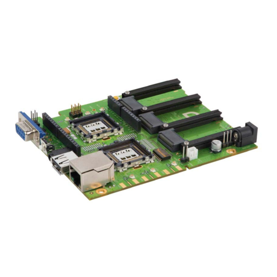
- Page 36 mangOH Green (DV4) User Guide 1 - IoT Expansion Card slot #2 2 - IoT Expansion Card slot #1 3 - IoT Expansion Card slot #0 4 - DC power (CN1200) 5 - Power supply select (CN1204) 6 - Battery connector (CN1202) 7 - Recharge select (CN1203) 8 - Signals control (SW401) 9 - Main antenna...
- Page 37 Hardware Setup and Operation 1 - USB power 2 - micro-SIM (bottom slot) 3 - microSD (top slot) 4 - mini-SIM 5 - Arduino-compatible circuit mini-USB 6 - ATmega32U4 Figure 3-35: mangOH Green Assembly - Bottom Side Switches/Connectors Note: For reference only. For latest schematic, visit mangoh.io. Rev 3 Nov.16 4118902...
- Page 38 Figure 4-1: Windows Device Manager If the driver installed correctly, you will see the following items listed: • Modems > Sierra Wireless WWAN Modem (This is the module in socket J200.) • Ports [COM & LPT] > Sierra Wireless DM Port Rev 3 Nov.16...
- Page 39 Software Setup • Ports [COM & LPT] > Sierra Wireless NMEA Port (This is the port that you will use to communicate with the module from your terminal emulator.) Install a Terminal Emulator To communicate with the mangOH Green, you need to use a terminal emulator ®...
Need help?
Do you have a question about the mangOH Green DV4 and is the answer not in the manual?
Questions and answers