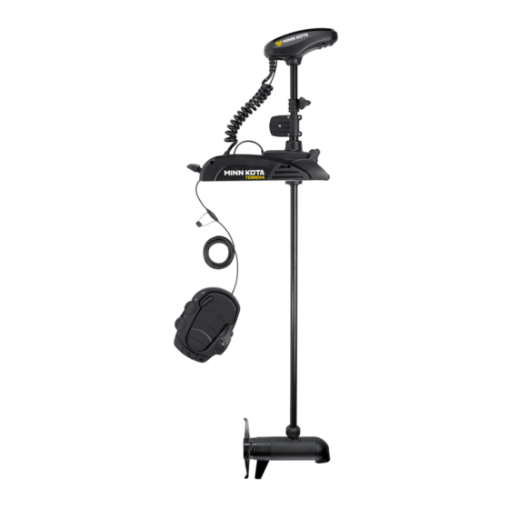
MINN KOTA TERROVA Owner's Manual
Bow-mount trolling motor
Hide thumbs
Also See for TERROVA:
- Installation instructions manual (49 pages) ,
- User manual (23 pages) ,
- Owner's manual (116 pages)
Table of Contents
Advertisement
Advertisement
Table of Contents
Troubleshooting

Related Manuals for MINN KOTA TERROVA


Summary of Contents for MINN KOTA TERROVA
- Page 1 TERROVA BOW-MOUNT TROLLING MOTOR Owner's Manual...
- Page 2 THANK YOU Thank you for choosing Minn Kota. We believe that you should spend more time fishing and less time positioning your boat. That’s why we build the smartest, toughest, most intuitive trolling motors on the water. Every aspect of a Minn Kota trolling motor is thought out and rethought until it’s good enough to bear our name.
-
Page 3: Table Of Contents
WARRANTY ........................5 KNOW YOUR BOAT ......................6 FEATURES ........................7 INSTALLATION ......................... 8 Installing the Terrova ....................9 Identifying Trolling Motor Features by Their Associated Cables ........14 Routing Connection Cables ..................14 Feature overview and connecting the cables ..............16 BATTERY &... -
Page 4: Safety Considerations
WARNING You are responsible for the safe and prudent operation of your vessel. We have designed your Minn Kota product to be an accurate and reliable tool that will enhance boat operation and improve your ability to catch fish. This product does not relieve you from the responsibility for safe operation of your boat. -
Page 5: Warranty
Products purchased outside of the U.S. must be returned prepaid with proof of purchase (including the date of purchase and serial number) to any Authorized Minn Kota Service Center in the country of purchase. -
Page 6: Know Your Boat
KNOW YOUR bOaT Port Starboard Inboard Outboard Keel Port Starboard Gunwale Transom Stern Gunwale Stern Hull 6 | minnkotamotors.com ©2018 Johnson Outdoors Marine Electronics, Inc. -
Page 7: Features
feaTURes AutoPilot Push-to-Test Power Battery Meter Adjustable Depth Collar Power Button Depth Collar Knob Indicator Panel Lift Assist Housing Steering Housing Stow Deploy Lever Fall Away Ramps Low Profile Foot Pedal Lifetime Warranty Flexible Composite Shaft Lift Assist Collar Cool Quiet Power Motor Propeller... -
Page 8: Installation
INSTALLING THE TERROVA Your new Terrova comes with everything you’ll need to directly install it to the boat. This motor can be directly mounted to the boat or coupled with a Minn Kota quick release bracket for ease of mounting and removal. For installation with a quick release bracket, refer to the installation instructions provided with the bracket. -
Page 9: Installing The Terrova
INSTALLING THE TERROVA MOUNTING CONSIDERATIONS It is recommended that the motor be mounted as close to the centerline of the boat as possible. Make sure the area under the mounting location is clear to drill holes and install View accessories nuts and washers. - Page 10 INSTALLING THE TERROVA Remove the Right Sideplate. Swing the Left Sideplate out and away from the Base Extrusion. Base Extrusion Left Sideplate Right Sideplate Make sure that the Power Cables from the battery are disconnected, or that the breaker, Power Cables if equipped, is "off".
- Page 11 INSTALLING THE TERROVA ITEM(S) NEEDED #4 x 6 When the motor is in the deployed position, make sure that the Shaft is 1-1/2" out past the Gunwale of the boat. The lower unit, when stowed and deployed must not encounter any obstructions.
- Page 12 INSTALLING THE TERROVA ITEM(S) NEEDED #1 x 6 #3 x 6 #4 x 6 #2 x 6 Put a 1/4-20 x 2" (Item #1) screw in each of the Screw drilled locations. The screw should pass through the Base Extrusion and the boat deck. If the rubber washers (Item #4) are used, they should sit between the Base Extrusion and boat deck.
- Page 13 INSTALLING THE TERROVA Replace the four sideplate screws using a #3 or #2 Phillips screwdriver. Two of these screws will be located on each side of the mount. Sideplate Screw ITEM(S) NEEDED #18 x 5 #EE x 1 Take the Foot Pedal (Item #EE) and turn it over.
-
Page 14: Identifying Trolling Motor Features By Their Associated Cables
ROUTING UNIVERSAL SONAR & i-PILOT LINK CABLES IDENTIFYING TROLLING MOTOR FEATURES BY THEIR ASSOCIATED CABLES Your trolling motor may be pre-installed with Built-In MEGA Down Imaging OR Universal Sonar, and may include i-Pilot Link. All of these features require cables to be connected to an output device. These connections are present on the trolling motor and have cables that exit below the Control Head. - Page 15 ROUTING UNIVERSAL SONAR & i-PILOT LINK CABLES Place the motor in the deployed position. One Connection Control Head Built-in MEGA Down Imaging or Locate the Built-in MEGA Down Imaging, i-Pilot Link Universal Sonar and/or Universal Sonar cable(s), at the base of the Control Head.
-
Page 16: Feature Overview And Connecting The Cables
Built-In MEGA Down Imaging delivers nearly 3X the output of standard Side Imaging®, and takes fishfinding into the megahertz frequency for the very first time. The Minn Kota flagship families of trolling motors, including Ultrex, Ulterra, Terrova, and Fortrex, now include Built-In MEGA Down Imaging sonar, the clearest imaging available only from Humminbird. - Page 17 CONNECTING A UNIVERSAL SONAR EXTENSION CABLE When installing with a Solix, the Built-In MEGA Humminbird Solix Fish Finder Down Imaging cable can be plugged directly into the Solix fish finder. Plug the Built-in MEGA Down Imaging cable into the corresponding connection on the Solix fish finder.
- Page 18 CONNECTING A UNIVERSAL SONAR EXTENSION CABLE The Universal Sonar Cables are shielded to minimize interference. To protect this shielding the cables should not be pulled tight against sharp angles or hard objects. If using cable ties, do not over-tighten. Any excess cable should be bundled in a loose loop of no less than 4”...
- Page 19 Link i-Pilot Link allows your Minn Kota trolling motor and Humminbird to communicate with each other to change the way you fish. i-Pilot Link delivers a large array of GPS capabilities including controlling speed, steering, Spot-Lock, and the ability to record and retrace paths on the water, all at your fingertips.
- Page 20 Link will be paired with either Coil Built-in MEGA Down Imaging or Universal Sonar Cord on Ultrex, Ulterra or Terrova. i-Pilot Link is not a feature offered on Fortrex motors. NOTICE: Paired with a Universal Sonar connector for illustration purposes. A Built-in MEGA Down Mount Imaging connector may be present instead.
-
Page 21: Battery & Wiring Installation
CAUTION These guidelines apply to general rigging to support your Minn Kota motor. Powering multiple motors or additional electrical devices from the same power circuit may impact the recommended conductor gauge and circuit breaker size. If you are using wire longer than that provided with your unit, follow the conductor gauge and circuit breaker sizing table below. -
Page 22: Selecting The Correct Batteries
Review your charger’s manual carefully or consult the manufacturer prior to use to ensure your charger is compatible. Minn Kota recommends using Minn Kota brand chargers to recharge the batteries connected to your Minn Kota trolling motor, as they have been engineered to work with motors that include a bonding wire. -
Page 23: Connecting The Batteries
CONNECTING THE BATTERIES IN SERIES Automatic Jump Start Systems and Selector Switches Automatic jump start systems and selector switches tie the negatives of the connected batteries together. Connecting these systems to the “High Side” Battery or “Middle” Battery in the diagrams below and will cause significant damage to your trolling motor and electronics. The only trolling motor battery that is safe to connect to one of these systems is the “Low Side”... -
Page 24: Connecting The Batteries In A Series
CONNECTING THE BATTERIES IN SERIES CONNECTING THE BATTERIES IN SERIES (IF REQUIRED FOR YOUR MOTOR) 24 Volt Systems Two 12 volt batteries are required. The batteries must be wired in +24 Volts to trolling motor positive (or circuit breaker) series, only as directed in wiring diagram, to provide 24 volts. To trolling motor negative Make sure that the motor is switched off 24 Volt Series Connection... - Page 25 CONNECTING THE BATTERIES IN SERIES 36 Volt Systems Three 12 volt batteries are required. The batteries must be wired in series, only as directed in wiring diagram, to provide 36 volts. Make sure that the motor is switched +36 Volts to trolling motor off (speed selector on “0”).
-
Page 26: Motor Wiring Diagram
TERROVA The following Motor Wiring Diagram applies to all Terrova models that do not come factory installed i-Pilot or i-Pilot Link. Not all models come with Universal Sonar or Built-in MEGA Down Imaging. CoPilot can be installed on these models, but this feature may not come already installed from the factory. - Page 27 MOTOR WIRING DIAGRAM TERROVA WITH i-PILOT OR i-PILOT LINK The following Motor Wiring Diagram applies to all Terrova models that come factory installed with either i-Pilot or i-Pilot Link. i-Pilot Black M- Fuse Brown Black B- Ground Black M- Accessory...
-
Page 28: Using & Adjusting The Motor
Power Button The Power button is located on the Indicator Panel on the Mount. The Terrova must be manually powered "on" and "off". When the Motor is powered "on", the Power Indicator will be illuminated green . When the Motor is powered "off", the Power Indicator will not be illuminated 28 | minnkotamotors.com... -
Page 29: Stowing And Deploying The Motor
STOWING AND DEPLOYING THE MOTOR CAUTION For safety reasons, disconnect the motor from the battery/batteries when the motor is not in use or while the battery/batteries are being charged. If the motor control is left on and the propeller rotation is blocked, severe motor damage can result. AutoPilot The AutoPilot Indicator is located on the Indicator Panel on the Mount. -
Page 30: Adjusting The Depth Of The Motor
ADjUSTING THE DEPTH OF THE MOTOR MOTOR ADjUSTMENTS ADjUSTING THE DEPTH OF THE MOTOR Once the boat is on the water, it may be necessary to adjust the Lower Unit up or down to achieve an optimum depth for motor performance. -
Page 31: Adjusting The Lower Unit For A Secure Stow
ADjUSTING THE LOWER UNIT FOR A SECURE STOW ADjUSTING THE LOWER UNIT FOR A SECURE STOW When the Motor is stowed, the Lower Unit should rest on the Fall Away Ramps, a part of the Motor Mount. It is recommended to secure the motor using the following instructions to avoid damage to the motor and shaft from vibrations during transport. -
Page 32: Installing An External Transducer
INSTALLING AN EXTERNAL TRANSDUCER INSTALLING AN EXTERNAL TRANSDUCER An external transducer is not included with your trolling motor. An external transducer can be installed onto motors that have Universal Sonar or motors that do not have a built in transducer. For more information on Universal Sonar, please visit minnkotamotors.com. Installing an external transducer is not recommended for motors with Built-in MEGA Down Imaging. -
Page 33: Using The Foot Pedal
You must avoid hazards to navigation and always maintain a permanent watch so you can respond to situations as they develop. You must always be prepared to regain manual control of your boat. Learn to operate your Terrova in an area free from hazards and obstacles. - Page 34 USING THE FOOT PEDAL Steer Right/Steer Left CAUTION The Steer Right and Steer Left buttons are located at the The steering system is designed to turn your motor 360 bottom of the Foot Pedal. They function to steer right and left. degrees.
-
Page 35: Service & Maintenance
seRVICe & MaINTeNaNCe PROPELLER REPLACEMENT TOOLS AND RESOURCES REQUIRED • 9/16” Open End Wrench • Flat Blade Screwdriver INSTALLATION Disconnect the motor from all sources of power prior to changing the propeller. Drive Pin Armature Shaft Hold the propeller and loosen the Prop Nut with a pliers or a wrench. -
Page 36: General Maintenance
SERVICE & MAINTAINANCE GENERAL MAINTENANCE • After use, the entire motor should be rinsed with freshwater. This series of motors is not equipped for saltwater exposure. • The composite shaft requires periodic cleaning and lubrication for proper retraction and deployment. A coating of an aqueous based silicone spray will improve operation. -
Page 37: For Further Troubleshooting And Repair
Authorized Service Centers Minn Kota has over 800 authorized service providers in the United States and Canada where you can purchase parts or get your products repaired. Please visit our Authorized Service Center page on our website to locate a service provider in your area. -
Page 38: Compliance Statements
Minn Kota motors are not subject to the disposal regulations EAG-VO (electric devices directive) that implements the WEEE directive. Nevertheless never dispose of your Minn Kota motor in a garbage bin but at the proper place of collection of your local town council. - Page 39 FCC COMPLIANCE FCC COMPLIANCE This device complies with Part 15 of the FCC rules. Operation is subject to the following two conditions: This device may not cause harmful interference. This device must accept any interference that may be received, including interference that may cause undesired operation. Changes or modifi cations not expressly approved by Johnson Outdoors Marine Electronics, Inc.
-
Page 40: Parts Diagram & Parts List
55/80/112 LBS THRUST - 12/24/36 VOLT - 45”/54”/60”/72” SHAFT The parts diagram and parts list provides Minn Kota® WEEE compliance disassembly instructions. For more information about where you should dispose of your waste equipment for recycling and recovery and/or your European Union member state requirements, please contact your dealer or distributor from which your product was purchased. - Page 41 PARTS DIAGRAM & PARTS LIST Control Head Parts List Assembly Part # Description Quantity 2774176 MOTOR KIT, iPLT 1.6 TRV,UTX *I-PILOT RECEIVER* 2774177 MOTOR KIT, iPLT 3.0 TRV,UTX *I-PILOT LINK RECEIVER* Â 2994075 REMOTE ASSY, IPILOT 1.6 2994076 REMOTE ASSY, IPILOT LINK *I-PILOT LINK ONLY* Â...
- Page 42 PARTS DIAGRAM & PARTS LIST Item Part # Description Quantity 2325631 DECAL, COVER, TERROVA 55 *55LB THRUST* 2325632 DECAL, COVER, TERROVA 80 *80LB THRUST* 2394900 INSTRUCTION HEADING SENSOR 2325634 DECAL, PUSH BTN TOP, TRV/iP 112 2395554 DECAL, PUSH BTN TOP, T2/iP 80...
- Page 43 PARTS DIAGRAM & PARTS LIST TERROVA MOTOR 12 Volt 3.626" Motor Parts Diagram minnkotamotors.com | 43 ©2018 Johnson Outdoors Marine Electronics, Inc.
- Page 44 PARTS DIAGRAM & PARTS LIST 12 Volt 3.626" Motor Parts List Assembly Part # Description Quantity 2779032 Ì MTR/TUBE ASM 55# 45" TRV/US2 BT *45* *3.625* *UNIVERSAL SONAR* 2779024 MTR/TUBE ASM 55# 54" TRV BT *54* *3.625* 2779033 Ì MTR/TUBE ASM 55# 54" TRV/US2 BT *54* *3.625* *UNIVERSAL SONAR* 1378131 PROP IND 2091160 WDLS WDG II *3.625* *55LB THRUST* 2888460...
- Page 45 PARTS DIAGRAM & PARTS LIST Item Part # Description Quantity 788-015 RETAINING RING *3.625* 140-010 BREARING 2-100-146 ARM ASY 12V 3.62 55#CB/LS *55LB THRUST* *3.625* 3393450 SCREW-#6-19 X.75 PPH HI-LOW SS 2323429 SCREW #6-32 X .50" SS BHCS 2321523 COLLAR-FRONT, LIFT ASSIST, FW 2321527 COLLAR-BACK, LIFT ASSIST, FW 880-003...
- Page 46 PARTS DIAGRAM & PARTS LIST 24 Volt 4" Motor Parts Diagram 200 198 130 192 46 | minnkotamotors.com ©2018 Johnson Outdoors Marine Electronics, Inc.
- Page 47 PARTS DIAGRAM & PARTS LIST 24 Volt 4" Motor Parts List Assembly Part # Description Quantity 2777018 MTR/TUBE ASM 80# 45" TRV/US2 BT *45* *4.0* 2777038 MTR/TUBE ASM 80# 54" TRV/US2 BT *54* *4.0* *UNIVERSAL SONAR* 2777006 MTR/TUBE ASM 80# 60" TRV BT *60* *4.0* 2777012 MTR/T2777134 2777041...
- Page 48 PARTS DIAGRAM & PARTS LIST Item Part # Description Quantity 2341160 PROP-WW2 (4.5) w/ADP.RING *112LB THRUST* *4.5* 188-094 BRUSH W/TERMINAL *4* *80LB THRUST* 975-041 SPRING - TORSION *4* *80LB THRUST* 640-016 LEADWIRE BLK 10 AWG 56 1/2 XLP 640-053 LEADWIRE BLK 10 AWG 82.375 XLP *4* *80LB THRUST* 640-052 LEADWIRE BLK 10 AWG 70.125 XLP *4* *80LB THRUST* 640-022...
- Page 49 PARTS DIAGRAM & PARTS LIST Part # Description Quantity Item 992-010 WASHER - BELLEVILLE *80LB THRUST* *4.0* 990-045 SPACER - THRUST *80LB THRUST* *4.0* 2302104 SCREW-#6-20 X 3/8 THD CUTS *80LB THRUST* *4.0* *112LB THRUST* *4.5* 230-038 CABLE CLAMP *80LB THRUST* *4.0* *112LB THRUST* *4.5* 788-040 RETAINING RING 880-025...
- Page 50 PARTS DIAGRAM & PARTS LIST 36 Volt 4.5" Motor Parts Diagram 290 262 240 238 50 | minnkotamotors.com ©2018 Johnson Outdoors Marine Electronics, Inc.
- Page 51 PARTS DIAGRAM & PARTS LIST 36 Volt 4.5" Motor Parts List Assembly Part # Description Quantity 2777090 MTR/TUBE 112# 54" TRV/US2 BT *54* *4.5* *UNIVERSAL SONAR* 2777078 MTR/TUBE 112# 60" TRV/US2 BT *60* *4.5* *UNIVERSAL SONAR* 2777079 MTR/TUBE 112# 72" TRV/US2 BT *72* *4.5* *UNIVERSAL SONAR* 2777241 CTR HSG, CB, 112#, FW, UP TO 60"...
- Page 52 PARTS DIAGRAM & PARTS LIST Item Part # Description Quantity 640-149 LEADWIRE RED 10 AWG 88 GPT *4.5* *112LB THRUST* *72"* 640-143 LEADWIRE RED 10 AWG 68 1/2" GPT *112LB THRUST* *54"* 640-145 LEADWIRE RED 10 AWG 75 7/8" GPT *112LB THRUST* *60"* BRUSH HOLDER *4.5* *112LB THRUST* ✖...
- Page 53 PARTS DIAGRAM & PARTS LIST TERROVA STEERING HOUSING Steering Housing Parts Diagram minnkotamotors.com | 53 ©2018 Johnson Outdoors Marine Electronics, Inc.
- Page 54 PARTS DIAGRAM & PARTS LIST Steering Housing Parts List Assembly Part # Description Quantity 2997060 STEERING HSG ASM 12V FW 2997061 STEERING HSG ASM 24V FW 2997062 STEERING HSG ASM 36V FW 2992720 LIFT ASSIST, 55# FW 2992721 LIFT ASSIST, 80# FW 2992722 LIFT ASSIST, 112# FW 2776561...
- Page 55 PARTS DIAGRAM & PARTS LIST Item Part # Description Quantity 2321720 SHIM,O-RING 2324608 O-RING,224, STR HSG 2321530 LINER OUTPUT TUBE,LFT AST 2324604 O-RING, CASE SEAL HOUSING-STEERING, TOP, FW ✖ 2323408 SCREW-#8-32 X 2.0 SHCS SS 2322600 PIN-LATCH, ZP 2321702 WASHER-FLAT .375 NYLON 2263011 E-RING 3/8 DIA.
- Page 56 PARTS DIAGRAM & PARTS LIST TERROVA FOOT PEDAL Foot Pedal Parts Diagram 56 | minnkotamotors.com ©2018 Johnson Outdoors Marine Electronics, Inc.
- Page 57 SCREW-#8-18 X 3/8" PFH SS TY B 2301310 SCREW-#8-18 X 1/2 (SS)* 2325110 PAD, FOOT PEDAL 2204500 BASE PLATE-ULTERRA / TERROVA CONTROL BOARD ASSY, FOOT PEDAL, TERROVA ✖ 2373440 SCREW-#4-24 X 1/4 PHCR SS TY B 2332103 SCREW-#6-20 X 3/8 THD*(SS) 2302100...
- Page 58 PARTS DIAGRAM & PARTS LIST TERROVA MOUNT Mount Parts Diagram 58 | minnkotamotors.com ©2018 Johnson Outdoors Marine Electronics, Inc.
- Page 59 Mount Parts List Assembly Part # Desctiption Quantity 2774065 CONTROL BRD, 12V TERROVA BT *NO SHRINKS* 2774066 CTRL BRD, 24/36V TRV BT w/SHRNK *SHRINK TUBES* 2774067 CTRL BRD, 12V IP TRV BT w/SHRNK *SHRINK TUBES* *i-PILOT/i-PILOT LINK* 2774069 CTRL BRD, 24/36V IP TRV BT, SHRNK *SHRINK TUBES* *i-PILOT/i-PILOT LINK*...
- Page 60 COIL CORD ASY 54"/60" U.SONAR 2991276 COIL CORD ASSY 472" U.SONAR 2991274 COIL CORD ASSY 45"/48" U.SONAR 2991271 COIL CORD ASY 54"/60" NON-US2 2323927 SIDEPLATE-LEFT, TERROVA 2326530 HOUSING-CENTER, TERROVA 2325657 DECAL, B. MTR/CON/PWR/STATUS FW 2074072 BATTERY METER, 36V, FW 2074071...
- Page 61 2305401 SHRINK TUBE-.374 ID X `1.5" 2332104 SCREW-1/4-20 X 5/8 S/S 2323402 SCREW-1/4-20 X .375 T-L, ZP 2327130 MANUAL, TERROVA BT*ONLINE ONLY* 2327132 MANUAL, INSTALL GUIDE, TRRV BT 2397100 MANUAL, IPILOT 1.6 *ONLINE ONLY* 2397102 MANUAL, IPILOT 3.0 *ONLINE ONLY* Â...
- Page 62 Stop buying new batteries and start taking care of the ones you’ve got. Many chargers can actually damage your battery over time – creating shorter run times and shorter overall life. Digitally controlled Minn Kota chargers are designed to provide the fastest charge that protect and extend battery life.
Need help?
Do you have a question about the TERROVA and is the answer not in the manual?
Questions and answers
how do you put back the trolling motor back to original position
How to replace battery meter/power button decal on terrova trolling motor