
Related Manuals for Dru Trio RCE G20


Summary of Contents for Dru Trio RCE G20
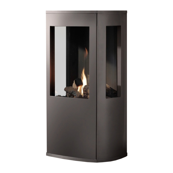
- Page 1 Trio RCE G20/G25/G25.3 (natural gas) Instructions for installation Please retain this document carefully...
-
Page 2: Table Of Contents
Figures Preface DRU, a manufacturer of gas heating appliances, develops and produces products that comply with the highest qua- lity, performance and safety requirements. This guarantees that the user will be able to enjoy using his product for many years to come. -
Page 3: Introduction
The appliance is supplied with a wireless remote control that works on batteries. CE Declaration Internal precautions at the company will guarantee that appliances produced by DRU comply with the essential requirements of the regulation concerning gas combustion appliances and the standards applied for that purpose. -
Page 4: Instructions
- Do not make any changes to the appliance. 6.2.1 Reconstruction to different type of gas If you want to convert this appliance into a different type of gas, please contact DRU’s service department and ask what is possible. Reconstructions should only be performed by authorized gas installers. -
Page 5: Placement Of The Appliance
If necessary, you can also use an existing discharge channel (see section 6.5.4). Caution - Only use the concentric system supplied by DRU (Ø100 / Ø150 mm). This system was tested in combination with the appliance; DRU cannot guarantee a proper and safe operation of other systems and cannot accept liability for these systems;... - Page 6 T R I O I N S T R U C T I O N F O R I N S TA L L AT I O N Remove the top plate from the appliance; this plate is loose; ➠ Remove the cover plate by unscrewing the 2 parkers ( ➠...
- Page 7 T R I O I N S T R U C T I O N F O R I N S TA L L AT I O N Example 1 1) 2 bends 2) 3 meters horizontal 3) 8 meters vertical/sloping →...
- Page 8 T R I O I N S T R U C T I O N F O R I N S TA L L AT I O N Examples G20 To clarify, we will give 2 examples for Gas 20, to determine the allowability of a concentric system and the conditions for setting the appliance.
-
Page 9: Connecting Gas
The following requirements apply when connecting to an existing chimney flue: - only allowed when used in combination with the special DRU chimney installation set. The installation regulation is also supplied; - the dimensions should be at least 150 x 150 mm;... -
Page 10: Placing The Wood Set
T R I O I N S T R U C T I O N F O R I N S TA L L AT I O N Place the ba e ( ➠ see Appendix 4, Fig. 4 Use the template supplied to set the distance of the restriction ( ) as follows: ➠... -
Page 11: Wireless Remote Control
T R I O I N S T R U C T I O N F O R I N S TA L L AT I O N 6.9.2 Side panes The side panes should be removed in case of torn or broken panes. 6.9.2.1 Removing the side pane Follow the steps below for removing: Carefully remove the top plate from the appliance, so that the lacquered pipe piece will not be damaged. -
Page 12: Setting The Communication Code
4, Fig. 20). For connecting an external control unit, you will need a “Domotics connection cable for GV60”. Consult DRU’s service website. The following contacts are possible: - Ignition: connect both contacts 1 + 3, for one second (if there is a 2nd thermocouple, the appliance should burn at full power for at least 20 sec. -
Page 13: Final Check
T R I O I N S T R U C T I O N F O R I N S TA L L AT I O N Final check In order to check whether the appliance is working properly and safely, you must perform the following checks before the appliance is used. -
Page 14: Flame Picture
T R I O I N S T R U C T I O N F O R I N S TA L L AT I O N 8.4 Flame picture The flame picture can only really be assessed when the appliance has been burning for several hours. Volatile com- ponents from paint, materials, etc., which evaporate in the first hours, will affect the flame picture. -
Page 15: Storingen
T R I O I N S T R U C T I O N F O R I N S TA L L AT I O N 11. Storingen Malfunction search diagram atmospheric gas- red heating appliance with electronic ignition: Starting up cycle. Start 1.05 1.01... - Page 16 T R I O I N S T R U C T I O N F O R I N S TA L L AT I O N Fires with electronic ignition, fault nding: Ignition and burning Start 2.10 Do(es) main burner(s) 2.06 Pilot can be lit.
- Page 17 Lack of combustion air. Check: two/three sided appliances ue system permissible; (no slots allowed). proper ue terminal used, make should be ‘DRU’; Flames: too high terminal correctly sited on Line pressure. roof or wall relative to Burner pressure.
-
Page 18: Appendix 1 Parts Included With The Delivery
T R I O I N S T R U C T I O N F O R I N S TA L L AT I O N Appendix 1 Parts included with the delivery In the following table you can find the parts that are supplied with the appliance. Table 5: Parts included with the delivery Part Quantity... -
Page 19: Appendix 2 Technical Data
C11, C31, C91 Category 2ELL Concentric appliance connection 150/100 DRU LAS ES-E 200/150/100 Applicable concentric systems DRU LAS ES-I 150/100, DRU LAS AG-I 150/100 Flame protection version Pilot flame with thermocouple 2nd thermocouple safety Atmosphere safety Explosion hatch Gastype Symbol G25/G25.3*... -
Page 20: Appendix 3 Parts
T R I O I N S T R U C T I O N F O R I N S TA L L AT I O N Appendix 3 Parts Parts can be ordered through www.druservice.nl... -
Page 21: Appendix 4 Figures
T R I O I N S T R U C T I O N F O R I N S TA L L AT I O N Appendix 4 Figures 38c-1218/3 Fig. 1... - Page 22 T R I O I N S T R U C T I O N F O R I N S TA L L AT I O N 1x90° 38c-744f max. 3m Fig. 2 Fig. 3 Fig. 4 Fig. 5 Fig.
- Page 23 T R I O I N S T R U C T I O N F O R I N S TA L L AT I O N Fig. 7 Fig. 8 Fig. 9 Fig. 10...
- Page 24 T R I O I N S T R U C T I O N F O R I N S TA L L AT I O N Fig. 11 Fig. 12 Fig. 13 Fig. 14...
- Page 25 T R I O I N S T R U C T I O N F O R I N S TA L L AT I O N Fig. 15 Fig. 16 Fig. 17 Fig. 18 Fig. 19...
- Page 26 T R I O I N S T R U C T I O N F O R I N S TA L L AT I O N Fig. 20 Fig. 21...
- Page 27 T R I O I N S T R U C T I O N F O R I N S TA L L AT I O N 38p-0181 38C-2031/1 Fig. 22 Fig. 23 38p-0182 38p-0179 Fig. 24 Fig. 25...
- Page 28 DRU Verwarming B.V. The Netherlands Postbus 1021, NL-6920 BA Duiven Ratio 8, NL-6921 RW Duiven...
Need help?
Do you have a question about the Trio RCE G20 and is the answer not in the manual?
Questions and answers