
Related Manuals for Dru Diablo Next RCE


Summary of Contents for Dru Diablo Next RCE
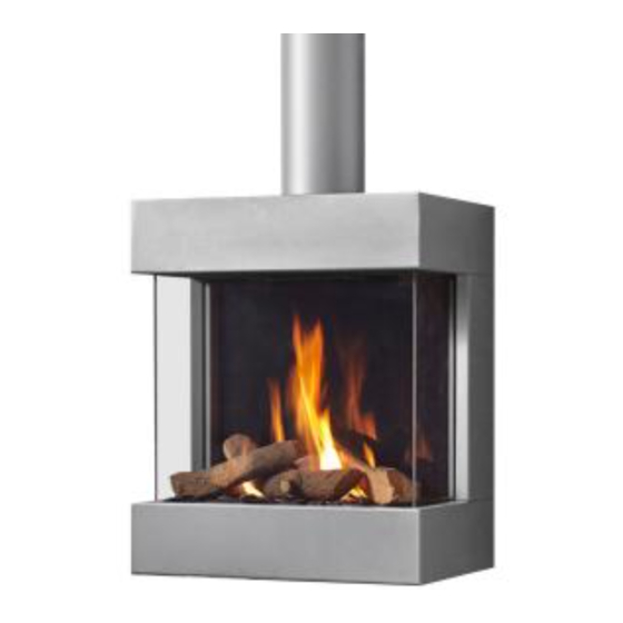
- Page 1 Diablo Next RCE Polo RCE G20/G25/G25.3 (Natural gas) G31 (Propane) 38P-0468 Installation manual Store this document in a safe place...
-
Page 2: Table Of Contents
I N S T A L LA T I O N M A N U A L Contents 1. Introduction 2. CE declaration 3. SAFETY 3.1 General 3.2 Regulations 3.3 Precautions/safety instructions during installation 3.4 Second thermocouple safety 3.5 Oxypilot safety 4. -
Page 3: Introduction
Please, read and use this installation manual carefully and completely, prior to installing this appliance. If you use the DRU Powervent system® or the DRU Smartvent system®, you must carefully and fully read and use the accompanying installation manual as well, prior to its installation. -
Page 4: Safety
CE label, and make sure there is sufficient ventilation of the room where the appliance is installed, according to legislation. Ø If you are installing an appliance with a closed combustion: only use the concentric systems supplied by DRU. Ø If you are installing a free-standing appliance: •... -
Page 5: Second Thermocouple Safety
Check whether the appliance is suitable for the type of gas and the gas pressure used at the location. !Caution 5.1.1 Reconstruction to different type of gas If you want to convert this appliance into a different type of gas, please contact DRU's service department and ask what is possible. Reconstructions should only be performed by authorized gas installers. -
Page 6: Connection
5.4 Placing a built in appliance (if applicable) Not all DRU built in appliances are supplied with a control hatch. If not included in the delivery, this control hatch is available separately. In case of appliances with closed combustion (type C11/C31) we always recommend using the Dru control hatch. -
Page 7: Placing The Chimney Breast
Placing the control hatch section 5.6; • the Dru control hatch is not supplied with all appliances. Nevertheless, we recommend only using a Dru control hatch, if available, exept in the case of B appliances. -
Page 8: Placing The Control Hatch
A number of components are placed in the control hatch, such as data plate, gas control, receiver belonging to the ® remote control and, if applicable, the components belonging to the DRU Powervent system Place the control hatch as follows; see Appendix 3, fig. 3 for details: Ø... -
Page 9: Flue Gas Discharge / Combustion Air Supply System In Appliances With Closed Combustion
(see section 5.8.4). • Only use the concentric system supplied by DRU This system has been tested in combination with the !Caution appliance. DRU cannot guarantee a proper and safe operation of other systems and does not accept any responsibility or liability for this;... - Page 10 I N S T A L LA T I O N M A N U A L The concentric system with wall or roof terminal has to comply with the following conditions: • In appendix 2, table 4 or 5 you can find whether a concentric pipe should be connected and what the minimum vertical length would have to be.
- Page 11 The surrounding space is used to supply combustion air. The following requirements apply when connecting to an existing chimney: • only allowed when used in combination with the special DRU chimney kit. The installation regulation is also supplied; •...
-
Page 12: Additional Instructions
I N S T A LL A T I O N M A N U A L 5.9 Additional instructions !Tip It will be easier to reach the gas control, if you remove the mantelpiece. 5.9.1 Placing the appliance • The temperature of the wall behind the appliance may rise up to 60°C. This should be taken into account !Caution when selecting the wall and wall covering. -
Page 13: Setting The Appliance
IN S T A LLA TION M A NU A L Make sure the front glass pane makes full contact with the side pane (there may be no opening between the side !Caution pane and front pane). If the front and side glass panes do not connect: Ø... -
Page 14: Mantelpiece
I N S T A LL A T I O N M A N U A L 5.12 Wood set The appliance is supplied with a wood set. Strictly observe the following instructions to prevent unsafe situations: !Caution • only ever use the supplied wood set; •... -
Page 15: Control
Place the receiver in its intended holder under the appliance or in the control hatch according to Appendix 3, fig. 39. • If you want to use an adapter, only an adapter supplied by DRU will guarantee a proper operation of the receiver. 6.1.1 Placing / replacing the receiver's batteries Follow the procedure below when placing the batteries: Ø... -
Page 16: Alternative Operation
(e.g. Domotics). For this purpose, there are 4 connection points at the side of the receiver (see Appendix 3, fig. 44). For connecting an external control unit, you will need a “Domotics connection cable for GV60”. Consult DRU's service website. The following contacts are possible: •... -
Page 17: Ignition Pilot And Main Burner
IN S T A LLA TION M A NU A L 7.3 Ignition pilot and main burner For igniting the pilot and main burner, see the User Manual, chapter 4, section 4.2, Remote control. 7.3.1 First ignition of the appliance after installation or adjustments !Caution After installation, or after work has been performed, you should ignite the appliance for the first time without the glass window. -
Page 18: Maintenance
I N S T A LL A T I O N M A N U A L 8. Maintenance The appliance must be inspected once per year by a skilled installer in the field of gas-fired heating, and repaired if necessary. Check at least whether the appliance is working properly and safely. -
Page 19: Delivery
IN S T A LLA TION M A NU A L 9. Delivery You must explain to the user how to operate the appliance. You must give him/her instructions on putting it in operation, the safety measures, the operation of the remote control and annual maintenance (see the User Manual). -
Page 20: Appendix 1 Diagnosis Of Malfunctions
I N S T A L LA T I ON M A N U A L Appendix 1 diagnosis of malfunctions Fires with electronic ignition, fault finding: Ignition and burning Start 2.10 Do(es) main burner(s) 2.06 Pilot can be lit. 2.08 Does main burner ignite smoothly and across 2.01 Can pilot be lit? Does it stay alight? - Page 21 Flames: too high Voltage 0 mV - proper flue terminal used, make - Line pressure. - 2nd couple defective. should be 'DRU'; - Burner pressure. - Cross ligting main burner very slow. - terminal correctly sited on roof or Take actions "Cross lighting too wall relative to obstructions;...
- Page 22 I N S T A LL A T I O N M A N U A L Malfunction search diagram atmospheric gas-fired heating appliance with electronic ignition: Starting up cycle. Start 1.05 1.01 Does receiver beep? 1.03 Short sound signals, 1 sec after One long 5 second beep, (possibly each other, followed by the preceded by 7 short beeps).
-
Page 23: Appendix 2 Various Tables
IN S T A LLA TION M A NU A L Appendix 2 Tables Table 1: Parts included with the delivery Part Number Wood set Glow material Installation manual User manual Key bolts M6 x 60 x 40 mm Washer M6 Spare self-tapping screws for mounting the glass panes Socket spanner 8 mm Remote control with receiver 9V block battery... - Page 24 C11, C31, C91 Categorie 2ELL Concentric appliance connection 150/100 Applicable concentric systems DRU LAS ES-E 200/150/100, DRU LAS ES-I 150/100, DRU LAS AG-I 150/100 Flame protection version Pilot flame with thermocouple 2nd thermocouple safety Atmosphere safety Explosion hatch Ventilation hole chimney breast...
- Page 25 IN S T A LLA TION M A NU A L Table 3: Line-pressure when using G31 Country mbar NL / DK / FI / NO / SE / HU / BA / GR FR / BE / IT / PT / ES / GB / IE Permissibility and conditions concentric system with wall terminal ...
- Page 26 I N S T A L LA T I ON M A N U A L Table 5: Determining permissibility concentric systemwith roof terminal G20/G25/G25.3/ Total number of meters Total no. of meters vertical and/or sloping pipe length horiz. pipe length no bends 2 bends 3 bends...
-
Page 27: Appendix 3 Figures
IN S T A LLA TION M A NU A L Appendix 3 Figures 38C-1994/0 196,1 38C-1992/1 Diablo Next 568 min. 1x90° 38C-744zk 38C-1995/1 0 - 5m G20/G25/G25.3 G 3/8" G 3/8" 38C-2008/0 38C-2007/0... - Page 28 I N S T A LL A T I O N M A N U A L 38C-1997/0 38C-1996/1 38C-1998/0 38C-1999/0 38C-2000/1...
- Page 29 IN S T A LLA TION M A NU A L 38C-2003/0 38C-2002/0 38C-2005/1 38C-2004/1...
- Page 30 I N S T A LL A T I O N M A N U A L 38P-0467 38P-0466 38p-0022 38p-0023 38P-0028 /1 38P-0461...
- Page 31 IN S T A LLA TION M A NU A L 38P-0381 38P-0462...
- Page 32 I N S T A LL A T I O N M A N U A L 38P-0463 38P-0464...
- Page 33 IN S T A LLA TION M A NU A L 38P-0465 38P-0469...
- Page 34 I N S T A LL A T I O N M A N U A L 38p-0181 38p-0179 38C-2006/0 38p-0182...
- Page 35 IN S T A LLA TION M A NU A L 38C-1940...
- Page 36 DRU Verwarming B.V. The Netherlands Postbus 1021, NL-6920 BA Duiven Ratio 8, NL-6921 RW Duiven EN ...
Need help?
Do you have a question about the Diablo Next RCE and is the answer not in the manual?
Questions and answers