Fronius VR 4000 Operating Instructions/Spare Parts List
Wire-feed unit
Hide thumbs
Also See for VR 4000:
- Operating instructions manual (60 pages) ,
- Installation instructions manual (33 pages)
Table of Contents
Advertisement
Advertisement
Table of Contents

Related Manuals for Fronius VR 4000


Summary of Contents for Fronius VR 4000
- Page 1 / Perfect Charging / Perfect Welding / Solar Energy Operating Instructions VR 4000 Spare parts list VR 4000-30 Wire-feed unit VR 4000-30 TIME 42,0426,0012,EN 003-16082017 Fronius prints on elemental chlorine free paper (ECF) sourced from certified sustainable forests (FSC).
- Page 3 Thank you for the trust you have placed in our company and congratulations on buying this high-quality Fronius product. These instructions will help you familiarise yourself with the product. Reading the instructions carefully will enable you to learn about the many different features it has to offer.
-
Page 5: Table Of Contents
Device concept ............................. REQUIREMENTS ..........................Application area ............................ Warning notices on the device......................Options............................... "Mode" switch option for VR 4000/VR 4000-30 ..................Optional control panels for VR 4000/VR 4000-30................. Optional installation and conversion kits....................Controls and indicators ..........................General .............................. - Page 6 Requirements............................Care, maintenance and disposal ....................... General remarks ........................... Every start-up............................Every 6 months ............................. Disposal ..............................Technical data............................VR 4000 ..............................VR 4000-30............................VR 4000-30 TIME ..........................Appendix Spare parts list: VR 4000 TIME, VR 4000, VR 4000-30 ................
-
Page 7: Safety Rules
Safety rules General The device is manufactured using state-of-the-art technology and according to recognised safety standards. If used incorrectly or misused, however, it can cause: injury or death to the operator or a third party, damage to the device and other material assets belonging to the operat- ing company, inefficient operation of the device. -
Page 8: Environmental Conditions
Environmental Operation or storage of the device outside the stipulated area will be deemed conditions as not in accordance with the intended purpose. The manufacturer shall not be held liable for any damage arising from such usage. Ambient temperature range: during operation: -10 °C to + 40 °C (14 °F to 104 °F) during transport and storage: -20 °C to +55 °C (-4 °F to 131 °F) Relative humidity:... -
Page 9: Protecting Yourself And Others
Protecting your- Persons involved with welding expose themselves to numerous risks, e.g.: self and others flying sparks and hot pieces of metal arc radiation, which can damage eyes and skin hazardous electromagnetic fields, which can endanger the lives of those using cardiac pacemakers risk of electrocution from mains current and welding current greater noise pollution... -
Page 10: Danger From Flying Sparks
Otherwise, a protective mask with an air supply must be worn. Close the shielding gas cylinder valve or main gas supply if no welding is tak- ing place. If there is any doubt about whether the extraction capacity is sufficient, the measured toxic emission values should be compared with the permissible limit values. -
Page 11: Meandering Welding Currents
All cables and leads must be secured, undamaged, insulated and adequately dimensioned. Replace loose connections and scorched, damaged or inade- quately dimensioned cables and leads immediately. Use the handle to ensure the power connections are tight before every use. In the case of power cables with a bayonet connector, rotate the power cable around the longitudinal axis by at least 180°... -
Page 12: Emc Device Classifications
EMC Device Clas- Devices in emission class A: sifications Are only designed for use in industrial settings Can cause line-bound and radiated interference in other areas Devices in emission class B: Satisfy the emissions criteria for residential and industrial areas. This is also true for residential areas in which the energy is sup- plied from the public low-voltage mains. -
Page 13: Specific Hazards
Specific hazards Keep hands, hair, clothing and tools away from moving parts. For example: Fans Cogs Rollers Shafts Wirespools and welding wires Do not reach into the rotating cogs of the wire drive or into rotating drive com- ponents. Covers and side panels may only be opened/removed while maintenance or repair work is being carried out. -
Page 14: Factors Affecting Welding Results
If the device has a carrying strap or handle, this is intended solely for carrying by hand. The carrying strap is not to be used if transporting with a crane, coun- terbalanced lift truck or other mechanical hoist. All lifting accessories (straps, handles, chains, etc.) used in connection with the device or its components must be tested regularly (e.g. -
Page 15: Safety Measures At The Installation Location And During Transport
Safety measures A device toppling over could easily kill someone. Place the device on a solid, at the installation level surface such that it remains stable location and dur- The maximum permissible tilt angle is 10°. ing transport Special regulations apply in rooms at risk of fire or explosion Observe relevant national and international regulations. -
Page 16: Commissioning, Maintenance And Repair
Used coolant must be disposed of properly in accordance with the relevant na- tional and international regulations. The coolant safety data sheet may be ob- tained from your service centre or downloaded from the manufacturer's website. Check the coolant level before starting to weld and while the system is still cool. -
Page 17: Safety Symbols
(e.g. relevant product standards of the EN 60 974 series). Fronius International GmbH hereby declares that the device is compliant with Directive 2014/53/EU. The full text on the EU Declaration of Conformity can be found at the following address: http://www.fronius.com Devices marked with the CSA test mark satisfy the requirements of the rele- vant standards for Canada and the USA. -
Page 18: General
Due to their compact size, the wirefeeders can be used in many different ways. The VR 4000-30 TIME wire-feed unit is specially designed for the TIME high-performance welding process. All the important TIME process functions can be set directly on the wire- feed unit control panel using the integrated 3-parameter control. -
Page 19: Warning Notices On The Device
All variants of the VR 4000 are suitable for all standard shielding gases. NOTE! The VR 4000 - 30 and VR 4000-30 TIME wire-feed units have a water- cooled electric motor with disc-shaped rotor, and may only be operated in con- junction with an appropriate cooling unit. -
Page 20: Options
NOTE! The "Mode selector switch" option cannot be used in conjunction with the VR 4000 digital display control panel. Optional control The VR 4000 and VR 4000-30 wire-feed units can, as an alternative to the standard control panels for VR panel, be fitted with the following control panels:... - Page 21 Plastic-to-metal adapter installation kit for subsequent changeover from plastic to metal connection sockets Gas test/wire threading installation kit for retrofitting of a rocker switch for gas test and wire threading Trabant for installing the wire-feed unit on the Trabant trolley Fixable tensioning lever installation kit for retrofitting a fixable tensioning lever so that contact pressure cannot be accidentally adjusted...
-
Page 22: Controls And Indicators
Controls and indicators General WARNING! Operating the equipment incorrectly can cause serious injury and damage. Do not use the functions described here until you have fully read and understood the following documents: These operating instructions all the operating instructions for the system components, especially the safe- ty rules Setting parameters at control panels is only possible in manual welding mode. -
Page 23: Control Panel Vr 4000-30 Time
Control panel VR The VR 4000-30 TIME wire-feed unit is part of the TIME high-performance welding system. 4000-30 TIME The 3-parameter control allows you to set the starting, main and final currents individually, which is necessary for high-performance welding. (10) - Page 24 (4) is set to operating point 3 operating point 3 is running IMPORTANT! If using the VR 4000-30 TIME wire-feed unit, the "Job mode" function is not available. After connecting the wirefeeder, the only welding processes that can be selected...
-
Page 25: Connections And Mechanical Components
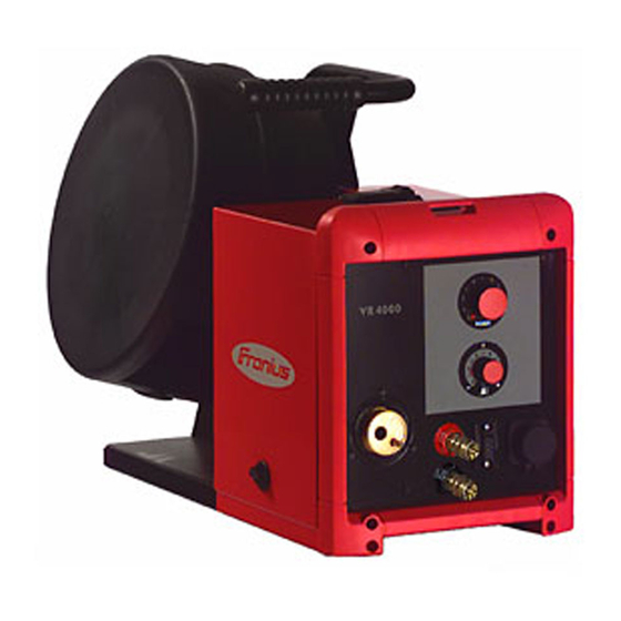
Connections and mechanical components Front of wirefeed- VR 4000 - front view VR 4000-30 TIME - front view Welding torch connection to hold the welding torch Water return connection (red) Water flow connection (blue) Torch control connection for connecting the torch control plug LocalNet connection standardised connection socket for system add-ons (e.g. -
Page 26: Side Of Wire-Feed Unit
Side of wire-feed unit VR 4000 - side view Wirespool holder with brake for attaching standardised wirespools up to max.16 kg (35.27 lbs.) and with a max- imum diameter of 300 mm (11.81 in.) 4-roller drive "Wire threading/gas test" button To feed the wire electrode into the torch hosepack with no accompanying flow of gas or current. - Page 27 IMPORTANT! If settings have been selected using the "Mode selector switch" option, they cannot be changed using other controls, for example: the control panel on the front of the power source on the front of the wire-feed unit on the remote control...
-
Page 28: Placing Wire-Feed Unit On Power Source
Placing wire-feed unit on power source General The wire-feed units can be placed on the power source if a swivel pin holder is available, e.g.: "PickUp" swivel pin receptor, for use with the "PickUp" trolley "narrow" swivel pin receptor, for use with an upright console "wide"... -
Page 29: Connecting Wire-Feed Unit To Power Source
Connecting wire-feed unit to power source General The wirefeeder is connected to the power source using the interconnecting hosepack. Connecting the WARNING! An electric shock can be fatal. If the machine is plugged in during in- wirefeeder to the stallation, there is a high risk of very serious injury and damage. Only carry out power source work on the device when the power source mains switch is in the "O"... -
Page 30: Connecting The Welding Torch
Euro connection for Dinse for Tweco connections VR 4000 VR 4000-30 VR 4000-30 TIME Safety NOTE! When connecting the welding torch, check that all connections are connected properly all cables, leads and hosepacks are undamaged and correctly insulated. Connecting MIG/... -
Page 31: Connecting The Tweco Welding Torch
Connecting the Switch the power source mains switch Tweco welding to the "0" position torch Open the wirespool cover Insert the welding torch, infeed tube first, into the welding torch connection Inserting the welding torch into the connection for Twe- Fix the welding torch in place using a knurled screw (6) Fixing welding torch in place using a knurled screw... -
Page 32: Inserting/Replacing Feed Rollers
Inserting/replacing feed rollers General remarks In order to achieve optimum wire electrode feed, the feed rollers must be suitable for the diameter and alloy of the wire being welded. IMPORTANT! Only use feed rollers that match the wire electrode. An overview of the feed rollers available and their possible areas of use can be found in the spare parts lists. -
Page 33: Inserting The Wirespool, Inserting The Basket-Type Spool
Inserting the wirespool, inserting the basket-type spool Safety CAUTION! Risk of injury from springiness of spooled wire electrode. When insert- ing the wirespool/basket-type spool, hold the end of the wire electrode firmly to avoid injuries caused by the wire electrode springing back. CAUTION! Risk of injury from falling wirespool/basket-type spool. -
Page 34: Feeding In The Wire Electrode
Feeding in the wire electrode Feed in the wire CAUTION! Risk of injury from springiness of spooled wire electrode. When insert- electrode ing the wire electrode into the 4 roller drive, hold the end of the wire electrode firm- ly to avoid injuries caused by the wire springing back. CAUTION! Risk of damage to the welding torch from sharp end of wire electrode. -
Page 35: Set The Contact Pressure
Set the contact pressure NOTE! Set the contact pressure in such a way that the wire electrode is not deformed but nevertheless ensures proper wirefeeding. Contact pressure stand- Semi-cylindrical Trapeze rolls Plastic rollers ard values rolls Aluminium 3.5 - 4.5 Steel 3 - 4 CrNi... -
Page 36: Adjust The Brake
Adjust the brake Adjusting the NOTE! After releasing the torch trigger the wirespool should stop unreeling. Ad- brake just brake if necessary. STOP STOP Design of the WARNING! Fitting the equipment brake incorrectly can cause serious inju- ry and damage. Do not dismantle the brake. -
Page 37: Start-Up
Start-up General informa- WARNING! Operating the equipment incorrectly can cause serious injury and tion damage. Do not use the functions described until you have thoroughly read and understood the following documents: these operating instructions all the operating instructions for the system components, especially the safe- ty rules The wire-feed unit is commissioned by pressing the torch trigger (for manual applications) or by means of a welding start-up signal (for automatic applications). -
Page 38: Care, Maintenance And Disposal
Care, maintenance and disposal General remarks Under normal operating conditions, the wire-feed unit requires only a minimum of care and maintenance. However, some important points must be noted to ensure that the welding system remains in a usable condition for many years. WARNING! An electric shock can be fatal. -
Page 39: Technical Data
Technical data VR 4000 Supply voltage 55 V DC (supply from the power source) Nominal current Wire speed 0.5 - 22 m/min 19.69 - 866.14 ipm Degree of protection IP 23 Dimensions l x w x h 650 x 290 x 410 mm 25.59 x 11.42 x 16.14 in. -
Page 40: Vr 4000-30 Time
Original Fronius Maximum coolant pressure 6 bar 87 psi LocalNet data rate 57600 Baud VR 4000-30 TIME Supply voltage 55 V DC (supply from the power source) Nominal current Wire speed 0.5 - 30 m/min 19.69 - 1181.10 ipm... -
Page 41: Appendix
Appendix... -
Page 42: Spare Parts List: Vr 4000 Time, Vr 4000, Vr 4000-30
Spare parts list: VR 4000 TIME, VR 4000, VR 4000-30... - Page 43 Motorplate 42V 4R 42,0400,0123 42,0405,0116 42,0407,0098 42,0404,0264 BF2,0404,0340 - yellow 42,0409,2106 32,0405,0112 32,0405,0113 42,0405,0117 - PE 42,0200,9352 - CuZn 42,0200,7767 t o r t o r 42,0405,0120 42,0300,2162 44,0001,1203 42,0407,0077 42,0407,0503 42,0406,0034 42,0100,0333 - PE 42,0001,3481 - Fe 22,0405,0114 42,0405,0119 BF2,0201,1345...
- Page 48 Connection hose pack W 1,2m 70mm² 4,047,260 W 1,6m 70mm² 4,047,324 W 5,0m 70mm² 4,047,261 W 10m 70mm² 4,047,262 W 15m 70mm² 4,047,290 W 20m 70mm² 4,047,277 G 1,2m 70mm² 4,047,287 32,0405,0226 G 5,0m 70mm² 4,047,288 42,0407,0482 G 10m 70mm² 4,047,289 40,0001,0095 - * 42,0405,0239...
- Page 49 Connection hose pack G 50mm² 4m 4,047,411 G 70mm² 8m 4,047,412 32,0405,0226 42,0407,0482 40,0001,0095 - * 42,0405,0239 42,0407,0482 32,0405,0226 44,0450,0281 - G 1/4" 42,0407,0063 43,0003,0251 40,0001,0012 - * 43,0003,0253 42,0405,0239 42,0407,0048 40,0003,0447 - * 42,0407,0063 44,0450,0281 - G 1/4" 43,0003,0063 - 50mm² 43,0003,0064 - 70mm²...
- Page 50 Connection hose pack G 50mm² 1,2m 4,047,408 G 50mm² 5m 4,047,409 G 50mm² 10m 4,047,410 32,0405,0226 42,0407,0482 40,0001,0095 - * 42,0405,0239 42,0407,0482 44,0450,0281 - G 1/4" 32,0405,0226 42,0407,0063 43,0003,0485 40,0001,0012 - * 32,0405,0232 42,0405,0239 32,0405,0180 42,0407,0048 40,0003,0078 - * 42,0407,0063 44,0450,0281 - G 1/4"...
- Page 51 Connection hose pack W 4m 95mm² 4,047,291 W 8m 95mm² 4,047,292 W 8m 95mm² 4,047,292,800 ** W 10m 95mm² 4,047,396 32,0405,0226 42,0407,0482 40,0001,0095 - * 42,0405,0239 42,0407,0482 42,0407,0063 32,0405,0226 42,0402,0053 40,0001,0012 - * 42,0001,0942 42,0001,0943 42,0405,0239 44,0450,0281 - G 1/4" 43,0003,0251 43,0003,0253 42,0407,0048...
- Page 52 FRONIUS INTERNATIONAL GMBH Froniusplatz 1, A-4600 Wels, Austria Tel: +43 (0)7242 241-0, Fax: +43 (0)7242 241-3940 E-Mail: sales@fronius.com www.fronius.com www.fronius.com/addresses Under http://www.fronius.com/addresses you will find all addresses of our Sales & service partners and Locations...
Need help?
Do you have a question about the VR 4000 and is the answer not in the manual?
Questions and answers