Table of Contents
Advertisement
Quick Links
Instruction
Manual
Thank you for purchasing our product.
This manual provides important information about safe and proper operations
of this Switching Hub.
Please read 「Important Safety Instructions」 on pages 3 to 5 before use.
For target model names and numbers, refer to the next page.
Under all circumstances, customer disassembling of this Switching Hub voids the
warranty.
Layer 2 Switching Hub
Model No. PN25041/PN25048
PN25101/PN25108
PN25121/PN25128
Advertisement
Table of Contents

Related Manuals for Panasonic GA-AS12TPoE+ Series


Summary of Contents for Panasonic GA-AS12TPoE+ Series
- Page 1 Layer 2 Switching Hub Instruction Model No. PN25041/PN25048 Manual PN25101/PN25108 PN25121/PN25128 Thank you for purchasing our product. This manual provides important information about safe and proper operations of this Switching Hub. Please read 「Important Safety Instructions」 on pages 3 to 5 before use. ...
- Page 2 The target model for this Instruction Manual is as follows. Model name Model number Firmware version PN25048-ID PN25048-TH GA-AS4TPoE+ 1.0.0.14 and above PN25048-MY PN25048-SG PN25108-ID PN25108-TH GA-AS10TPoE+ 1.0.0.14 and above PN25108-MY PN25108-SG PN25128-ID PN25128-TH GA-AS12TPoE+ 1.0.0.14 and above PN25128-MY PN25128-SG PN25041-ID PN25041-TH GA-AS4T...
-
Page 3: Important Safety Instructions
Important Safety Instructions Please Follow the Instructions This chapter contains important safety instructions for preventing bodily injury and/or property damage. You are required to follow them. ■Severity of bodily injury and/or property damage, which could result from incor- rect use of this Switching Hub, is explained below. This symbol indicates a potential hazard that could result in serious injury or death. - Page 4 ● Do not store and/or use this Switching Hub at a location where liq- uid (water) may be spilled, or high humidity, conductive dust, corro- sive gas, flammable gas is present. Deviation could lead to fire, electric shock, and/or equipment failure. ●...
- Page 5 ● Perform maintenance at periodic intervals to maintain perfor- mance. Assign an administrator for this product and make sure to perform periodic maintenance. Refer to Panasonic Eco Solutions Network's web site for the inspection table that lists all required items to be checked during maintenance.
- Page 6 ● When using this Switching Hub for a purpose that requires extremely high reliability, take all possible measures to ensure safety and reliability. This Switching Hub is not designed and/or manufactured with the intent of being used for applications that require extremely high reli- ability (application in the railways, aviation, medical areas in which adverse effects caused by communication failure or those that directly affect human life must be avoided).
-
Page 7: Basic Instructions For The Use Of This Product
Basic Instructions for the Use of This Product ● For internal inspection and/or repair, please contact your dealer. ● Use commercial power supply from a wall socket, which is close and easily accessible from this Switching Hub. ● Unplug the power cord when installing or moving this Switching Hub. ●... - Page 8 ● When mounting the Switching Hub in a rack, ensure clearance of 20 mm or more between upper or lower device. 1. Panasonic will not be liable for any damage (including but not limited to loss of profits, loss of opportunity, etc.) resulting from the operation not in accordance with this operation manual, which may or may not be caused by failure and/or malfunction of this device.
-
Page 9: Table Of Contents
Table of Contents Important Safety Instructions ................3 ● Basic Instructions for the Use of This Product ..........7 Product Outline ..................11 1.1. Features ....................11 1.2. Accessories ..................12 1.3. Optional Parts ..................13 1.4. Part Names and Functions ..............14 1.5. - Page 10 5.2.4.Traffic Class Config ................47 5.2.5.Diffserv Config ................48 5.2.6.Link Aggregation Config ..............49 5.2.6.a. Link Aggregation Modification ..........50 5.2.7.Storm Control Config ..............51 5.2.8.Port Monitoring Config ..............52 5.2.9.Static Multicast Address Config ............54 5.2.10.PoE Port Config (for PoE Supported Models) ......... 55 5.2.11.PoE Global Config (for PoE Supported Models) ......
-
Page 11: Product Outline
1. Product Outline GA-AS4TPoE+/GA-AS10TPoE+/GA-AS12TPoE+/GA-AS4T/GA-AS10T/GA-AS12T are Ethernet Switching Hubs that feature the Web control function and 10/100/ 1000BASE-T ports. The downlink ports support the PoE power supply function for IEEE802.3at/af compatible devices. 1.1. Features ・ All ports (twisted pair ports) are 10/100/1000BASE-T ports that support auto- negotiation. -
Page 12: Accessories
1.2. Accessories Please be sure to confirm the contents. Please contact your dealer if any item is missing. ・ Switch ・ Operation Manual ・ CD-ROM (including Operation Manual (this manual), ZEQUO assist Plus) ・ Rubber foot ・ Power cord... -
Page 13: Optional Parts
1.3. Optional Parts ・ PN71051 19-inch rack mount bracket (for one unit) ・ PN71052 19-inch rack mount bracket (for connecting two units) ・ PN71053 Wall-mount bracket... -
Page 14: Part Names And Functions
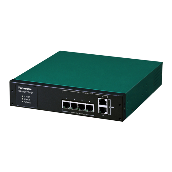
1.4. Part Names and Functions Power port MAC address label Power cord hook block Back Ground terminal screw Manufacture number label Front 10BASE-T/100BASE-TX/1000BASE-T See next page for enlarged figure Figure 1-1 External View (Example: GA-AS4TPoE+) ● Power port Connect the supplied power cord into the port and connect the other end into an electric outlet (AC 100-240 V). -
Page 15: Led Behavior
1.5. LED Behavior 1.5.1. LED Behavior during Start-up When you turn on this switch, all LEDs are lit momentarily. Then, self-diagnosis of the hardware is conducted. When the self-diagnosis is com- pleted, the STATUS LED is lit in green, and the hardware starts operation as a switching hub. -
Page 16: Led Behavior While Operating
1.5.2. LED Behavior while Operating Each switch has system LEDs and a set of LEDs for each port. These LEDs indicate the operation status of the switch and each port. ・ System LEDs POWER LED (Power) STATUS LED (Status) PoE LIM. LED (PoE limit) Figure 1-2 System LEDs (Example: GA-AS4TPoE+) Behavior Description... - Page 17 ・ Port LEDs Port LED (Left) Port LED (Right) Figure 1-3 Port LEDs (Example: GA-AS10TPoE+) Port LEDs Behavior Description Left LINK/ACT Green Link established. light Green Transmitting data. blink No device connected. Right Green Supplying power normally. (PoE sup- light port device Green The whole unit or the single port is overloaded.
-
Page 18: Operation Overview Of Poe Power Supply Function On Poe Supported Models
1.5.3. Operation Overview of PoE Power Supply Func- tion on PoE Supported Models The downlink ports of GA-AS4TPoE+/AS10TPoE+/AS12TPoE+ can provide PoE power supply for IEEE802.3at/af compatible devices. A single port can supply power up to 30 W. The number of downlink ports and amount of power supply by the whole unit are shown below for each model. -
Page 19: Installation
2. Installation For the installation methods for each model, refer to the operating instructions (paper) provided with each switch. -
Page 20: Connection
3. Connection 3.1. Connecting a Twisted Pair Port ・ Connection Cable Use a CAT5E or higher straight cable (twisted pair cable) with 8P8C RJ45 modu- lar plugs. ・ Network Configuration Within 100 m Within 100 m Within 100 m Figure 3-1 Connection configuration example The length of the cable connecting this switch and a device must be 100 m or shorter. -
Page 21: Connecting To Power
3.2. Connecting to Power Connect the supplied power cord to the power port of this switch, and connect the power plug into an electric outlet. The switch operates at AC 100-240 V (50/60 Hz). It does not have a power switch. When you connect the power plug, the switch turns on and starts operating. -
Page 22: Web Browser-Based Control
4. Web Browser-based Control With the web browser-based control function (hereinafter referred to as the "Web control function"), you can configure the settings for this switch from a web browser's user interface via the network. 4.1. Operating Environment The terminal to be accessed should have Microsoft Internet Explorer 11 installed. Also, the terminal needs to directly connect to a network or this switch. -
Page 23: Ip Address Configuration
4.2. IP Address Configuration The IP address of this switch is not set as factory default. To access the Web con- trol function screen for this switch, you need to use the ZEQUO assist Plus applica- tion included in the CD-ROM provided with the switch to set the IP address. For details, refer to the operating instructions (paper) provided with each switch or the operation instructions for ZEQUO assist Plus. -
Page 24: Access To Web Control Function
4.3. Access to Web Control Function To use the Web control function, enter the IP address for this switch in the web browser's URL field ("location:", "address:", etc.) and press "Enter." Then, a login screen for this switch shown in Figure 4-1 is displayed. Enter the user name and password. - Page 25 When the above information has been authenticated properly, the screen shown in Figure 4-2 will appear for selecting a display language. Select the type of the language in which you want to show menus, and press "OK." Figure 4-2 Select Display Language...
- Page 26 The left side of the screen shows a list of actions that you can perform on this screen. (1) General Info Displays a list of basic information of this switch. (2) Basic Config Configure the basic settings such as IP address and port settings. (3) Advanced Config Configure the advanced function settings such as VLAN, QoS, and port moni- toring.
-
Page 27: Displaying Basic Information
4.4. Displaying Basic Information Select "General Info" to open the screen shown in Figure 4-3. This screen displays a list of this switch's basic information. Figure 4-3 General Info... - Page 28 Screen Description System Informa- Displays the operating time and firmware version of this switch. tion Operating Time Displays the cumulative time since the power on of this switch. Boot Code Ver- Displays the firmware version of this switch. * The firmware sion update described in Section 5.3.1 is available only for run- time codes.
-
Page 29: Switch Configuration
5. Switch Configuration After completing configuration, you must save the configuration information in accordance with Section 5.3.3. Unless you save the configuration information, the settings configured so far will not be reflected upon restart. 5.1. Basic Config 5.1.1. Administration Config Select "Basic Config"... -
Page 30: Ip Config
5.1.2. IP Config Select "Basic Config" and then "IP Config" to open the screen shown in Figure 5-2. On this screen, you can configure the IP address of this switch. Figure 5-2 IP Config Screen Description MAC Address Displays the MAC address of this switch. This value is uniquely assigned to each device and cannot be changed. -
Page 31: Basic Port Config
5.1.3. Basic Port Config Select "Basic Config" and "Port Config" and then "Basic Port Config" to open the screen shown in Figure 5-3. On this screen, you can display status and configure mode and other settings for each port. Figure 5-3 Basic Port Configuration... - Page 32 Screen Description Port Number Displays the port number. Type Displays the port type. 1000T The port type is 1000BASE-T. Link Status Displays the current link status. A link has been established successfully. Down A link has not been established. Port Status Displays the current port status.
-
Page 33: Extend Port Config
5.1.4. Extend Port Config Select "Basic Config" and "Port Config" and then "Extend Port Config" to open the screen shown in Figure 5-4. On this screen, you can display status and configure mode and other settings for each port. Figure 5-4 Extend Port Config Screen Description Global Jumbo Status Displays the jumbo frame settings. -
Page 34: Power Saving Config
5.1.5. Power Saving Config Select "Basic Config" and "Port Config" and then "Power Saving Config" to open the screen shown in Figure 5-5. On this screen, you can configure the power saving settings of each port. Figure 5-5 Power Saving Port Config Screen Description Port Number Displays the port number. -
Page 35: System Security
IP Setup Interface Displays the access settings for the IP address configuration software, bundled Status with the ZEQUO assist Plus and Panasonic network cameras. "Enable" is the fac- tory default setting.* For instructions, refer to "6.2.Easy IP Address Setup Func- tion". -
Page 36: Syslog Transmission Config
5.1.7. Syslog Transmission Config Select "Basic Config" and "System Security" and then "Syslog Transmission Config" to open the screen shown in Figure 5-7. On this screen, you can configure the set- tings of the Syslog server information to which a system log is sent. Figure 5-7 Syslog Transmission Configuration Screen Description Global Syslog... -
Page 37: Id/Password Change
5.1.8. ID/Password Change Select "Basic Config" and "System Security" and then "ID/Password Change" to open the screen shown in Figure 5-8. On this screen, you can configure the user name/password. Figure 5-8 ID/Password Change Screen Description Current User ID Enter the current user name. This is used to login to this switch. -
Page 38: Fdb Table
5.1.9. FDB Table Select "Basic Config" and "FDB" and then "FDB Table" to open the screen shown in Figure 5-9. This screen shows the MAC addresses learned in the FDB table for each port. Figure 5-9 FDB Table Screen Description Aging Time Displays the time for which an automatically learned FDB entry is retained. -
Page 39: Time Config
5.1.10. Time Config Select "Basic Config" and then "Time Config" to open the screen shown in Figure 5- 10. On this screen, you can configure the SNTP synchronization settings. Figure 5-10 Time Configuration of This Switch Screen Description Time Zone Displays the time zone. -
Page 40: Static Arp Table
5.1.11. Static ARP Table Select "Basic Config" and "ARP Table" and then "Static ARP Table" to open the screen shown in Figure 5-11. On this screen, you can statically associate the IP address and MAC address and register that relationship to the ARP table. Figure 5-11 Static ARP Table Screen Description IP Address... -
Page 41: Arp Table
5.1.12. ARP Table Select "Basic Config" and "ARP Table" and then "ARP Table" to open the screen shown in Figure 5-12. This screen shows the ARP table. Figure 5-12 ARP Table Screen Description ARP Age Timeout Displays the time for which an automatically learned ARP table is retained. It is equal to the time after receiving the last packet. -
Page 42: Advanced Switch Configuration
5.2. Advanced Switch Configuration 5.2.1. VLAN Management Select "Advanced Config" and "VLAN" and then "VLAN Management" to open the screen shown in Figure 5-13. On this screen, you can configure the VLAN-related settings. Figure 5-13 VLAN Management Screen Description VLAN Status Displays the VLAN status. - Page 43 Management Indicates whether the VLAN is a management VLAN or not. VLAN Indicates that the VLAN is a management VLAN (VLAN that can communicate with the CPU). Down Indicates that the VLAN is not a management VLAN.
-
Page 44: Vlan Modification
5.2.1.a. VLAN Modification On the "VLAN Management" screen, select "Modify" to open the screen shown in Figure 5-14. On this screen, you can modify the VLAN configuration information. Figure 5-14 "VLAN Modification" Screen Screen Description VLAN ID Displays the VLAN ID. VLAN Name Displays the VLAN name. -
Page 45: Vlan Creation
5.2.2. VLAN Creation Select "Advanced Config" and "VLAN" and then "VLAN Creation" to open the screen shown in Figure 5-15. On this screen, you can create a new VLAN. Figure 5-15 "VLAN Creation" Screen Screen Description VLAN ID Set the VLAN ID. VLAN Name Set the VLAN name. -
Page 46: Vlan Port Config
5.2.3. VLAN Port Config Select "Advanced Config" and "VLAN" and then "VLAN Port Config" to open the screen shown in Figure 5-16. On this screen, you can configure the VLAN port set- tings. Figure 5-16 VLAN Port Config Screen Description Port Number Displays the port number. -
Page 47: Traffic Class Config
5.2.4. Traffic Class Config Select "Advanced Config" and "QoS Config" and then "Traffic Class Config" to open the screen shown in Figure 5-17. On this screen, you can configure the QoS and Traffic Class settings. Figure 5-17 QoS Config Screen Description Displays "Enable"/"Disable"... -
Page 48: Diffserv Config
5.2.5. Diffserv Config Select "Advanced Config" and "QoS Config" and then "Diffserv Config" to open the screen shown in Figure 5-18. On this screen, you can configure the Diffserv set- tings. Figure 5-18 Diffserv Settings Screen Description Diffserv Status Displays "Enable"/"Disable" of the Diffserv function. "Disable" is the factory default setting. -
Page 49: Link Aggregation Config
5.2.6. Link Aggregation Config Select "Advanced Config" and then "Link Aggregation Config" to open the screen shown in Figure 5-19. On this screen, you can configure the group settings of link aggregation. Figure 5-19 Link Aggregation Config Screen Description Displays the group number of the link aggregation. Member Port List Displays the ports that belong to the group of link aggregation. -
Page 50: Link Aggregation Modification
5.2.6.a. Link Aggregation Modification Select "Advanced Config" and "Link Aggregation Config" and then click the "Mod- ify" button of each group to open the screen shown in Figure 5-20. On this screen, you can modify the link aggregation. Figure 5-20 Link Aggregation Modification Screen Description Displays the group number of the link aggregation. -
Page 51: Storm Control Config
5.2.7. Storm Control Config Select "Advanced Config" and then "Storm Control Config" to open the screen shown in Figure 5-21. On this screen, you can configure the storm control settings. Figure 5-21 Storm Control Configuration Screen Description Port Number Displays the port number. Unknown Unicast Enables or disables the Unknown unicast storm control. -
Page 52: Port Monitoring Config
5.2.8. Port Monitoring Config Select "Advanced Config" and then "Port Monitoring Config" to open the screen shown in Figure 5-22. On this screen, you can configure the port monitoring set- tings. Figure 5-22 Port Monitoring Configuration Screen Description Monitor Output Port Indicates a port number of a port used to monitor packets for another port. - Page 53 Note: Administrative packets such as Ping and ARP transmitted by this switch can- not be captured.
-
Page 54: Static Multicast Address Config
5.2.9. Static Multicast Address Config Select "Advanced Config" and then "Static Multicast Address Config" to open the screen shown in Figure 5-23. On this screen, you can manually register multicast addresses. Figure 5-23 Multicast Address Manual Register Screen Description VLAN ID Displays the VLAN ID of the multicast group. -
Page 55: Poe Port Config (For Poe Supported Models)
5.2.10. PoE Port Config (for PoE Supported Models) Select "Advanced Config" and "PoE Config" and then "PoE Port Config" to open the screen shown in Figure 5-24. On this screen, you can configure the power supply settings by port. Figure 5-24 PoE Port Config... - Page 56 Screen Description Port Number Displays the port number. Admin. Displays whether or not the power can be supplied. Power supply is possible. Down Power supply is not possible. Status Displays the power supply status. Powered Indicates that power is supplied by PoE. Not Powered Indicates that power is not supplied by PoE.
-
Page 57: Poe Global Config (For Poe Supported Models)
5.2.11. PoE Global Config (for PoE Supported Models) Select "Advanced Config" and "PoE Config" and then "PoE Global Config" to open the screen shown in Figure 5-25. On this screen, you can configure the general PoE settings. Figure 5-25 PoE Global Configuration Screen Description Power Budget Displays the maximum amount of power this switch can supply. -
Page 58: Port Group Config
5.2.12. Port Group Config Select "Advanced Config" and then "Port Group Config" to open the screen shown in Figure 5-26. On this screen, you can configure the port grouping settings. With port grouping, ports specified as members of the port group can communicate only with the member ports in the same group. -
Page 59: System Tools
5.3. System Tools 5.3.1. Software Update Select "System Tools" and then "Software Update" to open the screen shown in Fig- ure 5-27. On this screen, you can update the firmware. Figure 5-27 Software Update Screen Description Current Firmware Version Displays the current firmware version. TFTP Server Displays the IPv4 address of the TFTP server on which the firmware IP Address... -
Page 60: Reboot
5.3.2. Reboot Select "System Tools" and then "Reboot" to open the screen shown in Figure 5-28. On this screen, you can reboot this switch. Figure 5-28 Reboot Screen Description Reboot Option Displays the reboot method. "Normal" is the factory default setting. Normal Normal reboot is executed. -
Page 61: Save Current Config
5.3.3. Save Current Config Select "System Tools" and then "Save Current Config" to open the screen shown in Figure 5-29. On this screen, you can save configuration information. Figure 5-29 Save Current Config Click "Save" to save this switch's settings to its internal RAM. Unless you save the configuration information, the settings configured so far will not be reflected upon restart. -
Page 62: Statistics
5.3.4. Statistics Select "System Tools" and then "Statistics" to open the screen shown in Figure 5-30. On this screen, you can check the statistics. Figure 5-30 Statistics Screen Description Target Port Displays the port number. Number Time Displays the time elapsed since power on or counter reset. Counter Name Displays the counter name. - Page 63 The counters are described below. Total RX Bytes Displays the number of bytes of all packets received. Total RX Pkts Displays the number of all packets received. Good Broadcast Displays the number of broadcast packets received. Good Multicast Displays the number of multicast packets received. CRC/Align Errors Displays the number of error packets that have a normal packet length (64 to 1518 bytes), but have an error found by an error detection code (FCS).
- Page 64 Click each counter name to open the screen shown in Figure 5-31. The total and per-second average of the counter for each port is displayed on the screen. Figure 5-31 Statistic Information of each Counter by Port Screen Description Port Number Displays the port number.
-
Page 65: System Log
5.3.5. System Log Select "System Tools" and then "System Log" to open the screen shown in Figure 5- 32. This screen displays the logs of events that occurred on this switch. By viewing events, you can keep track of activities that occurred on this switch, which are use- ful for network management. - Page 66 Screen Description Delete Log Deletes all system logs. Number Indicates the event number. Time Displays the time when the event occurred. The cumulative time since power on is dis- played if "Time Config" is not configured. Event Displays the description of the event that occurred on this switch. Configuration changed Indicates that the configuration was changed.
-
Page 67: System Log Config
5.3.5.a. System Log Config Select "System Tools" and "System Log" and then "System Log Config" in the "Sys- tem Log" screen to open the screen shown in Figure 5-33. On this screen, you can configure enable/disable of the system log for each event. Figure 5-33 System Log Settings Screen Description Link UP/DOWN... -
Page 68: Config File Transfer
5.3.6. Config File Transfer Select "System Tools" and then "Config File Transfer" to open the screen shown in Figure 5-34. On this screen, you can upload and download configuration files. Figure 5-34 Config File Transfer Screen Description TFTP Server IP Displays the IPv4 address of the TFTP server that saves and reads the configuration file. -
Page 69: Ping Execution
5.3.7. Ping Execution Select "System Tools" and then "Ping Execution" to open the screen shown in Fig- ure 5-35. On this screen, you can send a ping. Figure 5-35 Ping Execution Screen Description Target IP Address Displays the IPv4 address of the target of the ping. The factory default setting is blank. -
Page 70: Exception Handler
5.3.8. Exception Handler Select "System Tools" and then "Exception Handler" to open the screen shown in Figure 5-36. On this screen, you can configure the exception handler. Figure 5-36 Exception Handler Screen Description Exception Handler Displays the exception handling function status. Enable Enables the exception handling function. -
Page 71: Watchdog Timer
5.3.9. Watchdog Timer Select "System Tools" and then "Watchdog Timer" to open the screen shown in Fig- ure 5-37. On this screen, you can configure the Watchdog Timer settings. Figure 5-37 Watchdog Timer Screen Description Watchdog Timer Displays the status of the Watchdog Timer function. Configuration Enable Enables the Watchdog Timer. -
Page 72: Appendix
6. Appendix 6.1. Specifications ○ Interface - Twisted pair ports: (RJ45 connector) * Refer to the "Specifications for each model" on page 75. Transmission system IEEE802.3 10BASE-T IEEE802.3u 100BASE-TX IEEE802.3ab 1000BASE-T ○ Switching system - Store-and-forward system - Forwarding rate 10BASE-T 14,880 pps 100BASE-TX... - Page 73 ○ Power supply specifications - Power supply (rated) AC 100-240 V, 50/60 Hz, 1.7 A - Power consumption * Refer to the following "Specifications for each model". ○ Environment specifications - Operating temperature * Refer to the following "Specifications for each model". - Operating humidity 20 to 80 % RH (no condensation) - Storage temperature...
-
Page 74: Easy Ip Address Setup Function
[User-settable items] ・ IP address, subnet mask, and default gateway ・ System name * This item can only be configured with the software from Panasonic System Networks Co., Ltd. In the software, the item is displayed as "Camera name." [Restrictions] ・... -
Page 75: Troubleshooting
7. Troubleshooting If you find any problems, please take the following steps to check. ◆ LED The POWER LED (Power) is not lit. ● Is the power cord disconnected? Please confirm that the power cord is securely connected to the power port. ●... - Page 76 Power supply suddenly stops. ● Verify that a single port is not overloaded [the port LED (right) is not green blink] or that power supply is not exceeding the limit of the whole unit (The PoE LIM. LED is not green blink).
-
Page 77: After-Sales Service
8. After-sales Service 1. Warranty card A warranty card is included in the operating instructions (paper) provided with this switch. Be sure to confirm that the date of purchase, dealer (company) name, etc., have been entered in the warranty card and then receive it from the shop. - Page 78 (* You can check the version on the screen described in Section 4.4 Displaying Basic Infor- mation in this Operation Manual.) © Panasonic Eco Solutions Networks Co., Ltd. 2017 Panasonic Eco Solutions Networks Co., Ltd. 2-12-7, Higashi-Shimbashi, Minato-ku, Tokyo Japan, 105-0021 URL:http://panasonic.co.jp/es/pesnw/english/...
Need help?
Do you have a question about the GA-AS12TPoE+ Series and is the answer not in the manual?
Questions and answers