Table of Contents
Advertisement
Advertisement
Table of Contents

Related Manuals for Daewoo KOR-971M0A


Summary of Contents for Daewoo KOR-971M0A
- Page 1 DAEWOO ELECTRONICS CO., LTD. 686, AHYEON-DONG MAPO-GU SEOUL, KOREA C.P.O. BOX 8003 SEOUL, KOREA TELEX: DWELEC K28177-8 CABLE: “DAEWOOELEC” FAX: 02) 590-6291 TEL: 02) 360-7114/590-6151~5 http://www.dwe. daewoo.co.kr S/M NO. : R971M0A001 PRINTED DATE: JULY 1998...
- Page 2 Service Manual Microwave Oven Model: K O R - 9 7 1 M 0 A K O R - 9 7 1 Q 0 A DAEWOO ELECTRONICS CO., LTD.
-
Page 3: Table Of Contents
@ @ @ @ @ @ @ @ @ @ @ @ @ @ @ @ @ @ @ @ @ @ @ @ @ @ @ @ @ @ @ @ @ @ @ @ @ @ @ @ @ @ @ @ @ @ @ @ @ @ @ @ @ @ @ @ @ @ @ @ @ @ @ @ @ @ @ @ @ @ @ @ @ @ @ @ @ @ @ @ @ @ @ @ @ @ @ @ @ @ @ @ @ @ @ @ @ @ @ @ @ @ @ @ @ @ @ @ @ @ @ @ @ @ @ @ @ @ @ @ @ @ @ @ @ @ @ @ @ @ @ @ @ @ @ @ @ @ @ @ @ @ @ @ @ @ @ @ @ @ @ @ @ @ @ @ @ @ @ @ @ @ @ @ @ @ @ @ @ @ @ @ @ @ @ @ @ @ @ @ @ @ @ @ @ @ @ @ @ @ @ @ @ @ @ @ @ @ @ @ @ @ @ @ @ @ @ @ @ @ @ @ @ @ @ @ @ @ @ @ @ @ @ @ @ @ @ @ @ @ @ @ @ @ @ @ @ @ @ @ @ @ @ @ @ @ @ @ @ @ @ @ @ @ @ @ @ @ @ @ @ @ @ @ @ @ @ @ @ @ @ @ @ @ @ @ @ @ @ @ @ @ @ @ @ @ @ @ @ @ @ @ @ @ @ @ @ @ @ @ @ @ @ @ @ @ @ @ @ @ @ @ @ @ @ @ @ @ @ @ @ @ @ @ @ @ @ @ @ @ @ @ @ @ @ @ @ @ @ @ @ @ @ @ @ @ @ @ @ @ @ @ @ @ @ @ @ @ @ @ @ @ @ @ @ @ @ @ @ @ @ @ @ @ @ @ @ @ @ @ @ @ @ @ @ @ @ @ @ @ @ @ @ @ @ @ @ @ @ @ @ @ @ @ @ @ @ @ @ @ @ @ @ @ @ @ @ @ @ @ @ @ @ @ @ @ @ @ @ @ @ @ @ @ @ @ @ @ @ @ @ @ @ @ @ @ @ @ @ @ @ @ @ @ @ @ @ @ @ @ @ @ @ @ @ @ @ @ @ @ @ @ @ @ @ @ @ @ @ @ @ @ @ @ @ @ @ @ @ @ @ @ @ @ @ @ @ @ @ @ @ @ @ @ @ @ @ @ @ @ @ @ @ @ @ @ @ @ @ @ @ @ @ @ @ @ @ @ @ @ @ @ @ @ @ @ @ @ @ @ @ @ @ @ @ @ @ @ @ @ @ @ @ @ @ @ @ @ @ @ @ @ @ @ @ @ @ @ @ @ @ @ @ @ @ @ @ @ @ @ @ @ @ @ @ @ @ @ @ @ @ @ @ @ @ @ @ @ @ @ @ @ @ @ @ @ @ @ @ @ @ @ @ @ @ @ @ @ @ @ @ @ @ @ @ @ @ @ @ @ @ @ @ @ @ @ @ @ @ @ @ @ @ @ @ @ @ @ @ @ @ @ @ @ @ @ @ @ @ @ @ @ @ @ @ @ @ @ @ @ @ @ @ @ @ @ @ @ @ @ @ @ @ @ @ @ @ @ @ @ @ @ @ @ @ @ @ @ @ @ @ @ @ @ @ @ @ @ @ @ @ @ @ @ @ @ @ @ @ @ @ @ @ @ @ @ @ @ @ @ @ @ @ @ @ @ @ @ @ @ @ @ @ @ @ @ @ @ @ @ @ @ @ @ @ @ @ @ @ @ @ @ @ @ @ @ @ @ @ @ @ @ @ @ @ @ @ @ ? h @ ? e @ ? h @... -
Page 4: Proper Use And Service Precautions
PROPER USE AND SERVICE PRECAUTIONS 1. For Safe Operation Damage that allows the microwave energy (that cooks or heats the food) to escape will result in poor cooking and may cause serious bodily injury to the operator. IF ANY OF THE FOLLOWING CONDITIONS EXIST, OPERATOR MUST NOT USE THE APPLIANCE. (Only a trained service personnel should make repairs.) 1) A broken door hinge. -
Page 5: Specifications
SPECIFICATIONS POWER SUPPLY 120V ~ , 60Hz POWER CONSUMPTION 1,250 W MICROWAVE OUTPUT POWER 950 W (IEC 705) FREQUENCY 2,450 MHz OUTSIDE DIMENSIONS (W X H X D) 526 (20.7) X 345 (13.6) X 382 (15) mm (inch) CAVITY DIMENSIONS (W X H X D) 335 (13.2) X 254 (10) X 358 (14.1) mm (inch) NET WEIGHT Approx. -
Page 6: Names And Function Of Parts
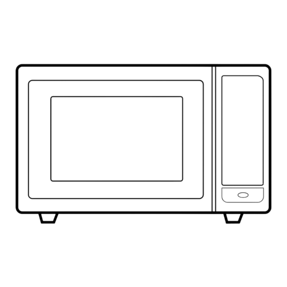
NAMES AND FUNCTION OF PARTS ¤ Door latch ƒ¡ When the door is closed it will ¤ Door release button ƒ¡Pushing this button stops oven automatically lock shut. If the door is opened while the operation and opens the door. oven is operating. -
Page 7: Control Panel
CONTROL PANEL KOR-971M0A STAGE DEFROST AUTO START WEIGHT TIME LOCK CUPS Menu Menu - Used to select foods. 1. Baked Potato Weight Weight - Used to select 2, Fish Vegetable quantity of foods. 3. Soup 4. Fish Fillets 5. Meat Loaf Muffin - used to cook muffin. - Page 8 KOR-971Q0A STAGE DEFROST AUTO START WEIGHT TIME LOCK CUPS MICROWAVE OVEN RANGE KOR-971Q Dinner plate - Used to reheat dinner plate. Dinner Frozen Beverage - Used to reheat Beverage plate Pizza beverage. Frozen pizza - Used to reheat frozen pizza. Baked Soup - Used to reheat soup.
-
Page 9: Earthing Instructions
• This appliance is supplied with cable of special type, which, if damaged, must be repaired with cable of same type. Such a cable can be purchased from DAEWOO and must be installed by a Qualified Person. 6. Examine the oven after unpacking for any damage such as: A misaligned door, Broken door, A dent in cavity. -
Page 10: Operation Procedure
OPERATION PROCEDURE This section includes useful information about oven operation. 1. Plug power supply cord into a standard 120V AC 60Hz power outlet socket. 2. After placing the food in a suitable container, open the oven door and put it on the glass tray. The glass tray must always be in place during cooking. -
Page 11: How To Set The Oven Controls
HOW TO SET THE OVEN CONTROL(KOR-971M0A) SETTING THE CLOCK SETTING THE CLOCK When the oven is first plugged in, the display will flash “ :0” and a tone will sound. If the AC power ever goes off, the display will flash “ :0” when the power comes back on. - Page 12 WEIGHT DEFROSTING WEIGHT DEFROST lets you easily defrost food by eliminating guesswork in determining defrosting time. The minimum weight for WEIGHT DEFROST is 200g. The maximum weight for WEIGHT DEFROST is 3000g. Follow the steps below for easy defrosting. DO THIS... THIS HAPPENS...
- Page 13 TIME DEFROSTING When TIME DEFROST is selected, the automatic cycle divides the defrosting time into periods of alternating defrost and stand times by cycling on and off. DO THIS... THIS HAPPENS... The WEIGHT DEFROST indicator AUTO AUTO STAGE DEFROST lights and “0” is displayed. And the “g” DEFROST START WEIGHT...
- Page 14 COOKING IN ONE STAGE DO THIS... THIS HAPPENS... The STAGE1 indicator lights and “P-” POWER is displayed. AUTO STAGE DEFROST START WEIGHT TIME 1. Touch POWER pad. LOCK CUPS The display will show what you STAGE DEFROST AUTO touched. This example shows power START WEIGHT TIME...
- Page 15 COOKING IN TWO STAGES For best results, some recipes call for one power level for a certain length of time and another power level for a different length of time. Your microwave oven can be set to change from one to another. DO THIS...
- Page 16 WEIGHT DEFROSTING AND COOKING IN TWO STAGES Some recipes require frozen foods to be thawed before cooking. This oven can be programmed to automatically defrost foods before cooking. DO THIS... THIS HAPPENS... The WEIGHT DEFROST indicator STAGE DEFROST AUTO AUTO START lights and “0”...
- Page 17 DO THIS... THIS HAPPENS... The STAGE2 indicator lights and “P-” POWER is displayed. AUTO STAGE DEFROST START WEIGHT TIME 6. Touch POWER pad. LOCK CUPS The display will show what you STAGE DEFROST AUTO touched. START WEIGHT TIME 7. Touch the number pads for the power level you want in the second stage.
- Page 18 AUTO START Allows you to program cooking to start at a time you select. The food will automatically start cooking at the desired time. Program is able up to 2 stages (not acceptable DEFROST) DO THIS... THIS HAPPENS... 1. Program the desired power level and cooking time. The AUTO START indicator lights and CLOCK/ AUTO...
- Page 19 FEEDING BOTTLE Feeding Bottle is to use to sterillize feeding bottles. DO THIS... THIS HAPPENS... When you touch Feeding Bottle pad, STAGE DEFROST AUTO FEEDING START WEIGHT TIME “2” is displayed. BOTTLE After 1.5 seconds, the display is changed into cooking time of quantity 1.
- Page 20 ONE TOUCH COOKING One touch cook allows you to cook or reheat many of your favorite foods by touching just one pad. To increase quantity, touch chosen pad until number in display is same as desired quantity to cook. (except for MUFFIN & DINNER PLATE) DO THIS...
- Page 21 DO THIS... THIS HAPPENS... When you touch DINNER PLATE pad, DINNER “300” is displayed. STAGE DEFROST AUTO PLATE After the 1.5 seconds, the display START WEIGHT TIME changed into cooking time of quantity and the oven starts cooking. 1. Touch DINNER PLATE pad. LOCK CUPS @ @ @ @ @ @ @ @ e ?
- Page 22 DO THIS... THIS HAPPENS... When you touch WEIGHT pad, WEIGHT AUTO STAGE DEFROST “1” is displayed. START WEIGHT TIME After 1.5 seconds, the display changed into cooking time of quantity and the 1. Touch WEIGHT pad. oven starts cooking. LOCK CUPS * BAKED POTATO* (156g~184g) * SOUP*...
- Page 23 HOW TO SET THE OVEN CONTROL(KOR-971Q0A) SETTING THE CLOCK SETTING THE CLOCK When the oven is first plugged in, the display will flash “ :0” and a tone will sound. If the AC power ever goes off, the display will flash “ :0” when the power comes back on. DO THIS...
- Page 24 WEIGHT DEFROSTING WEIGHT DEFROST lets you easily defrost food by eliminating guesswork in determining defrosting time. The minimum weight for WEIGHT DEFROST is 200g. The maximum weight for WEIGHT DEFROST is 3000g. Follow the steps below for easy defrosting. DO THIS... THIS HAPPENS...
- Page 25 TIME DEFROSTING When TIME DEFROST is selected, the automatic cycle divides the defrosting time into periods of alternating defrost and stand times by cycling on and off. DO THIS... THIS HAPPENS... AUTO The WEIGHT DEFROST indicator AUTO STAGE DEFROST DEFROST START lights and “0”...
- Page 26 COOKING IN ONE STAGE DO THIS... THIS HAPPENS... The STAGE1 indicator lights and “P-” POWER is displayed. AUTO STAGE DEFROST START WEIGHT TIME 1. Touch POWER pad. LOCK CUPS The display will show what you STAGE DEFROST AUTO touched. This example shows power START WEIGHT TIME...
- Page 27 COOKING IN TWO STAGES For best results, some recipes call for one power level for a certain length of time and another power level for a different length of time. Your microwave oven can be set to change from one to another. DO THIS...
- Page 28 WEIGHT DEFROSTING AND COOKING IN TWO STAGES Some recipes require frozen foods to be thawed before cooking. This oven can be programmed to automatically defrost foods before cooking. DO THIS... THIS HAPPENS... The WEIGHT DEFROST indicator STAGE DEFROST AUTO AUTO START WEIGHT TIME...
- Page 29 DO THIS... THIS HAPPENS... The STAGE2 indicator lights and “P-” POWER is displayed. AUTO STAGE DEFROST START WEIGHT TIME 6. Touch POWER pad. LOCK CUPS The display will show what you AUTO STAGE DEFROST touched. START WEIGHT TIME 7. Touch the number pads for the power level you want in the second stage.
- Page 30 AUTO START Allows you to program cooking to start at a time you select. The food will automatically start cooking at the desired time. Program is able up to 2 stages (not acceptable DEFROST) DO THIS... THIS HAPPENS... 1. Program the desired power level and cooking time. The AUTO START indicator lights and CLOCK/ AUTO...
- Page 31 FEEDING BOTTLE Feeding Bottle is to use to sterillize feeding bottles. DO THIS... THIS HAPPENS... When you touch Feeding Bottle pad, AUTO FEEDING STAGE DEFROST START WEIGHT TIME “2” is displayed. BOTTLE After 1.5 seconds, the display is changed into cooking time of quantity 1.
- Page 32 ONE TOUCH COOKING One touch cook allows you to cook or reheat many of your favorite foods by touching just one pad. To increase quantity, touch chosen pad until number in display is same as desired quantity to cook. (except for MUFFIN & DINNER PLATE) DO THIS...
- Page 33 * BEVERAGE* (250ml/cup) ¡ 1 cup (mug) : Touch BEVERAGE once. ¡ 2 cups (mugs) : Touch BEVERAGE twice within 1.5 seconds. ¡ 3 cups (mugs) : Touch BEVERAGE three tmes within1.5 seconds. @ @ @ @ @ @ @ @ e ? @ @ @ @ @ @ @ @ e ? @ @ @ @ @ @ @ @ ? e @ @ @ @ @ @ @ @ e ? @ @ @ @ @ @ @ @ ? e @ @ @ @ @ @ @ @ e ? @ @ @ @ @ @ @ @ ? e @ @ @ @ @ @ @ @ e ? @ @ @ @ @ @ @ @ ? e @ @ @ @ @ @ @ @ e ? @ @ @ @ @ @ @ @ ? e @ @ @ @ @ @ @ @ e ? @ @ @ @ @ @ @ @ ? e @ @ @ @ @ @ @ @ e ? @ @ @ @ @ @ @ @ ? e @ @ @ @ @ @ @ @ e ? @ @ @ @ @ @ @ @ ? e @ @ @ @ @ @ @ @ e ? @ @ @ @ @ @ @ @ ? e @ @ @ @ @ @ @ @ e ? @ @ @ @ @ @ @ @ ? e @ @ @ @ @ @ @ @ e ? @ @ @ @ @ @ @ @ ? e @ @ @ @ @ @ @ @ e ? @ @ @ @ @ @ @ @ ? e @ @ @ @ @ @ @ @ e ? @ @ @ @ @ @ @ @ ? e @ @ @ @ @ @ @ @ e ? @ @ @ @ @ @ @ @ ? e @ @ @ @ @ @ @ @ e ? @ @ @ @ @ @ @ @ ? e @ @ @ @ @ @ @ @ e ? @ @ @ @ @ @ @ @ ? e @ @ @ @ @ @ @ @ e ? @ @ @ @ @ @ @ @ ? e @ @ @ @ @ @ @ @ e ? @ @ @ @ @ @ @ @ ? e @ @ @ @ @ @ @ @ e ? @ @ @ @ @ @ @ @ ? e @ @ @ @ @ @ @ @ e ? @ @ @ @ @ @ @ @ ? e @ @ @ @ @ @ @ @ e ? @ @ @ @ @ @ @ @ ? e @ @ @ @ @ @ @ @ e ? @ @ @ @ @ @ @ @ e ? @ @ @ @ @ @ @ @ ? e @ @ @ @ @ @ @ @ e ? @ @ @ @ @ @ @ @ ? e @ @ @ @ @ @ @ @ e ? @ @ @ @ @ @ @ @ ? e @ @ @ @ @ @ @ @ e ? @ @ @ @ @ @ @ @ ? e @ @ @ @ @ @ @ @ e ? @ @ @ @ @ @ @ @ ? e @ @ @ @ @ @ @ @ e ? @ @ @ @ @ @ @ @ ? e @ @ @ @ @ @ @ @ e ? @ @ @ @ @ @ @ @ ? e @ @ @ @ @ @ @ @ e ? @ @ @ @ @ @ @ @ ? e @ @ @ @ @ @ @ @ e ? @ @ @ @ @ @ @ @ ? e @ @ @ @ @ @ @ @ e ? @ @ @ @ @ @ @ @ ? e @ @ @ @ @ @ @ @ e ? @ @ @ @ @ @ @ @ ? e @ @ @ @ @ @ @ @ e ? @ @ @ @ @ @ @ @ ? e @ @ @ @ @ @ @ @ e ? @ @ @ @ @ @ @ @ ? e @ @ @ @ @ @ @ @ e ? @ @ @ @ @ @ @ @ ? e @ @ @ @ @ @ @ @ e ? @ @ @ @ @ @ @ @ ? e @ @ @ @ @ @ @ @ e ? @ @ @ @ @ @ @ @ ? e @ @ @ @ @ @ @ @ e ? @ @ @ @ @ @ @ @ ? e @ @ @ @ @ @ @ @ e ? @ @ @ @ @ @ @ @ ? e @ @ @ @ @ @ @ @ e ? @ @ @ @ @ @ @ @ ? e @ @ @ @ @ @ @ @ e ? @ @ @ @ @ @ @ @ ? e @ @ @ @ @ @ @ @ e ? @ @ @ @ @ @ @ @ ? e @ @ @ @ @ @ @ @ e ? @ @ @ @ @ @ @ @ @ @ @ @ @ @ @ @ e ?
- Page 34 * SOUP* ¡ 250g : Touch SOUP once. ¡ 350g : Touch SOUP twice within1.5 seconds. @ @ @ @ @ @ @ @ e ? @ @ @ @ @ @ @ @ e ? @ @ @ @ @ @ @ @ ? e @ @ @ @ @ @ @ @ e ? @ @ @ @ @ @ @ @ ? e @ @ @ @ @ @ @ @ e ? @ @ @ @ @ @ @ @ ? e @ @ @ @ @ @ @ @ e ? @ @ @ @ @ @ @ @ ? e @ @ @ @ @ @ @ @ e ? @ @ @ @ @ @ @ @ ? e @ @ @ @ @ @ @ @ e ? @ @ @ @ @ @ @ @ ? e @ @ @ @ @ @ @ @ e ? @ @ @ @ @ @ @ @ ? e @ @ @ @ @ @ @ @ e ? @ @ @ @ @ @ @ @ ? e @ @ @ @ @ @ @ @ e ? @ @ @ @ @ @ @ @ ? e @ @ @ @ @ @ @ @ e ? @ @ @ @ @ @ @ @ ? e @ @ @ @ @ @ @ @ e ? @ @ @ @ @ @ @ @ ? e @ @ @ @ @ @ @ @ e ? @ @ @ @ @ @ @ @ ? e @ @ @ @ @ @ @ @ e ? @ @ @ @ @ @ @ @ ? e @ @ @ @ @ @ @ @ e ? @ @ @ @ @ @ @ @ ? e @ @ @ @ @ @ @ @ e ? @ @ @ @ @ @ @ @ ? e @ @ @ @ @ @ @ @ e ? @ @ @ @ @ @ @ @ ? e @ @ @ @ @ @ @ @ e ? @ @ @ @ @ @ @ @ ? e @ @ @ @ @ @ @ @ e ? @ @ @ @ @ @ @ @ ? e @ @ @ @ @ @ @ @ e ? @ @ @ @ @ @ @ @ ? e @ @ @ @ @ @ @ @ e ? @ @ @ @ @ @ @ @ ? e @ @ @ @ @ @ @ @ e ? @ @ @ @ @ @ @ @ ? e @ @ @ @ @ @ @ @ e ? @ @ @ @ @ @ @ @ e ? @ @ @ @ @ @ @ @ ? e @ @ @ @ @ @ @ @ e ? @ @ @ @ @ @ @ @ ? e @ @ @ @ @ @ @ @ e ? @ @ @ @ @ @ @ @ ? e @ @ @ @ @ @ @ @ e ? @ @ @ @ @ @ @ @ ? e @ @ @ @ @ @ @ @ e ? @ @ @ @ @ @ @ @ ? e @ @ @ @ @ @ @ @ e ? @ @ @ @ @ @ @ @ ? e @ @ @ @ @ @ @ @ e ? @ @ @ @ @ @ @ @ ? e @ @ @ @ @ @ @ @ e ? @ @ @ @ @ @ @ @ ? e @ @ @ @ @ @ @ @ e ? @ @ @ @ @ @ @ @ ? e @ @ @ @ @ @ @ @ e ? @ @ @ @ @ @ @ @ ? e @ @ @ @ @ @ @ @ e ? @ @ @ @ @ @ @ @ ? e @ @ @ @ @ @ @ @ e ? @ @ @ @ @ @ @ @ ? e @ @ @ @ @ @ @ @ e ? @ @ @ @ @ @ @ @ ? e @ @ @ @ @ @ @ @ e ? @ @ @ @ @ @ @ @ ? e @ @ @ @ @ @ @ @ e ? @ @ @ @ @ @ @ @ ? e @ @ @ @ @ @ @ @ e ? @ @ @ @ @ @ @ @ ? e @ @ @ @ @ @ @ @ e ? @ @ @ @ @ @ @ @ ? e @ @ @ @ @ @ @ @ e ? @ @ @ @ @ @ @ @ ? e @ @ @ @ @ @ @ @ e ? @ @ @ @ @ @ @ @ ? e @ @ @ @ @ @ @ @ e ? @ @ @ @ @ @ @ @ ? e @ @ @ @ @ @ @ @ e ? @ @ @ @ @ @ @ @ ? e @ @ @ @ @ @ @ @ e ? @ @ @ @ @ @ @ @ @ @ @ @ @ @ @ @ e ? @ @ @ @ @ @ @ @...
- Page 35 MORE, LESS MORE pad : adds for 10 seconds to 20 seconds. LESS pad : remove for 10 seconds to 20 seconds. These pad only work one touch cooking and feeding bottle mode. And always input previously CHILD SAFETY LOCK The safety lock prevents unwanted oven operation such as by small children.
-
Page 36: Interlock Mechanism Functions And Adjustments
INTERLOCK MECHANISM FUNCTIONS AND ADJUSTMENTS The door lock mechanism is a device which has been specially designed to completely eliminate microwave radiation when the door is opened during operation, and thus to perfectly prevent the danger resulting from the leakage of microwave. (1) Primary interlock switch When the door is closed, the hook locks the oven door. - Page 37 (2) Monitor interlock switch When the door is closed, the hook pushes the lever forward, and pushes the Latch Lever downward the lever press the button of the interlock monitor switch to bring it under ‘OFF’ condition. The latch Lever press the button on the secondary interlock switch to bring it under ‘ON’...
-
Page 38: Precautions For Disassembly And Repair
PRECAUTIONS FOR DISASSEMBLY AND REPAIR - Cautions to be observed when trouble shooting. Unlike many other appliances, the microwave oven is high-voltage, high-current equipment. It is completely safe during normal operation. However, carelessness in servicing the oven can result in an electric shock or possible danger from a short circuit. -
Page 39: Disassembly And Assembly
DISASSEMBLY AND ASSEMBLY 1. To remove cabinet. (Refer to Fig. 1) 1) Remove four screws on cabinet back. 2) Push the cabinet backward. Fig. 1 2. To remove guide wind assembly. (Refer to Fig. 2) 1) Remove the screw ¤ , guide wind ¤Œ . 2) Pull the fan ¤Øto the motor shaft. - Page 40 3. To remove H.V. transformer. (Refer to Fig. 3) 1) Remove four screws ¤ which secure the H.V. Transformer bracket to the base plate. 2) Remove the H.V. Transformer ¤Ł . Fig. 3 High voltage circuit wiring H.V. Capacitor H.V. Diode Magnetron H.V.
- Page 41 4. To remove magnetron. (Refer to Fig. 4) 1) Remove three screws ¤Ł which secure the magnetron ¤ . 2) Remove the magnetron. 3) Reverse the above steps for reassembly. Fig. 4 @ @ @ @ @ @ @ @ e ? @ @ @ @ @ @ @ @ e ? @ @ @ @ @ @ @ @ ? e @ @ @ @ @ @ @ @ e ? @ @ @ @ @ @ @ @ ? e @ @ @ @ @ @ @ @ e ? @ @ @ @ @ @ @ @ ? e @ @ @ @ @ @ @ @ e ? @ @ @ @ @ @ @ @ ? e @ @ @ @ @ @ @ @ e ? @ @ @ @ @ @ @ @ ? e @ @ @ @ @ @ @ @ e ? @ @ @ @ @ @ @ @ ? e @ @ @ @ @ @ @ @ e ? @ @ @ @ @ @ @ @ ? e @ @ @ @ @ @ @ @ e ? @ @ @ @ @ @ @ @ ? e @ @ @ @ @ @ @ @ e ? @ @ @ @ @ @ @ @ ? e @ @ @ @ @ @ @ @ e ? @ @ @ @ @ @ @ @ ? e @ @ @ @ @ @ @ @ e ? @ @ @ @ @ @ @ @ ? e @ @ @ @ @ @ @ @ e ? @ @ @ @ @ @ @ @ ? e @ @ @ @ @ @ @ @ e ? @ @ @ @ @ @ @ @ ? e @ @ @ @ @ @ @ @ e ? @ @ @ @ @ @ @ @ ? e @ @ @ @ @ @ @ @ e ? @ @ @ @ @ @ @ @ ? e @ @ @ @ @ @ @ @ e ? @ @ @ @ @ @ @ @ ? e @ @ @ @ @ @ @ @ e ? @ @ @ @ @ @ @ @ ? e @ @ @ @ @ @ @ @ e ? @ @ @ @ @ @ @ @ ? e @ @ @ @ @ @ @ @ e ? @ @ @ @ @ @ @ @ ? e @ @ @ @ @ @ @ @ e ? @ @ @ @ @ @ @ @ ? e @ @ @ @ @ @ @ @ e ? @ @ @ @ @ @ @ @ ? e @ @ @ @ @ @ @ @ e ? @ @ @ @ @ @ @ @ @ @ @ @ @ @ @ @ e ?
- Page 42 PART NAME DESCRIPTION Q’TY REMARK 3516715100 CONTROL-PANEL 441G430171 SPRING BUTTON SWP DIA. 0.7 3516905010 BUTTON DOOR OPEN 3518520500 KOR-971M0S SWITCH MEMBRANE 3518520510 KOR-971Q0S PKMPMSMX00 PCB MAIN MANUAL AS KOR-971M0A 7122401211 SCREW TAPPING T2S TRS 4X12 MFZN 3513702300 LEVER DOOR OPEN...
- Page 43 6. To remove door assembly. (Refer to Fig. 7) 1) Remove two screws which secure to hinge. 2) Remove door assembly ¤Ł . 3) Remove door above for reassembly taking case to replace fixing glue. 7. To remove door part. (Refer to Fig. 8) (1) Remove the frame door ¤...
- Page 44 8. Method to reduce the gap between the door seal and the oven front surface. (1) To reduce gap located on part ‘A’. 1) Remove the cabinet. 2) Loosen a screw on top door hinge, then push the door to contact the door seal to oven front surface.
- Page 45 9. To remove tray motor and under Heater. (Refer to Fig. 9) 1) Cut the tray motor cover parts from the base plate (Refer to Fig. 9). 2) Remove two screws ¤Łwhich secure the tray motor ¤ . CUTTING(8EA) Fig. 9...
-
Page 46: Trouble Shooting Guide
TROUBLE SHOOTING GUIDE Following the procedures below to check if the oven is defective or not. 1. Check grounding before checking trouble. 2. Be careful of the high voltage circuit. 3. Discharge the high voltage capacitor. 4. When checking the continuity of switches or of the high voltage transformer, disconnect one lead wire from these parts and then check continuity with the AC plug removed. - Page 47 (TROUBLE 2) Digital readout display does not show programming, even if the membrane keyboard is programmed by touching proper pads. Condition Check Result Cause Remedy Normal Display does not Check each pad for Malfunction of Replace show programming at all, continuity of the touch control control box...
- Page 48 2. Type of encoding and pad names. (KOR-971M) DINNER POWER PLATE FROZEN SPEEDY BEVERAGE MUFFIN PIZZA COOK FEEDING START LESS MORE BOTTLE STOP/ CLOCK/ AUTO WEIGHT MENU CLEAR A.START DEFROST Fig. 11 Key Matrix The membrane keyboard consists of 25 keys whose configurations are described above and provide 11 pad terminations to be connected to the touch control circuit as Fig.
- Page 49 (KOR-971Q) BAKED DINNER FRESH SOUP POWER POTATO PLATE VEGETABLE FROZEN SPEEDY BEVERAGE MUFFIN PIZZA COOK FEEDING START LESS MORE BOTTLE STOP/ CLOCK/ AUTO CLEAR A.START DEFROST Fig. 11 Key Matrix The membrane keyboard consists of 26 keys whose configurations are described above and provide 11 pad terminations to be connected to the touch control circuit as Fig.
- Page 50 (TROUBLE 3) Oven does not operate at all; Display window does not display any figures and any inputs can not be accepted. Condition Check Result Casue Remedy 20A fuse Check continuity Continuity Malfunction of Replace Primary blows Interlock Monitor Interlock monitor Interlock Switch switch with door switch...
- Page 51 Condition Check Result Cause Remedy Outlet has Check continuity of Defective mangetron Replace proper voltage. magnetron thermostat Continuity thermostat. Fuse does not open. Check continuity of Open power supply Replace power supply cord. Continuity cord. Defective P.W.B. Normal Replace ASSY Display do not shown Malfunction of D.O.M Replace...
- Page 52 (TROUBLE 5) No microwave oscillation even though fan motor rotates. Condition Check Result Cause Remedy No microwave Check continuity of Defective magnetron Replace oscillation connecting wire of Continuity magnetron Continuity Check continuity of Defective high voltage Replace filament terminal of Continuity transformer, high voltage...
- Page 53 (TROUBLE 6) Microwave Output power is low. First of all, check if output power is really low following “measurement of the microwave output power”. Condition Check Result Cause Remedy Output power Check the power Lower than Decrease in Customer education is low.
-
Page 54: Measurement
MEASUREMENT @ @ @ @ @ @ @ @ e ? @ @ @ @ @ @ @ @ e ? @ @ @ @ @ @ @ @ ? e @ @ @ @ @ @ @ @ e ? @ @ @ @ @ @ @ @ ? e @ @ @ @ @ @ @ @ e ? @ @ @ @ @ @ @ @ ? e @ @ @ @ @ @ @ @ e ? @ @ @ @ @ @ @ @ ? e @ @ @ @ @ @ @ @ e ? @ @ @ @ @ @ @ @ ? e @ @ @ @ @ @ @ @ e ? @ @ @ @ @ @ @ @ ? e @ @ @ @ @ @ @ @ e ? @ @ @ @ @ @ @ @ ? e @ @ @ @ @ @ @ @ e ? @ @ @ @ @ @ @ @ ? e @ @ @ @ @ @ @ @ e ? @ @ @ @ @ @ @ @ ? e @ @ @ @ @ @ @ @ e ? @ @ @ @ @ @ @ @ ? e @ @ @ @ @ @ @ @ e ? @ @ @ @ @ @ @ @ ? e @ @ @ @ @ @ @ @ e ? @ @ @ @ @ @ @ @ ? e @ @ @ @ @ @ @ @ e ? @ @ @ @ @ @ @ @ ? e @ @ @ @ @ @ @ @ e ? @ @ @ @ @ @ @ @ ? e @ @ @ @ @ @ @ @ e ? @ @ @ @ @ @ @ @ ? e @ @ @ @ @ @ @ @ e ? @ @ @ @ @ @ @ @ ? e @ @ @ @ @ @ @ @ e ? @ @ @ @ @ @ @ @ ? e @ @ @ @ @ @ @ @ e ? @ @ @ @ @ @ @ @ ? e @ @ @ @ @ @ @ @ e ? @ @ @ @ @ @ @ @ ? e @ @ @ @ @ @ @ @ e ? @ @ @ @ @ @ @ @ ? e @ @ @ @ @ @ @ @ @ @ @ @ @ @ @ @ e ? @ @ @ @ @ @ @ @... - Page 55 2-2. Judgement The value of resistance should be applied to the value specified below. Door Open Closed Primary Interlock Switch Secondary Interlock Switch Interlock Monitor Circuit 3. Microwave Leakage Test 3-1. Warning 1) DO NOT place your hands into any suspected microwave leakage field unless the safe density level is known.
-
Page 56: Component Test Procedure
COMPONENT TEST PROCEDURE 1. High voltage is present at the high voltage terminal of the high voltage transformer during any cook cycle. 2. It is neither necessary nor advisable to attempt measurement of the high voltage. 3. Before touching any oven components or wiring, always unplug the oven from its power source and discharge the capacitor (see page 36). -
Page 57: Wiring Diagram
WIRING DIAGRAM... -
Page 58: Exploded Views And Parts List
EXPLODED VIEWS AND PARTS LIST... - Page 59 PART NAME DESCRIPTION PART CODE Q’TY CAVITY WELD AS KOR-971M0S 3516107940 DOOR AS KOR-971M0S 3511708360 KOR-971M0A PKCPSWMX00 CONTROL-PANEL AS KOR-971Q0A PKCPSWM600 COVER WAVE GUIDE MICA T0.5 3511403800 SCREW TAPPING T1 BIN 4X8 MFNI 7113400814 COUPLER 3517400600 MOTOR SYNCRO 220V 2.5W GM-16-24FD12...
-
Page 60: Printed Circuit Board
PRINTED CIRCUIT BOARD 1. CIRCUIT CHECK PROCEDURE 1) Low Voltage Transformer (DMR-604P) Check. The low voltage transformer is located on the P.C.B. Measuring condition : Input voltage ; 120V Measuring condition : Frequency ; 60Hz Voltage LOAD NO LOAD Terminal 6 - 17 8 - 10 2.4V... - Page 61 3) Display problems CAUSE MEASUREMENT RESULT REMEDY Poor contact between Check the voltage Fix the PIN 1 & 25 2.4 VAC P.C.B. and display filament. of PIN 1 & PIN 25. on the P.C.B. Defective Display Refer to “The display Replace P.C.B.
- Page 62 CHECK METHOD POINT STAGE RELAY “2” ON -24VDC RELAY “2” OFF (2) When touching “START” pad, oven lamp turns on. Fan motor and turntable rotate and cook indicator in display comes on. * Cause : RELAY “1” does not operate. -24V CHECK METHOD POINT...
- Page 63 6) When the digital clock does not operate properly. POINT WAVEFORM T ; 16.67 ms T ; 16.67ms -14V If clock does not keep exact time, you must check resistor R11, R17.
-
Page 64: P.c.b Circuit Diagram
P.C.B CIRCUIT DIAGRAM KOR-971M0A... - Page 65 KOR-971Q0A...
- Page 66 COMPONENT INFORMATION 1) Transistor Q 1, 3-5 Emitter Collector Base 2) Diode and Zener Diode DIODE CATHODE (K) ANODE (A) D1-7, 9-14 ZENER CATHODE (K) ANODE (A) ZD 1-3 DIODE...
- Page 67 4. PRINTED CIRCUITS BOARD MP-1 MP-2 MP-3...
- Page 68 5. P.C.B LOCATION NO. NAME SYMBOL SPECIFICATION PART CODE Q¡ ¡ fl fl TY RESISTOR R10, 12, 13, 18 4.7kΩ, 1/6W, RD-AZ472J- RESISTOR 200Ω, 1/6W, RD-AZ201J- RESISTOR R5, 8 20kΩ, 1/6W, RD-AZ203J- RESISTOR 1MΩ, 1/6W, RD-AZ105J- RESISTOR R2, 4, 6, 9, 15, 20 1kΩ, 1/6W, RD-AZ102J-...
Need help?
Do you have a question about the KOR-971M0A and is the answer not in the manual?
Questions and answers